Page is loading ...

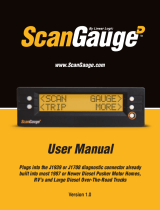
User Manual
Plugs into the diagnostic connector already
built into all 1996 or newer cars and light trucks.
www.ScanGauge.com
Version 1.0

WARNING
Use of the ScanGauge while driving could lead to an accident and serious injuries.
The primary attention of the driver should always be on safe driving. As with any
gauge or other instrumentation system in a motor vehicle, the information should
be observed as part of a normal sequence of observations performed in the
operation of the vehicle. Changes to the selections in the ScanGauge should
only be made when it is safe to do so. The driver must remain attentive to driving
the vehicle.
The mounting of the ScanGauge and the routing of the cable connecting it to
the vehicle should be done with suitable caution so it does not create an unsafe
condition. This includes but is not limited to the following restrictions:
• Do Not mount the ScanGauge where it can obstruct the
view of the driver.
• Do Not mount the ScanGauge in a manner that could cause
it to be propelled through the vehicle during an accident
causing injury, such as over or near an air bag.
• Do Not route the cable in a manner that would interfere
with the operation of the vehicle controls.
RIGHTS AND OBLIGATIONS
The ScanGauge may be used on any number of vehicles. The software
contained in the ScanGauge is copyright protected by Linear Logic and may not
be transferred or disassembled and used in another product, in part or in whole.
The artwork used in generation of the circuitry is also copyright protected and
cannot be used in part or in whole by any person or entity without the express
written permission of Linear Logic.
© 2004-2011 by Linear Logic. All rights reserved.
2 — www.ScanGauge.com

Table of Contents
Version 1.0
Information in this manual and the specifications and operation of
the ScanGauge itself are subject to change without notice.
Installing the ScanGauge 4
ScanGauge Overview 5
Basic Operation and Features 6
Installation 8
Setup and Calibration 11
Initial Setup 12
Advanced Setup Options 15
Backlight Display 20
Calibration 22
Operating Your ScanGauge 24
Digital Gauges 25
Trip Computers 30
Scan Tool 36
Troubleshooting 39
Where to Get Support 40
Reset Your ScanGauge 42
View Firmware Version of Your ScanGauge 42
Read or Set the Operating Mode 43
Warranty Information 44
3

Installing the ScanGauge
The ScanGauge is simple to install and requires no additional power
source other than the OBDII connector.
There are, however, some important considerations when choosing a
location for your ScanGauge. Please see the Installation section for
detailed information.
ScanGauge Overview 5
Locating the OBDII Connector 8
Mounting Your ScanGauge 8
Connecting Your ScanGauge 9
Important Installation Considerations 9
4 — www.ScanGauge.com

Overview
Package Contents
• ScanGauge
• 6ft OBDII Cable
• Velcro
®
Strip
• User Manual
• Quick Start Guide
ScanGauge Overview
A. Function/Selection Button
The function buttons are used to make
selections and to navigate the menu
system of the ScanGauge
B. Function/Selection Button
C. Function/Selection Button
D. Function/Selection Button
E. HOME Button Use the HOME Button to quickly get
back to the home screen
F. LCD Display Screen Displays the information the
ScanGauge records
G. OBDII Connection Plug Connects the ScanGauge to the vehicle
Front
Back
A
B
C
D
E
G
F
5

Basic Operation and Features
Menu and Selection Buttons
The ScanGauge interface is made up of 5
buttons; one HOME and 4 function/select
buttons. The HOME button, located in the lower
right corner of the front face and marked with a
green circle, has a single function — to display
the Home Screen. Pushing the HOME button
will always display the Home Screen as shown
to the right.
The function/select buttons are located at each corner
of the display. The function of these buttons will vary
depending on the particular screen you are currently
viewing.
In general, when a “<” or “>” is displayed next to the
button, pressing the button will move you to the next
or previous selection for the currently selected feature.
Use the diagram to the left for an explanation of
possible button functions.
From the Home Screen, pressing the button at the
upper left corner will bring up selections for scanning
the vehicle’s computer for Trouble Codes and other
information. Pressing the upper right button will bring
up gauges showing the current information for the
vehicle, such as speed, RPM, fuel economy, etc. Pressing the lower left button shows trip information
and the lower right button brings up more types of selections.
Automatic Sleep Mode
About 12 seconds after turning off the vehicle or pressing a button after the vehicle engine is turned
off, the ScanGauge will automatically power down into a sleep mode. Starting the engine or pressing
the HOME button will automatically reactivate the ScanGauge, and it will return to the screen and lamp
settings it had just before it went to sleep.
If you need to disconnect the ScanGauge, wait until it has gone to sleep before you do it.
This will allow all settings and trip information to be saved in Flash memory and restored
when it is reconnected.
TRIP
SCAN GAUGE
MORE
Push the HOME button to return to the HOME menu at anytime.
Button Symbols
Symbol Function/Action
>
Move to next selection
<
Move to previous selection
Move up one level
Step into function
(not shown in above example)
<
DISTANCE
75.2Mi
>
6 — www.ScanGauge.com

Overview
Automatic Mode Recognition
Different vehicles use different types of signaling from their computers. In most cases, the ScanGauge
can quickly determine which type your vehicle is using. You don’t have to know which type it is for it to
be used.
Automatic Repeat Buttons
Pressing the buttons and holding them for more than a second will cause them to automatically repeat
at a rate of about 2 times per second. This allows for rapid stepping to a value without a lot of button
pressing.
Real-time Feedback Graph
The ScanGauge provides you with real-time information about your vehicle’s fuel economy through an
intuitive real-time graphic display.
Flash Memory
The ScanGauge uses a type of memory that doesn’t require batteries or a source of power to main-
tain. This means that your settings will not be lost if you disconnect the vehicle battery or disconnect
the ScanGauge.
Customizable Backlight Color
Choose from 7 standard backlight colors or program your own for 63 possible colors. The backlight
intensity is also adjustable and can be set to Off, Low and High intensities.
7

1. Locate the OBDII connector.
This connector is normally located under the dash on either side
of the steering column. It can also be located under the dash
on the passenger side in some vehicles. On rare occasions it is
behind the ashtray in the dash or in the armrest. It may have a
cover on it that can be pulled off by hand.
2. Locate a place for the ScanGauge.
You can use the sticky-back Velcro® supplied with the
ScanGauge to attach it to the location you have chosen. The
Velcro
®
attachment allows you to easily remove it and use it to
troubleshoot another vehicle and then return it to this vehicle.
The location should be where it can easily be seen from the
normal driving position. It should not be placed where it will
obstruct the driver’s view outside the vehicle or of other gauges.
DO NOT mount the ScanGauge over an air bag
cover where it could be propelled by a deploying
air bag.
3. Route the cable.
Route the cable from the OBDII connector and plug the small
end of the cable into the back or side of the ScanGauge.
IMPORTANT: A pin in the cable is connected to
the vehicle’s 12V system. Do not short any pins of
the small connector to metal or other ground
when the OBDII plug is plugged into the OBDII
connector.
4. Turn the vehicle on.
If the vehicle can be run, start it. If it cannot be run, turn the key
to the Run position. This is the position it is normally in when the
vehicle is being driven.
Large end of the cable
connects to your vehicle.
Small end of the cable
connects to your ScanGauge.
Installation
Typical OBDII
connector location
OBDII Connector
8 — www.ScanGauge.com

Overview
5. Plug the ScanGauge plug into the OBDII socket.
The ScanGauge derives all the power it needs from the OBDII connector. No other connections
are needed for its operation.
Wait for the ScanGauge to connect. When the ScanGauge is first connected, it attempts to
communicate with the vehicle. Communications can be established with the key in the Run
position, even if the engine is not actually running. It could take up to 60 seconds for the
connection to be made after the unit is plugged in with the key in the Run position.
While establishing communications, the screen will display:
TRIP
Connecting
MORE
Connecting Screen
TRIP
SCAN GAUGE
MORE
HOME Screen
Up to 60
seconds
If it does not stop saying “Connecting” or the screen goes blank after 60 seconds,
refer to Troubleshooting on page 40.
The TRIP and MORE buttons can be used even if a connection is not established. If
communication with the vehicle ECU is not completed within about 75 seconds, the ScanGauge
goes to sleep. It will continue to attempt to connect when the vehicle is restarted or the HOME
button pressed. When communication has been established, the display will change over to that
which was displayed the last time it went to sleep or to the HOME screen.
6. If this is the first time it has been used on this vehicle, follow the
procedures outlined in Setting Up Your ScanGauge on page 12.
Important Installation Considerations
TheScanGaugehasanoperatingtemperaturerangeof0˚Fto160˚F(-18˚Cto71˚C).Athighertem-
peratures, the display will become dark and difficult to read. At lower temperatures, the contrast will be
reducedandthecharacterswillchangemoreslowly.Aslongasthetemperaturedoesn’texceed–22˚F
to176˚F(-30˚Cto80˚C),thedisplaywillreturntonormaloperationwhentheScanGaugetemperature
returns to the normal operating temperature range.
• A location in direct sunlight on the dashboard in a closed vehicle could exceed the normal
operating temperature. The use of windshield shades or covering the ScanGauge with a
9

piece of paper can significantly reduce this temperature. If attached with Velcro®, you can
also move it temporarily to a location away from the sun.
• DO NOT mount the ScanGauge over an air bag cover where it could be propelled by a
deploying air bag.
• A pin (pin 16) in the cable is connected to the vehicle 12V system. DO NOT short any pins
of the small connector to metal or other ground when the OBDII plug is plugged into the
OBDII connector.
• The location should be where it can easily be seen from the normal driving position. It
should not be placed where it will obstruct the driver’s view outside the vehicle or of
other gauges.
10 — www.ScanGauge.com

Set Up and Calibrate Your ScanGauge
Set Up and Calibrate
Your ScanGauge
To get the most out of your ScanGauge, it is important to follow the setup
and calibration procedures to ensure your ScanGauge reports accurate
information.
This section outlines the various setup options and provides detail infor-
mation about calibrating the ScanGauge for the most accurate readings.
Setting Up Your ScanGauge
Initial Setup Overview 12
Advanced Setup Overview 15
Backlight Display Options 20
Calibration
Calibration Overview 22
First Fill-up Procedure 22
Helpful Hints 23
Second Fill-up Procedure 23
11

Initial Setup Overview
To properly use your ScanGauge, you must first set up the vehicle parameters. Basic setup param-
eters include engine size, fuel tank size, fuel type and unit of measure. Advanced parameters are also
available and are covered later in this chapter.
Access the Setup Options
To access the setup screens, press the function
button next to MORE on the Home Screen. Next
press the function button next to SETUP.
Setting Up Your ScanGauge
See page 15 for Advanced Setup Options
< >FUEL
< >
G
< >TEMP.
< >
°F
< >PRESS.
< >
PSI
< >ENGINE
< >
3.0 L
< >TANK
< >
15 G
< >TYPE
< >
GAS
< >CURRENCY
< >
$
< >CO2 UNIT
< >
KG
< >ADV SET
< FILLUP >
< SETUP >
TRIP
SCAN GAUGE
MORE
Use the lower buttons to adjust the
currently selected setup parameter
Use the upper buttons to move to the next or
previous setup parameter
Displays the currently selected setup parameter
<DISTANCE>
< >
MILES
Loop
Loop
12 — www.ScanGauge.com

Set Up and Calibrate Your ScanGauge
Basic Setup Parameters
Setup Parameter Display Options Description
Distance Units DISTANCE Miles
Kilometers
The Setup Parameteres include multiple
units of measure settings, including
Distance, Fuel, Temperature and Pressure.
Each is set independently of the other and
can be used in any combination.
Making changes to these settings causes
your ScanGauge to use these units when
reporting and measuring data.
Fuel Units FUEL Gallons
Liters
Temperature Units TEMP. Fahrenheit(˚F)
Celsius(˚C)
Pressure Units PRESS. PSI
KPA
Engine Size ENGINE 0.0 - 9.9 (Liters) Increase or decrease the Liters size until it
matches the size of your engine.
Tank Size TANK 0 - 255
Gallons/liters
Is adjustable in 1-gallon or liter increments
depending on how you set the FUEL
UNITS parameter.
Fuel Type TYPE GAS
DIESELa
DIESELb
HYBRID
LPG
Most diesel vehicles use the DIESELa
setting. See special notes on page 14.
Hybrid vehicles must choose HYBRID or
the ScanGauge will go to sleep when the
engine automatically shuts off.
Set to LPG for propane powered vehicles.
Currency Type CURRENCY
$, £, ¥, €
Choose the currency symbol ScanGauge
should use to display monitor values.
CO2
Units CO2 KG
LBS
Set the unit of measure ScanGauge should
use when tracking CO2.
Tips for Setting the Tank Size
The size will use Gallons or Liters depending on the selection you made in the Fuel Units Screen
(FUEL). If the size in the manual is not in whole units, use the next lower value. For instance, if the
capacity is 17.5 gallons, use 17 gallons.
It is dangerous to run a vehicle out of fuel and can damage the fuel pump. Do not rely on
the fuel gauge or ScanGauge at low fuel levels or low remaining distance or time.
13

Can the ScanGauge Use Imperial Gallons?
ScanGauge uses gallons as a unit label, not a unit of measurement. Because of this, it can read in either
US or Imperial Gallons without conversion. Make sure all units entered into ScanGauge are consistent,
and the readings should remain accurate for US or Imperial Gallons.
Can ScanGauge Display Liters per Hundred Kilometer?
By default, ScanGauge will express fuel economy in Liters per Hundred Kilometers (LHK), provided you
have set fuel to LITERS and distance to KILOMETERS. For more information see LHK under Advanced
Setup on page 15.
Diesel Vehicles: Determining the Diesel Type
If your vehicle uses diesel fuel and you’re not sure which setting to use in the FUEL TYPE parameter,
you can determine the type by performing the following procedure:
•Set the Engine Size (ENGINE) to match the liter size of your vehicle’s engine.
•Set Fuel Type (TYPE) to DIESELa.
•Run the engine until warmed up to operating temperature.
•Park the vehicle and set it in Park or Neutral.
•While the engine is idling, select GAUGE from the Home Screen, navigate to one of the Custom
Gauge screens and set gauges to show RPM and GPH. You can set the gauges by pressing the
upper and lower right function buttons next to the gauge position.
•Make note of the GPH value.
•Next, use the throttle to raise the engine RPM to
about 1500 RPM. If the GPH reading increased,
you have a DIESELa vehicle. If the GPH dropped or
stayed the same, you have a DIESELb vehicle and
should change the Fuel Type to DIESELb.
Press to cycle gauges
until RPM and GPH
are displayed
0.0 M P G
12.1AVG
1500RPM
1.5 9 G P H
TRIP
SCAN GAUGE
MORE
Home Screen
Press the upper left
button to display a
custom gauge screen
14 — www.ScanGauge.com

Set Up and Calibrate Your ScanGauge
Advanced
Setup Overview
The Advanced Setup Options provide additional
setup parameters you can use to adjust the
functions and features of the ScanGauge to suit
both your vehicle and your preferences.
ScanGauge provides a number of advanced
setup parameters, including the ability to adjust the reported
speed to compensate for oversized tires and the ability to
change the update rate at which ScanGauge reports data.
This section provides a brief overview of each of the
advanced parameters but may not cover the full scope of
the subject the setting applies to. For more information, visit:
www.ScanGauge.com/support
Accessing the Advanced Setup Options
The Advanced Setup Options are located within the SETUP
menu. From the Home Screen, press the lower right function
button next to MORE on the Home Screen. Next, use the
upper left and right function buttons to cycle through the
available screens until SETUP is displayed on the top line.
Press the lower right function button to enter the SETUP
options.
Once on the Setup Screen, use the upper left or right
function buttons to cycle through the available screens until
the screen displays ADV SET. Press the lower right function
button to enter the Advanced Setup Options.
Advanced Setup Options
TRIP
SCAN GAUGE
MORE
< FILLUP >
< SETUP >
<DISTANCE>
< >
MILES
< >ADV SET
Use the lower buttons to adjust the
currently selected setup parameter
Use the upper buttons to move to the next or
previous Advanced Setup parameter
Displays the currently selected setup parameter
< >RATE
< >
NORMAL
15

Advanced Setup Parameters
Setup Parameter Display Options Description
Data Update Rate RATE Slow
Normal
Fast
Sets the rate in which ScanGauge
records and reports data. See
page 16.
Speed Adjustment SPD -100%-100% Sets the speed offset to compensate
for inaccurate speed readings. See
page 17.
Fuel Cutoff Setting CUTOFF 0-99
(Default: 24)
Sets the fuel cutoff level.
See page 17.
Parameter Identification
Descriptor Method
PIDS ALL (Default)
SPRTD
Sets the PID method.
See page 17.
Liters per Hundred
Kilometers
LHK OFF
ON (Default)
Displays fuel economy in Liters per
Hundred Kilometers. See page 18.
Diagnostic Trouble
Codes Clear Method
DTC NORMAL
ALT
See page 18.
Sleep Event SLEEP 0 RPM (Default)
NO COM
Sets the ScanGauge power down
event. See page 18.
Feedback Graph Mode GRAPH AVG
GOAL
Sets the display mode for the real-
time feedback graph. See page 19.
Feedback Graph Goal
(Only Available when
GRAPH is set to GOAL)
GOAL 0-255 Allows you to set an MPG goal. This
parameter is only available when the
GOAL option is set in the GRAPH
parameter. See page 19.
Feedback Graph
Update Rate
G-RATE 1-8
(Default: 5)
Sets the update rate for the real-time
feedback graph. See page 19.
UPDATE RATE
You can adjust the rate in which ScanGauge reports data. The
effect of this setting is most visible in the Gauge Screen.
The update rate defaults to NORMAL. In some cases, a faster
update rate can be used. If this causes some updates to be skipped
or irregularly operate, FAST should not be used. In some cases, even NORMAL can be too fast and
lead to poor operation.
In these cases, SLOW should be used. PWM and all the CANxx modes can usually use FAST rate.
VPW, ISO and KWP modes may have a problem with a rate higher than NORMAL.
< >RATE
< >
NORMAL
16 — www.ScanGauge.com

Set Up and Calibrate Your ScanGauge
Set Speed Adjustments
The speed indicated by ScanGauge can be adjusted to compensate
for changes in tire size, gear changes, tire wear or any other factor
that may affect the accuracy of your vehicle’s speedometer.
It is important to note that this adjustment only affects the
ScanGauge’s indicated speed and distances, and it does not affect the vehicle speedometer or
odometer readings.
While viewing the SPD Screen, the lower left and right function buttons can be used to increase or
decrease the selected adjustment in 1% steps.
The upper line displays SPD and a percentage. The percentage is the adjustment factor. The lower line
displays 2 numbers: the left number is the speed reported by the vehicle, and the number on the right is
the speed that will be shown by the ScanGauge after applying the correction factor.
One accurate way to set the speed is to use a GPS. With one person driving, the other person
observes the speed on the GPS and adjusts the percentage until the lower right number agrees with
the speed the GPS indicates.
For more information about the various methods of calculating your speed adjustment, visit us online at
www.ScanGauge.com/quick-tips/.
IMPORTANT: OBSERVE ALL SPEED LIMITS AND DRIVE SAFELY WHILE MAKING
THESE ADJUSTMENTS. THE DRIVER MUST NOT BE DISTRACTED BY TRYING TO
MAKE THESE ADJUSTMENTS WHILE DRIVING.
Set the Fuel Cutoff Level
Some vehicles will turn the fuel injectors off while coasting – this
is known as Fuel Cutoff. ScanGauge attempts to detect the fuel
cutoff condition by comparing the open/closed loop indicator and
the throttle position. If ScanGauge improperly detects fuel cutoff,
then you may see fuel economy being reported as 9999 MPG or
0.00 LHK.
The CUTOFF parameter allows you to set the point at which ScanGauge can determine the throttle is
closed and in the fuel cutoff condition. The default value of 24 is usually correct for most vehicles but
may need to be adjusted. This setting is not critical but is best at about 4 above the no-throttle TPS
value. You can choose to disable the fuel cutoff sensing feature of the ScanGauge by setting the value
of CUTOFF to 0.
Set PID Method
Use the PIDS menus to set the method ScanGauge uses to
store Parameter Identifications Descriptors (PIDs) codes. Most
< >SPD 0%
< >
65»65
< >CUTOFF
< >
24
< >PIDS
< >
ALL
17

vehicles use ALL, which is the factory default. But some vehicles will not work properly unless SPRTD
(Supported) is used. This is the case for 1995 to 1999 Subaru vehicles. If the ScanGauge connects but
then goes to sleep after showing little or no data on the GAUGE display, change this to SUPPORTED.
LHK
Liters per Hundred Kilometers (LHK) is a popular way to express
fuel economy in Europe.
By default, ScanGauge will express fuel economy in LHK, provided
you have set fuel to LITERS and distance to KILOMETERS as
outlined in the Basic Setup procedure (see page 12).
If you would prefer fuel economy to be expressed as Kilometer Per Liter (KPL), set the LHK parameter
to OFF. With LHK set to OFF, and fuel and distance set to LITERS and KILOMETERS, the ScanGauge
will now express fuel economy in Kilometers Per Liter (KPL).
IMPORTANT: Lower LHK values represent a higher fuel economy, unlike KPL where a
higher number represents higher fuel economy.
Even when LHK is being used for economy readout, KPL will be used for the real-time
feedback graph. Better fuel economy is always represented as a positive value in the graph.
DTC
Some vehicles may not respond properly when attempting to
retrieve or clear Diagnostic Trouble Codes (DTC). By default, this
parameter is set to NORMAL. If you experience trouble, set this
parameter to ALT.
Set the Sleep Event
By default, the ScanGauge will shut down when it sees 0 RPM.
This may not be the desired setting if your vehicle is a Hybrid, which
will report 0 RPM when the vehicle is stopped. When you select
HYBRID in the fuel type (TYPE) parameter in the Basic Setup
procedure (see page 12), ScanGauge will automatically set the
Sleep Event parameter to NO COM.
When using ScanGauge with the Sleep Event parameter set to NO COM, there is a small risk that the
vehicle’s ECU and ScanGauge will stay on and drain the battery. You must be sure the ScanGauge goes
to sleep properly when the engine is turned off.
< >LHK
< >
ON
< >
< >
DTC
NORMAL
< >
< >
SLEEP
0 RPM
18 — www.ScanGauge.com

Set Up and Calibrate Your ScanGauge
Set the Display Mode of the Real-time Feedback Graph
The ScanGauge features a real-time feedback graph that is visible
in the GAUGE screens. By default, the GRAPH parameter is set
to AVG, which provides real-time feedback about your instant
average fuel economy (MPG/KPG/MPL/LHK).
You can choose to set the graph to display your instant average fuel economy against an arbitrary fuel
efficiency goal. Setting up a fuel economy goal is a 2-step process.
Step 1
Use the lower left and lower right function buttons to set the
GRAPH parameter to GOAL.
Step 2
Push the upper right function button to move to the GOAL
parameter screen. Use the lower left and lower right function
buttons to set your fuel efficiency goal.
With the GRAPH parameter set to GOAL, and a fuel efficiency
target set in the GOAL parameter screen, the real-time feedback
graph displayed on the GAUGE screen will now display your
progress in achieving your fuel economy goal. For more
information about how to read the graph, please refer to How to
Read the Gauge Screen on page 26.
Set the Display Mode of the Real-time Feedback Graph
The real-time feedback graph provides 10
columns, or 10 update points. Each time the graph
is updated, the data is scrolled to the left with the
newest measurement shown on the right.
The graph updates at regular intervals and can be adjusted from a faster rate of
8, to a slower rate of 1. The default rate of 5, updates the graph approximately every
90 seconds.
< >GRAPH
< >AVG
< >GRAPH
< >GOAL
< >GOAL
< >15MPG
NOTE: To access the GOAL parameter
screen, the GRAPH parameter must be
set to GOAL.
< >G-RATE
< >5
32.1MPG
27.1AVG
+/- 90 Sec.
19

Backlight Display Options
You can customize the backlight display of your ScanGauge. Options include the ability to set the intensity
of the backlight, choose a standard built-in color for the backlight, and create your own custom color.
Access the Display Options
To access the Display Options Screen,
press the function button next to MORE on
the Home Screen. Next press the function
button next to DISPLAY.
Change the Backlight Intensity
Use the lower left and right function buttons to adjust the
backlight intensity. Options include:
Backlight Color Options
Sequence Setting
1
2
3
HIGH (Default)
LOW
OFF
TRIP
SCAN GAUGE
MORE
< FILLUP > < DISPLAY>
< >
LAMP
< >HIGH
< >COLOR
< >LT BLUE
< >PRG COL
LoopLoop
< >COLOR
< >LT BLUE
Use lower function buttons to choose a
backlight color
Backlight Display
20 — www.ScanGauge.com
/