Maretron DSM150 User manual
- Type
- User manual


DSM150 User’s Manual
Page ii Revision 1.6.2
Revision History
Revision
Description
1.4.16
Original document.
1.4.16a
Corrected Page Number Issue
Updated Received PGN List
Corrected Description of “DSM150 Running in Favorite Screens Mode” Figure
Added notes that zero re-trigger time on an alert will disable re-triggering
1.4.17
Added Configuration of VDR100 Network Parameters
Removed 127502 from Supported PGN Table
Added Configuration of SMS100
1.4.18
Added DSM150CABLE-01.0 to “Unpacking the Box” section
Added Device Configuration for SMS100
Updated Device Configuration for EMS100, IPG100,VDR100
Removed 127502 Binary Switch Control from supported PGN list
Added 130834 and 130835 to supported PGN list
Added SMS Phone Book
Added Alert Configuration for SMS Text Messages
Added Control Mode resetting of Trip Log, Total Fuel Used, Total Volume,
Anchor Watch
1.6.2
Added information on SMS100 related display types
Added information on Switch/Indicator Hardware Timers and Counters
Added information on CLM100 configuration and related data types
Updated Supported PGN List
Updated Installation Template
Added Total Trip Fuel Used parameter
Added information on settings lock mode
Added total number of supported alerts
Added SSC300 configuration (same as SSC200)

Revision 1.6.2 Page iii
Table of Contents
1 General .......................................................................................................................................... 1
1.1 Introduction ........................................................................................................................ 1
1.2 Firmware Revision ............................................................................................................. 1
1.3 DSM150 Features .............................................................................................................. 1
1.4 Quick Install ........................................................................................................................ 1
2 Installation ...................................................................................................................................... 2
2.1 Unpacking the Box ............................................................................................................. 2
2.2 Choosing a Mounting Location ........................................................................................... 2
2.3 Mounting the DSM150........................................................................................................ 2
2.3.1 Flush Mounting the DSM150 ........................................................................................ 2
2.4 Connecting the DSM150 .................................................................................................... 3
2.4.1 Checking the Connection .............................................................................................. 3
3 Operating the DSM150 .................................................................................................................. 4
3.1 Turning the DSM150 On .................................................................................................... 4
3.2 Turning the DSM150 Off .................................................................................................... 4
3.3 Keypad Essentials .............................................................................................................. 5
3.3.1 Navigating in a Menu .................................................................................................... 6
3.3.2 Choosing a Value from a List ........................................................................................ 6
3.3.3 Entering a Numeric Value ............................................................................................. 6
3.3.4 Entering a Textual Value ............................................................................................... 6
3.4 Settings Lock Mode ............................................................................................................ 8
4 Important Concepts ....................................................................................................................... 9
4.1 Favorite Screens ................................................................................................................ 9
4.2 Categories and Data Types ................................................................................................ 9
4.2.1 AC Bus ........................................................................................................................ 10
4.2.2 AC Generator .............................................................................................................. 10
4.2.3 AC Utility ..................................................................................................................... 11
4.2.4 Anchor Watch ............................................................................................................. 12
4.2.5 DC ............................................................................................................................... 12
4.2.6 Depth .......................................................................................................................... 12
4.2.7 Electrical ..................................................................................................................... 12
4.2.8 Elec. Distribution ......................................................................................................... 13
4.2.9 Engine ......................................................................................................................... 13
4.2.10 Environment ................................................................................................................ 14
4.2.11 Fluid Flow ................................................................................................................... 14
4.2.12 Fuel Management ....................................................................................................... 15
4.2.13 GPS ............................................................................................................................ 16
4.2.14 Heading ...................................................................................................................... 16
4.2.15 Humidity ...................................................................................................................... 16
4.2.16 Indicator ...................................................................................................................... 16
4.2.17 Mechanical .................................................................................................................. 17
4.2.18 Motion ......................................................................................................................... 17
4.2.19 Navigation ................................................................................................................... 17
4.2.20 Pressure/Vacuum ....................................................................................................... 18
4.2.21 Rudder ........................................................................................................................ 18
4.2.22 SMS (Text) Status....................................................................................................... 18
4.2.23 Special Device ............................................................................................................ 18

DSM150 User’s Manual
Page iv Revision 1.6.2
4.2.24 Speed ......................................................................................................................... 18
4.2.25 Tank ............................................................................................................................ 19
4.2.26 Temperature ............................................................................................................... 19
4.2.27 Time/Date ................................................................................................................... 19
4.2.28 Transmission .............................................................................................................. 20
4.2.29 VDR ............................................................................................................................ 20
4.2.30 Vessel ......................................................................................................................... 20
4.2.31 Wind ............................................................................................................................ 20
4.3 Alerts ................................................................................................................................ 22
4.3.1 Alert Types .................................................................................................................. 22
4.3.2 Alert Terminology ........................................................................................................ 22
4.3.3 Alert Priority ................................................................................................................ 22
4.3.4 Vessel Alert Operating Modes .................................................................................... 22
4.3.5 Alert States ................................................................................................................. 23
4.3.6 Available Alert Classes ............................................................................................... 24
5 Operating Modes ......................................................................................................................... 25
5.1 Favorite screens modes ................................................................................................... 25
5.2 Menu Mode ...................................................................................................................... 26
5.2.1 Alert Setup Menu ........................................................................................................ 27
5.2.2 Alert Status ................................................................................................................. 27
5.2.3 Configuration Menu..................................................................................................... 27
5.2.4 Display Settings Menu ................................................................................................ 29
5.2.5 Favorite Screens Mode ............................................................................................... 36
5.2.6 Favorite Screens Setup Menu .................................................................................... 36
5.2.7 Units Menu .................................................................................................................. 41
5.3 Control Mode .................................................................................................................... 45
6 Device Configuration.................................................................................................................... 47
6.1 Airmar Depth/Speed/Temperature Transducers .............................................................. 50
6.1.1 Advanced Configuration .............................................................................................. 50
6.1.2 Device Instance .......................................................................................................... 51
6.1.3 Installation Description ................................................................................................ 51
6.1.4 NMEA2000 PGN Enable/Disable ................................................................................ 51
6.1.5 Clear Speed Calibration .............................................................................................. 51
6.1.6 Speed Calibration ....................................................................................................... 52
6.1.7 Clear Temperature Offset ........................................................................................... 52
6.1.8 Temperature Calibration ............................................................................................. 52
6.1.9 Transducer Depth Offset ............................................................................................. 53
6.1.10 Trip Log ....................................................................................................................... 54
6.2 Bennett EP-30 (NMEA1) Trim Tabs Configuration ........................................................... 55
6.2.1 Trim Tabs Calibration .................................................................................................. 55
6.3 Maretron ACM100 Configuration ...................................................................................... 57
6.3.1 Advanced Configuration .............................................................................................. 57
6.3.2 AC Circuit Type ........................................................................................................... 60
6.3.3 AC Device Type .......................................................................................................... 60
6.3.4 Device Instance .......................................................................................................... 60
6.3.5 Label ........................................................................................................................... 60
6.3.6 Reset Total Energy Recorded ..................................................................................... 61
6.4 Maretron ALM100 Configuration ...................................................................................... 62

Revision 1.6.2 Page v
6.4.1 Advanced Configuration .............................................................................................. 62
6.4.2 Instance ...................................................................................................................... 63
6.4.3 Label ........................................................................................................................... 63
6.4.4 Test Annunciator ......................................................................................................... 64
6.5 Maretron CLM100 Configuration ...................................................................................... 65
6.5.1 Advanced Configuration .............................................................................................. 65
6.5.2 Advanced Configuration .............................................................................................. 66
6.5.3 Channel Configuration ................................................................................................ 66
6.6 Maretron DCM100 Configuration ..................................................................................... 68
6.6.1 Advanced Configuration .............................................................................................. 69
6.6.2 Current Sensor Zero Offset Calibration ....................................................................... 70
6.6.3 DC Type ...................................................................................................................... 71
6.6.4 Instance ...................................................................................................................... 73
6.6.5 Label ........................................................................................................................... 73
6.7 Maretron DCR100 Configuration ...................................................................................... 74
6.7.1 Advanced Configuration .............................................................................................. 74
6.7.2 Device Label ............................................................................................................... 76
6.7.3 Instance ...................................................................................................................... 76
6.7.4 Channel #1-#6 Configuration ...................................................................................... 76
6.8 Maretron DSM200 Configuration ...................................................................................... 79
6.8.1 Remote Device Selection ............................................................................................ 79
6.9 Maretron DSM150, DSM150 Configuration ...................................................................... 81
6.9.1 Remote Device Selection ............................................................................................ 81
6.9.2 Copy alarms settings from local display ...................................................................... 82
6.9.3 Copy device selection from local display .................................................................... 83
6.9.4 Copy display settings from local display ..................................................................... 84
6.9.5 Copy favorite settings from local display ..................................................................... 84
6.9.6 Copy DST100 calibrations from local display .............................................................. 85
6.9.7 Copy all settings from local display ............................................................................. 85
6.9.8 Label ........................................................................................................................... 86
6.9.9 Remote Device Selection ............................................................................................ 86
6.10 Maretron DST100 Configuration ...................................................................................... 88
6.10.1 Advanced Configuration .............................................................................................. 88
6.10.2 Clear Speed Calibration .............................................................................................. 89
6.10.3 Speed Calibration ....................................................................................................... 89
6.10.4 Transducer Depth Offset ............................................................................................. 90
6.10.5 Trip Log ....................................................................................................................... 90
6.11 Maretron DST110 Configuration ...................................................................................... 92
6.11.1 Advanced Configuration .............................................................................................. 92
6.11.2 Clear Speed Calibration .............................................................................................. 93
6.11.3 Speed Calibration ....................................................................................................... 94
6.11.4 Clear Temperature Offset ........................................................................................... 94
6.11.5 Temperature Calibration ............................................................................................. 94
6.11.6 Transducer Depth Offset ............................................................................................. 95
6.11.7 Trip Log ....................................................................................................................... 96
6.12 Maretron EMS100 Configuration ...................................................................................... 97
6.12.1 Engine Instance .......................................................................................................... 97
6.12.2 Boost Pressure Gauge Type ....................................................................................... 97

DSM150 User’s Manual
Page vi Revision 1.6.2
6.12.3 Boost Pressure Sender Type ...................................................................................... 98
6.12.4 Boost Pressure Sender Offset .................................................................................... 98
6.12.5 Drive Trim Gauge Type ............................................................................................... 98
6.12.6 Drive Trim Sender Type .............................................................................................. 98
6.12.7 Drive Trim Sender Offset ............................................................................................ 99
6.12.8 Oil Pressure Gauge Type ........................................................................................... 99
6.12.9 Oil Pressure Sender Type ........................................................................................... 99
6.12.10 Oil Pressure Sender Offset ......................................................................................... 99
6.12.11 Water Temperature Gauge Type .............................................................................. 100
6.12.12 Water Temperature Sender Type ............................................................................. 100
6.12.13 Water Temperature Sender Offset ............................................................................ 100
6.12.14 Preset Engine Hours ................................................................................................. 100
6.12.15 Tachometer Flywheel Teeth ..................................................................................... 101
6.13 Maretron FFM100 Configuration .................................................................................... 102
6.13.1 Advanced Configuration ............................................................................................ 102
6.13.2 Device Label ............................................................................................................. 104
6.13.3 Operating Mode ........................................................................................................ 104
6.13.4 Channel #0… ............................................................................................................ 104
6.13.5 Channel #1… ............................................................................................................ 109
6.14 Maretron FPM100 Configuration .................................................................................... 113
6.14.1 Advanced Configuration… ........................................................................................ 113
6.14.2 Channel #0-5 ............................................................................................................ 115
6.15 Maretron GPS100 Configuration .................................................................................... 122
6.15.1 Advanced Configuration ............................................................................................ 123
6.15.2 Cold Start GPS ......................................................................................................... 127
6.15.3 GPS Mode Setting .................................................................................................... 127
6.15.4 Device Label ............................................................................................................. 128
6.15.5 SBAS (WAAS) Enable/Disable ................................................................................. 128
6.16 Maretron GPS200 Configuration .................................................................................... 130
6.16.1 Advanced Configuration ............................................................................................ 130
6.16.2 Cold Start GPS ......................................................................................................... 132
6.16.3 Device Label ............................................................................................................. 132
6.16.4 SBAS (WAAS,EGNOS,MSAS) Enable/Disable ........................................................ 132
6.17 Maretron IPG100 Configuration ..................................................................................... 134
6.17.2 Device Label ............................................................................................................. 137
6.17.3 N2KServer Password ................................................................................................ 137
6.17.4 Maretron Cloud Services .......................................................................................... 137
6.17.5 DHCP ........................................................................................................................ 137
6.17.6 IP Address ................................................................................................................ 138
6.17.7 Subnet Mask ............................................................................................................. 138
6.17.8 Default Gateway ....................................................................................................... 138
6.17.9 Default DNS .............................................................................................................. 138
6.18 Maretron J2K100 Configuration ..................................................................................... 138
6.18.1 Advanced Configuration ............................................................................................ 139
6.18.2 Device Label ............................................................................................................. 142
6.18.3 NMEA 2000 Instance – Engine ................................................................................. 142
6.18.4 Transmission Instance .............................................................................................. 142
6.18.5 AC/Icemaker Instance ............................................................................................... 143

Revision 1.6.2 Page vii
6.18.6 J1939 Source Address Configuration ....................................................................... 144
6.18.7 Refresh J1939 source address list ............................................................................ 145
6.19 Maretron NBE100 Configuration .................................................................................... 145
6.19.1 Advanced Configuration ............................................................................................ 145
6.20 Maretron RAA100 Configuration .................................................................................... 146
6.20.1 Advanced Configuration ............................................................................................ 147
6.20.2 Label ......................................................................................................................... 148
6.20.3 Rudder Angle Calibration .......................................................................................... 149
6.20.4 Rudder Number ........................................................................................................ 152
6.20.5 Operating Mode ........................................................................................................ 153
6.20.6 Gauge Resistance, + to Sender ................................................................................ 154
6.20.7 Gauge Resistance, - to Sender ................................................................................. 154
6.21 Maretron RIM100 Configuration ..................................................................................... 156
6.21.1 Advanced Configuration ............................................................................................ 156
6.21.2 Device Label ............................................................................................................. 157
6.21.3 Instance .................................................................................................................... 158
6.21.4 Channel Configuration .............................................................................................. 158
6.22 Maretron SIM100 Configuration ..................................................................................... 159
6.22.1 Advanced Configuration ............................................................................................ 159
6.22.2 Device Label ............................................................................................................. 160
6.22.3 Instance .................................................................................................................... 161
6.22.4 Channel Configuration .............................................................................................. 161
6.23 Maretron SMS100 Configuration .................................................................................... 162
6.23.1 Advanced Configuration ............................................................................................ 162
6.23.2 Label ......................................................................................................................... 163
6.23.3 Test… ....................................................................................................................... 164
6.24 Maretron SSC200/SSC300 Configuration ...................................................................... 165
6.24.1 Advanced Configuration ............................................................................................ 165
6.24.2 Installation Offset Calibration .................................................................................... 168
6.24.3 Inverted Installation Entry ......................................................................................... 169
6.24.4 Label ......................................................................................................................... 170
6.24.5 Magnetic Deviation Calibration ................................................................................. 170
6.24.6 Magnetic Deviation Status ........................................................................................ 171
6.24.7 Rate of Turn Damping Period ................................................................................... 171
6.24.8 Rate of Turn Zero Offset Calibration ......................................................................... 172
6.24.9 Variation Source Entry .............................................................................................. 172
6.25 Maretron TLA100 Configuration ..................................................................................... 176
6.25.1 Advanced Configuration ............................................................................................ 176
6.25.2 Label ......................................................................................................................... 177
6.25.3 Tank Capacity ........................................................................................................... 177
6.25.4 Tank Levels Calibration ............................................................................................ 178
6.25.5 Tank Number ............................................................................................................ 183
6.25.6 Tank Type ................................................................................................................. 183
6.25.7 Operating Mode ........................................................................................................ 184
6.25.8 Gauge Resistance, + to Sender ................................................................................ 185
6.25.9 Gauge Resistance, - to Sender ................................................................................. 185
6.26 Maretron TLM100 Configuration .................................................................................... 187
6.26.1 Advanced Configuration ............................................................................................ 187

DSM150 User’s Manual
Page viii Revision 1.6.2
6.26.2 Label ......................................................................................................................... 188
6.26.3 Tank Capacity ........................................................................................................... 188
6.26.4 Tank Levels Calibration ............................................................................................ 189
6.26.5 Tank Number ............................................................................................................ 194
6.26.6 Tank Type ................................................................................................................. 194
6.27 Maretron TLM150 Configuration .................................................................................... 194
6.28 Maretron TLM200 Configuration .................................................................................... 194
6.29 Maretron TMP100 Configuration .................................................................................... 195
6.29.1 Advanced Configuration ............................................................................................ 195
6.29.2 Channel Configuration .............................................................................................. 196
6.29.3 Device Label ............................................................................................................. 197
6.30 Maretron USB100 Configuration .................................................................................... 198
6.30.1 Advanced Configuration ............................................................................................ 198
6.30.2 Remote Device Selection .......................................................................................... 199
6.31 Maretron VDR100 Configuration .................................................................................... 200
6.31.1 Advanced Configuration ............................................................................................ 200
6.31.2 Label ......................................................................................................................... 201
6.31.3 Password .................................................................................................................. 201
6.31.4 DHCP ........................................................................................................................ 201
6.31.5 IP Address ................................................................................................................ 201
6.31.6 Subnet Mask ............................................................................................................. 201
6.31.7 Default Gateway ....................................................................................................... 202
6.31.8 Default DNS .............................................................................................................. 202
6.32 Maretron WSO100 Configuration ................................................................................... 202
6.32.1 Advanced Configuration ............................................................................................ 202
6.32.2 Device Label ............................................................................................................. 204
6.32.3 Installation Offset Calibration .................................................................................... 205
6.32.4 Wind Data Damping Period ...................................................................................... 207
6.32.5 Barometric Pressure ................................................................................................. 207
6.32.6 Outside Humidity....................................................................................................... 208
6.32.7 Outside Temperature ................................................................................................ 208
7 Data Display Types .................................................................................................................... 210
7.1 Anchor Watch Display .................................................................................................... 210
7.2 Bar Graph ....................................................................................................................... 211
7.3 Compass Rose Display .................................................................................................. 211
7.4 Date................................................................................................................................ 213
7.5 Date/Time ....................................................................................................................... 213
7.6 Gauge Display ................................................................................................................ 214
7.7 GPS Status Display ........................................................................................................ 215
7.8 Half Gauge Display ........................................................................................................ 216
7.9 Indicator Light ................................................................................................................. 216
7.10 Numeric Display ............................................................................................................. 218
7.11 Numeric/Precision .......................................................................................................... 220
7.12 Rolling Road ................................................................................................................... 220
7.13 Line Graph ..................................................................................................................... 222
7.14 SMS Status .................................................................................................................... 222
7.15 Time (hh:mm) ................................................................................................................. 223
7.16 Time (hh:mm:ss) ............................................................................................................ 223

Revision 1.6.2 Page ix
7.17 VDR Status .................................................................................................................... 224
7.18 Weather Display ............................................................................................................. 224
7.19 Wind Rose ...................................................................................................................... 226
7.20 Moon Phase Display ...................................................................................................... 226
7.21 SMS Signal Strength Bar ............................................................................................... 226
7.22 Trim Tabs Bar Graph Display ......................................................................................... 227
7.23 Swing Meter Display....................................................................................................... 227
7.24 Tank Gauge Display ....................................................................................................... 228
7.25 Watermaker Status ........................................................................................................ 228
7.26 Switch/Breaker Display .................................................................................................. 229
8 Alerts.......................................................................................................................................... 233
8.1 Displaying Active Alerts .................................................................................................. 233
8.1.1 Alert Status Screen ................................................................................................... 233
8.2 Accepting or Cancelling an Alert .................................................................................... 234
8.2.1 From a Favorite Screen ............................................................................................ 234
8.2.2 From the Alert Status Screen .................................................................................... 234
8.3 Adding an Alert ............................................................................................................... 235
8.3.1 Enable/Disable Control ............................................................................................. 236
8.3.2 Alert Type ................................................................................................................. 236
8.3.3 Priority ....................................................................................................................... 236
8.3.4 Trigger Source .......................................................................................................... 237
8.3.5 Description ................................................................................................................ 237
8.3.6 Location .................................................................................................................... 237
8.3.7 Trigger Configuration ................................................................................................ 237
8.3.8 Local Audible ............................................................................................................ 251
8.3.9 Tone .......................................................................................................................... 252
8.3.10 Remote Annunciators ............................................................................................... 252
8.3.11 SMS (Text) Settings… .............................................................................................. 253
8.3.12 Operating Mode Moored ........................................................................................... 254
8.3.13 Operating Mode Underway ....................................................................................... 254
8.3.14 Operating Mode Anchored ........................................................................................ 254
8.3.15 Scope ........................................................................................................................ 254
8.4 Deleting an Alert ............................................................................................................. 255
8.5 Editing an Alert ............................................................................................................... 256
8.6 Setting the Vessel Operating Mode ................................................................................ 257
8.7 SMS (Text) Phone Book................................................................................................. 258
8.8 Advanced Configuration ................................................................................................. 261
8.8.1 Remote Alert Audible ................................................................................................ 262
8.8.2 Flashing Screen ........................................................................................................ 262
8.9 Restore Factory Defaults ................................................................................................ 262
9 Maintenance .............................................................................................................................. 263
10 Troubleshooting ......................................................................................................................... 264
11 Technical Specifications ............................................................................................................ 265
12 Technical Support ...................................................................................................................... 270
13 Installation Template .................................................................................................................. 271
14 Maretron (2 Year) Limited Warranty........................................................................................... 272

DSM150 User’s Manual
Page x Revision 1.6.2
Table of Figures
Figure 1 – NMEA 2000® Connector Face View .................................................................................... 3
Figure 2 – DSM150 Power Up Screen .................................................................................................. 4
Figure 3 – Powerdown Countdown Screen ........................................................................................... 5
Figure 4 – Keypad and Key Names ...................................................................................................... 5
Figure 5 – Entering a Textual Value ...................................................................................................... 7
Figure 6 – DSM150 Running in Favorite Screens Mode ..................................................................... 25
Figure 7 – Main Menu ......................................................................................................................... 26
Figure 8 – Configuration Screen ......................................................................................................... 27
Figure 9 – Device Selection Screen .................................................................................................... 28
Figure 10 – DSM150 Display Settings Screen .................................................................................... 29
Figure 11 – DSM150 Advanced Configuration .................................................................................... 29
Figure 12 – DSM150 Primary Device Selection .................................................................................. 30
Figure 13 – DSM150 Advanced Information Screen ........................................................................... 31
Figure 14 – Bus Status Display ........................................................................................................... 31
Figure 15 – Backlight Menu ................................................................................................................ 32
Figure 16 – Color Palette Selection Screen ........................................................................................ 33
Figure 17 – Color Palette Configuration Screen.................................................................................. 33
Figure 18 – Setting the Demo Mode ................................................................................................... 34
Figure 19 – Setting the Keyboard Beep Option................................................................................... 35
Figure 20 – Editing the DSM150 Label ............................................................................................... 35
Figure 21 – Setting the Favorite Screens Mode .................................................................................. 36
Figure 22 – Favorite Screens Setup Screen ....................................................................................... 36
Figure 23 – Favorite Screen Parameters ............................................................................................ 37
Figure 24 – Setting the Favorite Screen Format ................................................................................. 38
Figure 25 – Setting the Auto Change Interval ..................................................................................... 38
Figure 26 – Selecting the Data Category ............................................................................................ 39
Figure 27 – Selecting the Data to be displayed................................................................................... 39
Figure 28 – DSM150 Units Menu ........................................................................................................ 41
Figure 29 – Device Configuration Screen ........................................................................................... 49
Figure 30 – Airmar Depth/Speed/Temperature Transducer Configuration Screen ............................. 50
Figure 31 – Airmar Transducer Advanced Configuration Screen ........................................................ 51
Figure 32 – Calibrating the Airmar Speed Transducer Speed ............................................................ 52
Figure 33 – Airmar Temperature Transducer Water Temperature Calibration Screen ....................... 53
Figure 34 – Setting the Transducer Depth Offset in an Airmar Depth Transducer .............................. 53
Figure 35 – Resetting the Airmar Speed Sensor Trip Distance Log .................................................... 54
Figure 36 – EP-30 Trim Tabs Configuration Screen ........................................................................... 55
Figure 37 – EP-30 Trim Tabs Calibration Opening Screen ................................................................. 55
Figure 38 – EP-30 Intermediate Calibration Screen ............................................................................ 56
Figure 39 – EP-30 Calibration Success Message ............................................................................... 56
Figure 40 – ACM100 Configuration Screen ........................................................................................ 57
Figure 41 – ACM100 Advanced Configuration Screen ....................................................................... 57
Figure 42 – ACM100 NMEA 2000
®
PGN Enable/Disable Screen ....................................................... 59
Figure 43 – Reset Total Energy Recorded Confirmation Screen ........................................................ 61
Figure 44 – ALM100 Configuration Screen ......................................................................................... 62
Figure 45 – ALM100 Advanced Configuration Screen ........................................................................ 62
Figure 46 – ALM100 NMEA 2000
®
PGN Enable/Disable Screen ....................................................... 63

Revision 1.6.2 Page vi
Figure 47 – CLM100 Configuration Screen ......................................................................................... 65
Figure 48 – CLM100 Advanced Configuration Screen ........................................................................ 65
Figure 49 – CLM100 NMEA 2000
®
PGN Enable/Disable Screen ....................................................... 66
Figure 50 – CLM100 Channel Configuration Screen .......................................................................... 67
Figure 51 – DCM100 Configuration Screen ........................................................................................ 68
Figure 52 – DCM100 Advanced Configuration Screen ....................................................................... 69
Figure 53 – DCM100 NMEA 2000
®
PGN Enable/Disable Screen ....................................................... 70
Figure 54 – Current Sensor Zero Offset Calibration Confirmation Screen .......................................... 71
Figure 55 – Current Sensor Zero Offset Calibration Complete Screen ............................................... 71
Figure 56 – DCR100 Configuration Screen......................................................................................... 74
Figure 57 – DCR100 Advanced Configuration Screen ........................................................................ 74
Figure 58 – DCR100 Current Sensor Zero Offset Calibration Screen ................................................. 75
Figure 59 – DCR100 Current Sensor Zero Offset Calibration Completion Screen .............................. 75
Figure 60 – DCR100 NMEA2000 PGN Enable/Disable Screen .......................................................... 76
Figure 61 – DCR100 Channel Configuration Screen (DCR Mode) ..................................................... 77
Figure 62 – DCR100 Channel Configuration Screen (ALM Mode) ...................................................... 78
Figure 63 – DSM200 Remote Configuration Screen ........................................................................... 79
Figure 64 – DSM200 Remote Device Selection Screen ..................................................................... 79
Figure 65 – DSM150/DSM250 Remote Configuration Screen ............................................................ 81
Figure 66 – DSM150/DSM250 Remote Device Selection Screen ....................................................... 82
Figure 67 – DSM150/DSM250 Copy alarms settings from local display ............................................. 83
Figure 68 – DSM150/DSM250 Copy device selection from local display ............................................ 83
Figure 69 – DSM150/DSM250 Copy display settings from local display ............................................. 84
Figure 70 – DSM150/DSM250 Copy favorite settings from local display ............................................ 84
Figure 71 – Favorite Settings Transfer Completion Screen ................................................................ 85
Figure 72 – DSM150/DSM250 Copy DST100 calibrations from local display ..................................... 85
Figure 73 – DSM150/DSM250all settings from local display .............................................................. 86
Figure 74 – DSM150/DSM250 Label Configuration ............................................................................ 86
Figure 75 – DSM150/DSM250 Remote Device Selection ................................................................... 87
Figure 76 – DST100 Configuration Screen ......................................................................................... 88
Figure 77 – DST100 Advanced Configuration Screen ........................................................................ 88
Figure 78 – Calibrating the DSM150 for DST100 Speed through Water ............................................. 89
Figure 79 – Setting the Transducer Depth Offset in a DST100 ........................................................... 90
Figure 80 – Resetting the DST100 Trip Distance Log ......................................................................... 91
Figure 81 – DST110 Configuration Screen ......................................................................................... 92
Figure 82 – DST110 Advanced Configuration Screen ........................................................................ 92
Figure 83 - DST110 NMEA 2000
®
PGN Enable/Disable Screen ........................................................ 93
Figure 84 – Calibrating the DST110 Speed ........................................................................................ 94
Figure 85 - DST110 Water Temperature Calibration Screen .............................................................. 95
Figure 86 – Setting the Transducer Depth Offset in a DST110 ........................................................... 95
Figure 87 – Resetting the DST110 Trip Distance Log ......................................................................... 96
Figure 88 – EMS100 Configuration Screen (First Screen) .................................................................. 97
Figure 89 – EMS100 Configuration Screen (Second Screen) ............................................................. 97
Figure 90 – FFM100 Configuration Screen ....................................................................................... 102
Figure 91 – FFM100 Advanced Configuration .................................................................................. 102
Figure 92 – FFM100 NMEA PGN Enable/Disable Screen ................................................................ 104
Figure 93 – FFM100 Channel #0 First Configuration Screen (Differential Mode) ............................. 105
Figure 94 – FFM100 Channel #0 Second Configuration Screen (Differential Mode) ........................ 105

DSM150 User’s Manual
Page xii Revision 1.6.2
Figure 95 – FFM100 Channel #0 First Configuration Screen (Two Independent Sensors Mode) ..... 107
Figure 96 – FFM100 Channel #0 Second Configuration Screen (Two Independent Sensors Mode) 107
Figure 97 – FFM100 Channel #1 Configuration Screen (Differential Mode) ..................................... 110
Figure 98 – FFM100 Channel #1 First Configuration Screen (Two Independent Sensors Mode) ..... 111
Figure 99 – FFM100 Channel #1 Second Configuration Screen (Two Independent Sensors Mode) 111
Figure 100 – FPM100 Configuration Screen ..................................................................................... 113
Figure 101 – FPM100 Advanced Configuration Screen .................................................................... 114
Figure 102 – FPM100 NMEA 2000
®
PGN Enable/Disable Screen ................................................... 114
Figure 103 – FPM100 Channel #0 First Configuration Screen (Tank Mode) .................................... 115
Figure 104 – FPM100 Channel #0 Second Configuration Screen (Tank Mode) ............................... 116
Figure 105 – FPM100 Tank Levels Calibration Menu ....................................................................... 117
Figure 106 – Tank Levels Calibration Capacity Estimation ............................................................... 118
Figure 107 – Empty Level Calibration ............................................................................................... 118
Figure 108 – Intermediate Level Calibration ..................................................................................... 119
Figure 109 – Full Level Calibration ................................................................................................... 119
Figure 110 – Custom Tank Level Calibration Confirmation Screen .................................................. 120
Figure 111 – Rectangular Tank Calibration....................................................................................... 120
Figure 112 – FPM100 Channel (Pressure/Vacuum Mode) Configuration ......................................... 121
Figure 113 – GPS100 Configuration Screen ..................................................................................... 122
Figure 114 – GPS100 Advanced Configuration Screen .................................................................... 123
Figure 115 – Configuring Antenna Altitude on a GPS100 ................................................................. 123
Figure 116 – Configuring Satellite Elevation Mask on a GPS100 ..................................................... 124
Figure 117 – Configuring PDOP Mask on a GPS100 ....................................................................... 125
Figure 118 – Configuring SNR Mask on a GPS100 .......................................................................... 125
Figure 119 – GPS100 NMEA 2000
®
PGN Enable/Disable Screen ................................................... 126
Figure 120 – Restoring Factory Defaults on the GPS100 ................................................................. 127
Figure 121 – Performing a Cold Start of the GPS100 ....................................................................... 127
Figure 122 – Configuring GPS Operating Mode on a GPS100 ......................................................... 128
Figure 123 – Configuring SBAS on a GPS100.................................................................................. 129
Figure 124 – GPS200 Configuration Screen ..................................................................................... 130
Figure 125 – GPS200 Advanced Configuration Screen .................................................................... 130
Figure 126 – GPS200 NMEA 2000
®
PGN Enable/Disable Screen ................................................... 131
Figure 127 – Restoring Factory Defaults on the GPS200 ................................................................. 132
Figure 128 – Performing a Cold Start of the GPS200 ....................................................................... 132
Figure 129 – Configuring SBAS on a GPS200.................................................................................. 133
Figure 130 – IPG100 Configuration Screen ...................................................................................... 134
Figure 131 – IPG100 Advanced Configuration Screen ..................................................................... 134
Figure 132 – IPG100 N2KServer Information Screen ....................................................................... 135
Figure 133 – IPG100 Client List Display ........................................................................................... 136
Figure 134 – IPG100 Maretron Cloud Services Status Display......................................................... 137
Figure 135 – J2K100 Configuration Screen ...................................................................................... 139
Figure 136 – J2K100 Advanced Configuration Screen ..................................................................... 139
Figure 137 – J2K100 J1939 Diagnostic Messages Configuration ..................................................... 140
Figure 138 – J2K100 Request Engine Hours Configuration ............................................................. 141
Figure 139 – J2K100 NMEA 2000
®
PGN Enable/Disable Screen ..................................................... 141
Figure 140 – J2K100 Engine Instance Configuration ........................................................................ 142
Figure 141 – J2K100 NMEA2000 Transmission Instance Configuration .......................................... 143
Figure 142 – J2K100 NMEA2000 AC/Icemaker Instance Configuration ........................................... 144

Revision 1.6.2 Page vi
Figure 143 – J2K100 J1939 Source Address Configuration ............................................................. 144
Figure 144 – NBE100 Configuration Screen ..................................................................................... 145
Figure 145 – NBE100 Advanced Configuration Screen .................................................................... 146
Figure 146 – RAA100 Configuration Screen ..................................................................................... 147
Figure 147 – RAA100 Advanced Configuration Menu ...................................................................... 147
Figure 148 – RAA100 NMEA 2000
®
PGN Enable/Disable Screen ................................................... 148
Figure 149 – RAA100 Label Configuration ....................................................................................... 149
Figure 150 – RAA100 Rudder Angle Calibration Options ................................................................. 149
Figure 151 – RAA100 Custom Rudder Angle Calibration ................................................................. 150
Figure 152 – RAA100 Starboard Rudder Angle Calibration .............................................................. 150
Figure 153 – RAA100 Center Rudder Angle Calibration ................................................................... 151
Figure 154 – RAA100 Port Rudder Angle Calibration ....................................................................... 151
Figure 155 – RAA100 Custom Rudder Calibration Confirmation Screen .......................................... 152
Figure 156 – RAA100: Setting the Rudder Number .......................................................................... 153
Figure 157 – RAA100: Setting the Operating Mode .......................................................................... 153
Figure 158 – RAA100: Setting the + to Sender Gauge Resistance .................................................. 154
Figure 159 – RAA100: Setting the – to Sender Gauge Resistance ................................................... 155
Figure 160 – RIM100 Configuration Screen ...................................................................................... 156
Figure 161 – RIM100 Advanced Configuration Screen ..................................................................... 156
Figure 162 – RIM100 NMEA 2000
®
PGN Enable/Disable Screen .................................................... 157
Figure 163 – RIM100 Channel Configuration Screen ....................................................................... 158
Figure 164 – SIM100 Configuration Screen ...................................................................................... 159
Figure 165 – SIM100 Advanced Configuration Screen ..................................................................... 159
Figure 166 – SIM100 NMEA 2000
®
PGN Enable/Disable Screen .................................................... 160
Figure 167 – SIM100 Channel Configuration Screen ........................................................................ 161
Figure 168 – SMS100 Configuration Screen .................................................................................... 162
Figure 169 – SMS100 Advanced Configuration Menu ...................................................................... 162
Figure 170 – SMS100 NMEA 2000
®
PGN Enable/Disable Screen ................................................... 163
Figure 171 – SMS100 Test Screen ................................................................................................... 164
Figure 172 – SSC200/SSC300 Configuration Screen ....................................................................... 165
Figure 173 – SSC200/SSC300 Advanced Configuration Screen ...................................................... 165
Figure 174 – SSC200/SSC300 NMEA 0183 Settings Screen ........................................................... 166
Figure 175 – SSC200/SSC300 NMEA 0183 Sentence/Rate Selection Screen ................................ 167
Figure 176 – SSC200/SSC300 Load Default Periodic Rate Selection .............................................. 167
Figure 177 – SSC200/SSC300 NMEA 2000
®
PGN Enable/Disable Screen ..................................... 168
Figure 178 – SSC200/SSC300 Installation Offset Calibration Screen .............................................. 169
Figure 179 – Setting the Installation Orientation ............................................................................... 169
Figure 180 – SSC200/SSC300 Magnetic Deviation Calibration Start Screen ................................... 170
Figure 181 – SSC200/SSC300 Magnetic Deviation Calibration Progress Screen ............................ 171
Figure 182 – SSC200/SSC300 Magnetic Deviation Status Screen .................................................. 171
Figure 183 – Programming SSC200/SSC300 Rate of Turn Damping Period ................................... 172
Figure 184 – SSC200/SSC300 Rate of Turn Zero Offset Calibration Screen ................................... 172
Figure 185 – Setting Variation Source to NMEA 0183 or NMEA 2000
®
(factory default) .................. 173
Figure 186 – Setting Variation Source to NMEA 0183 Only .............................................................. 173
Figure 187 – Setting Variation Source to NMEA 2000
®
Only ............................................................ 174
Figure 188 – Entering Manual Variation ............................................................................................ 174
Figure 189 – TLA100 Configuration Screen ...................................................................................... 176
Figure 190 – TLA100 Advanced Configuration Screen ..................................................................... 176

DSM150 User’s Manual
Page xiv Revision 1.6.2
Figure 191 – TLA100 NMEA 2000
®
PGN Enable/Disable Screen .................................................... 177
Figure 192 – Configuring the Tank Capacity ..................................................................................... 178
Figure 193 – Tank Capacity Change Confirmation Screen ............................................................... 178
Figure 194 – Performing Custom Calibration of the Tank Level Adapter .......................................... 179
Figure 195 – Tank Levels Calibration Capacity Estimation ............................................................... 180
Figure 196 – Empty Level Calibration ............................................................................................... 180
Figure 197 – Intermediate Level Calibration ..................................................................................... 181
Figure 198 – Full Level Calibration ................................................................................................... 181
Figure 199 – Custom Tank Level Calibration Confirmation Screen .................................................. 182
Figure 200 – American Standard Sender Calibration ........................................................................ 182
Figure 201 – European Standard Sender Calibration ....................................................................... 183
Figure 202 – Configuring the Tank Number ...................................................................................... 183
Figure 203 – Configuring the Tank Type ........................................................................................... 184
Figure 204 – Configuring the Operating Mode .................................................................................. 185
Figure 205 – Configuring the + to Sender Gauge Resistance ........................................................... 185
Figure 206 – Configuring the - to Sender Gauge Resistance ........................................................... 186
Figure 207 – TLM100 Configuration Screen ..................................................................................... 187
Figure 208 – TLM100 Advanced Configuration Screen .................................................................... 187
Figure 209 – TLM100 NMEA 2000
®
PGN Enable/Disable Screen .................................................... 188
Figure 210 – Configuring the Tank Capacity ..................................................................................... 189
Figure 211 – Tank Capacity Change Confirmation Screen ............................................................... 189
Figure 212 – Performing Custom Calibration of the Tank Level Monitor ........................................... 190
Figure 213 – Tank Levels Calibration Capacity Estimation ............................................................... 191
Figure 214 – Empty Level Calibration ............................................................................................... 191
Figure 215 – Intermediate Level Calibration ..................................................................................... 192
Figure 216 – Full Level Calibration ................................................................................................... 192
Figure 217 – Custom Tank Level Calibration Confirmation Screen .................................................. 193
Figure 218 – Rectangular Tank Selection ......................................................................................... 193
Figure 219 – Rectangular Tank Calibration....................................................................................... 194
Figure 220 – TMP100 Configuration Screen ..................................................................................... 195
Figure 221 – TMP100 Advanced Configuration Screen .................................................................... 195
Figure 222 – TMP100 NMEA 2000
®
PGN Enable/Disable Screen ................................................... 196
Figure 223 – TMP100 Channel Configuration Screen ...................................................................... 197
Figure 224 – USB100 Configuration Screen ..................................................................................... 198
Figure 225 – USB100 Advanced Configuration Screen .................................................................... 198
Figure 226 – USB100 Device Selection Screen ................................................................................ 199
Figure 227 – VDR100 Configuration Screen ..................................................................................... 200
Figure 228 – VDR100 Advanced Configuration Screen .................................................................... 200
Figure 229 – WSO100 Configuration Screen .................................................................................... 202
Figure 230 – WSO100 Advanced Configuration Screen ................................................................... 203
Figure 231 – WSO100 NMEA 2000
®
PGN Enable/Disable Screen .................................................. 204
Figure 232 – WSO100 Device Label Menu ....................................................................................... 205
Figure 233 – WSO100 Installation Offset Screen ............................................................................. 205
Figure 234 – WSO100 Configuration Aborted Due to Low Wind Speed ........................................... 206
Figure 235 – Installation Offset Success Confirmation Screen ......................................................... 206
Figure 236 – Installation Offset Abort Confirmation Screen .............................................................. 207
Figure 237 – Setting the Wind Data Damping Period ....................................................................... 207
Figure 238 – Setting the Barometric Pressure .................................................................................. 208

Revision 1.6.2 Page vi
Figure 239 – Setting the Outside Humidity ....................................................................................... 208
Figure 240 – Setting the Outside Temperature ................................................................................. 209
Figure 241 – Anchor Watch Display Example ................................................................................... 210
Figure 242 – Bar Graph Display Example ......................................................................................... 211
Figure 243 – Compass Rose Display (Course Up) Example ............................................................ 211
Figure 244 – Compass Rose (North Up) Display .............................................................................. 212
Figure 245 – Date Display Example .................................................................................................. 213
Figure 246 – Date/Time Display Example ......................................................................................... 213
Figure 247 – Gauge Display Example .............................................................................................. 214
Figure 248 – Rudder Angle Gauge Display Example ........................................................................ 214
Figure 249 – GPS Status Display Example....................................................................................... 215
Figure 250 – Half Gauge Display Example ....................................................................................... 216
Figure 251 – Configuration of Indicator Light Display ....................................................................... 217
Figure 252 – Selection of an Individual Indicator Light ...................................................................... 217
Figure 253 – Configuration of an Individual Indicator Light ............................................................... 218
Figure 254 – Numeric Display Example ............................................................................................ 219
Figure 255 – Numeric/Precision Display Example ............................................................................ 220
Figure 256 – Configuration of Rolling Road Display ......................................................................... 221
Figure 257 – Rolling Road Display .................................................................................................... 222
Figure 258 – Line Graph Display ...................................................................................................... 222
Figure 259 – SMS Status Display ..................................................................................................... 223
Figure 260 – Time (hh:mm) Display .................................................................................................. 223
Figure 261 – Time (hh:mm:ss) Display ............................................................................................. 224
Figure 262 – VDR Status Display ..................................................................................................... 224
Figure 263 – Weather Display ........................................................................................................... 225
Figure 264 – Wind Rose Display ....................................................................................................... 226
Figure 265 – Moon Phase Display .................................................................................................... 226
Figure 266 – SMS Signal Strength Bar Display ................................................................................ 227
Figure 267 – Trim Tab Display .......................................................................................................... 227
Figure 268 – Swing Meter Display .................................................................................................... 228
Figure 269 – Tank Gauge Display .................................................................................................... 228
Figure 270 – Watermaker Status Display ......................................................................................... 229
Figure 271 – Configuration of Switch/Breaker Display ...................................................................... 229
Figure 272 – Selection of an Individual Switch/Breaker .................................................................... 230
Figure 273 – Configuration of an Individual Switch/Breaker ............................................................. 230
Figure 274 – Favorite Screen Showing Highlighted Switch/Breaker ................................................. 232
Figure 275 – Alert Display ................................................................................................................. 233
Figure 276 – Alert Status Screen ...................................................................................................... 234
Figure 277 – Cancelling an Alert from the Alert Status Screen ......................................................... 234
Figure 278 – The Alert Detail Screen ................................................................................................ 235
Figure 279 – Adding a New Alert ...................................................................................................... 235
Figure 280 – Part of the Alert Edit Screen ........................................................................................ 236
Figure 281 – High Alert Parameters .................................................................................................. 238
Figure 282 – Trigger Configuration – High Alert ................................................................................ 239
Figure 283 – Low Alert Parameters .................................................................................................. 240
Figure 284 – Trigger Configuration – Low Alert ................................................................................ 241
Figure 285 – Trigger Configuration – Data Unavailable Alert ............................................................ 242
Figure 286 – Trigger Configuration – On Alert .................................................................................. 243

DSM150 User’s Manual
Page xvi Revision 1.6.2
Figure 287 – Trigger Configuration – Off Alert .................................................................................. 244
Figure 288 – Trigger Configuration Editor – Tripped Alert ................................................................ 245
Figure 289 – Outside Alert Parameters ............................................................................................. 246
Figure 290 – Trigger Configuration – Outside Radius Alert .............................................................. 246
Figure 291 – Trigger Configuration – Inside Radius Alert ................................................................. 247
Figure 292 – Trigger Configuration – GPS Quality Alert ................................................................... 249
Figure 293 – Direction Alert Parameters ........................................................................................... 250
Figure 294 – Trigger Configuration – Direction Alert ......................................................................... 250
Figure 295 – Alert Editor – Time Alert ............................................................................................... 251
Figure 296 – Remote Annunciator Enable/Disable ........................................................................... 252
Figure 297 – SMS (Text) Settings... Screen...................................................................................... 253
Figure 298 – SMS (Text) Phone Number #x Screen ......................................................................... 253
Figure 299 – Deleting an Alert .......................................................................................................... 255
Figure 300 – Deleting Alert List ......................................................................................................... 255
Figure 301 – Deleting an Alert: Confirmation .................................................................................... 256
Figure 302 – Editing an Alert ............................................................................................................. 256
Figure 303 – Editing an Alert: Alert List ............................................................................................. 257
Figure 304 – Setting the Vessel Operating Mode ............................................................................. 258
Figure 305 – Editing the SMS (Text) Phone Book ............................................................................ 259
Figure 306 – SMS (Text) Phone Book Screen .................................................................................. 259
Figure 307 – Phone Number Editing ................................................................................................. 260
Figure 308 – Editing the Name of a Phone Book Entry ..................................................................... 260
Figure 309 – SMS Phone Book Test Message Popup ...................................................................... 261
Figure 310 – Advanced Configuration ............................................................................................... 261
Figure 311 – Restore Factory Defaults Confirmation ........................................................................ 262
Figure 312 – Surface Mounting Template ......................................................................................... 271

Revision 1.6.2 Page 1
1 General
1.1 Introduction
Congratulations on your purchase of the Maretron DSM150 NMEA 2000
®
Multi-function Color
Graphic Display. Maretron has designed and built your display to the highest standards for years of
dependable and accurate service.
Maretron’s DSM150 is a high-resolution color display that allows easy interpretation of NMEA 2000
®
instrument and navigation data through custom display configurations, with an easy-to-use five-key
illuminated keypad.
The Maretron DSM150 is designed to operate within the harsh demands of the marine environment.
However, no piece of marine electronic equipment can function properly unless installed, configured,
and maintained in the correct manner. Please read carefully and follow these instructions for
installation, configuration, and usage of the Maretron DSM150 in order to ensure optimal
performance.
1.2 Firmware Revision
This manual corresponds to DSM150 firmware revision 1.4.18.
1.3 DSM150 Features
The Maretron DSM150 has the following features.
NMEA 2000
®
Interface
Waterproof NMEA 2000
®
Connector
Sealed Waterproof Enclosure
Powered Directly from NMEA 2000
®
Network
Surface Mounting
Backlit Keys
Visual and Audible Alarms
16 User Configurable Favorite Screens (Automatic or Manual Scrolling between Screens)
Capable of Viewing Virtually all NMEA 2000
®
Information including Batteries, Engines,
Generators, Shore Power, Tanks, Navigation, Weather and More
1.4 Quick Install
Installing the Maretron DSM150 display involves the following four steps. Please refer to the
individual sections for additional details.
Unpack the Box (Section 2.1)
Choose a Mounting Location (Section 2.2)
Mount the DSM150 (Section 2.3)
Connect the DSM150 (Section 2.4)

DSM150 User’s Manual
Page 2 Revision 1.6.2
2 Installation
2.1 Unpacking the Box
When unpacking the box containing the Maretron DSM150, you should find the following items:
1 – DSM150 NMEA 2000
®
Multi-function Graphic Display
1 – DSM150CABLE-01.0 DSM150 NMEA 2000
®
1.0m Cable
1 – DSM150 User’s Manual CD-ROM
1 – Warranty Registration Card
If any of these items are missing or damaged, please contact Maretron.
2.2 Choosing a Mounting Location
The DSM150 is housed in a waterproof enclosure (IEC IP67 rating – protected against the effects of
temporary immersion in water) and can be mounted in either an outdoor location or an indoor
location.
2.3 Mounting the DSM150
The DSM150 can be flush mounted. Maretron suggests a location at which the display can be viewed
from a relatively straight angle, and at which the keys are easily pressed.
2.3.1 Flush Mounting the DSM150
The DSM150 can be directly mounted to any suitable surface. You may choose to secure the
DSM150 to the mounting surface with machine screws or you may use silicone or a similar adhesive
if you do not have easy access to the rear side of the mounting surface. The steps for this type of
mounting are as follows:
1. Attach the Mounting Template (see Section 13) to the surface where the DSM150 is to be
located.
a. Make sure the template is level by using one of the horizontal lines as a guide.
b. Scotch tape works well for securing the template.
2. If securing with machine screws, drill the four mounting holes all the way through the mounting
surface at the locations indicated on the Mounting Template.
a. Use a 4.3mm or 0.17” drill bit.
3. Drill or cut a single hole for the body of the display.
a. Use a 86mm or 3.39” hole saw.
4. Remove the template from the mounting surface.
5. Place the DSM150 on the mounting surface, with the body of the DSM150 inserted into the
large hole made with the hole saw. If mounting with silicone adhesive, apply the adhesive to
the portion of the DSM150 that will come into contact with the mounting surface once installed.
6. If mounting with machine screws, insert the screws into the back of the DSM150 and tighten.
a. Use M4-0.7 screws, and ensure that they protrude no more than 5mm into the back
of the DSM150 once mounted.
b. Don’t over tighten the screws.
c. Do not use threadlocking compounds containing methacrylate ester, such as Loctite Red
(271), as they will cause stress cracking of the plastic enclosure.

Revision 1.6.2 Page 3
2.4 Connecting the DSM150
The Maretron DSM150 provides a connection to an NMEA 2000
®
interface through a connector that
can be found on the back of the unit. Use the supplied DSM150CABLE-01.0 adapter cable to convert
the 12-pin Deutsch connector on the back of the unit to a standard Micro NMEA 2000
®
connector.
The NMEA 2000
®
connector is a five pin male connector (see Figure 1). You connect the DSM150 to
an NMEA 2000
®
network using a Maretron NMEA 2000
®
cable (or compatible cable) by first plugging
the female Deutsch connector on the DSM150CABLE-01.0 adapter cable into the connector on the
back of the DSM150 unit, and then connecting the female end of the NMEA 2000
®
network cable to
the male connector on the DSM150CABLE-01.0 adapter cable (note the key on the male connector
and keyway on the female connector). Be sure the cable is connected securely and that the collar on
the cable connector is tightened firmly. Connect the other end of the cable (male) to the NMEA 2000
®
network in the same manner. The DSM150 is designed such that you can plug or unplug it from an
NMEA 2000
®
network while the power to the network is connected or disconnected. Please follow
recommended practices for installing NMEA 2000
®
network products.
Figure 1 – NMEA 2000® Connector Face View
2.4.1 Checking the Connection
Once the NMEA 2000
®
connection to the Maretron DSM150 has been completed, observe the
display to check to see that information is being properly received. One way to verify connectivity is to
enter the device selection menu, which is described in Section 5.2.3.2. Refer to Section 10,
“Troubleshooting”, if no information appears.

DSM150 User’s Manual
Page 4 Revision 1.6.2
3 Operating the DSM150
3.1 Turning the DSM150 On
To turn on the DSM150, press the power key (the leftmost of the five keys on the keypad). The
DSM150 will display a warning and ask you to press the Accept key ( ) to acknowledge the
warning and continue operation of the DSM150 (see Figure 2 below).
Figure 2 – DSM150 Power Up Screen
Alternatively, you may power down the DSM150 by pressing and holding the power key (see Section
3.2 below for details).
3.2 Turning the DSM150 Off
To turn the DSM150 off, press and hold the power key. The DSM150 will display a countdown
screen, which can be seen in Figure 3. If you continue to hold the power key, the DSM150 will power
down in approximately three seconds. If you release the power key before these three seconds have
elapsed, the DSM150 will return to its current operational state.
Page is loading ...
Page is loading ...
Page is loading ...
Page is loading ...
Page is loading ...
Page is loading ...
Page is loading ...
Page is loading ...
Page is loading ...
Page is loading ...
Page is loading ...
Page is loading ...
Page is loading ...
Page is loading ...
Page is loading ...
Page is loading ...
Page is loading ...
Page is loading ...
Page is loading ...
Page is loading ...
Page is loading ...
Page is loading ...
Page is loading ...
Page is loading ...
Page is loading ...
Page is loading ...
Page is loading ...
Page is loading ...
Page is loading ...
Page is loading ...
Page is loading ...
Page is loading ...
Page is loading ...
Page is loading ...
Page is loading ...
Page is loading ...
Page is loading ...
Page is loading ...
Page is loading ...
Page is loading ...
Page is loading ...
Page is loading ...
Page is loading ...
Page is loading ...
Page is loading ...
Page is loading ...
Page is loading ...
Page is loading ...
Page is loading ...
Page is loading ...
Page is loading ...
Page is loading ...
Page is loading ...
Page is loading ...
Page is loading ...
Page is loading ...
Page is loading ...
Page is loading ...
Page is loading ...
Page is loading ...
Page is loading ...
Page is loading ...
Page is loading ...
Page is loading ...
Page is loading ...
Page is loading ...
Page is loading ...
Page is loading ...
Page is loading ...
Page is loading ...
Page is loading ...
Page is loading ...
Page is loading ...
Page is loading ...
Page is loading ...
Page is loading ...
Page is loading ...
Page is loading ...
Page is loading ...
Page is loading ...
Page is loading ...
Page is loading ...
Page is loading ...
Page is loading ...
Page is loading ...
Page is loading ...
Page is loading ...
Page is loading ...
Page is loading ...
Page is loading ...
Page is loading ...
Page is loading ...
Page is loading ...
Page is loading ...
Page is loading ...
Page is loading ...
Page is loading ...
Page is loading ...
Page is loading ...
Page is loading ...
Page is loading ...
Page is loading ...
Page is loading ...
Page is loading ...
Page is loading ...
Page is loading ...
Page is loading ...
Page is loading ...
Page is loading ...
Page is loading ...
Page is loading ...
Page is loading ...
Page is loading ...
Page is loading ...
Page is loading ...
Page is loading ...
Page is loading ...
Page is loading ...
Page is loading ...
Page is loading ...
Page is loading ...
Page is loading ...
Page is loading ...
Page is loading ...
Page is loading ...
Page is loading ...
Page is loading ...
Page is loading ...
Page is loading ...
Page is loading ...
Page is loading ...
Page is loading ...
Page is loading ...
Page is loading ...
Page is loading ...
Page is loading ...
Page is loading ...
Page is loading ...
Page is loading ...
Page is loading ...
Page is loading ...
Page is loading ...
Page is loading ...
Page is loading ...
Page is loading ...
Page is loading ...
Page is loading ...
Page is loading ...
Page is loading ...
Page is loading ...
Page is loading ...
Page is loading ...
Page is loading ...
Page is loading ...
Page is loading ...
Page is loading ...
Page is loading ...
Page is loading ...
Page is loading ...
Page is loading ...
Page is loading ...
Page is loading ...
Page is loading ...
Page is loading ...
Page is loading ...
Page is loading ...
Page is loading ...
Page is loading ...
Page is loading ...
Page is loading ...
Page is loading ...
Page is loading ...
Page is loading ...
Page is loading ...
Page is loading ...
Page is loading ...
Page is loading ...
Page is loading ...
Page is loading ...
Page is loading ...
Page is loading ...
Page is loading ...
Page is loading ...
Page is loading ...
Page is loading ...
Page is loading ...
Page is loading ...
Page is loading ...
Page is loading ...
Page is loading ...
Page is loading ...
Page is loading ...
Page is loading ...
Page is loading ...
Page is loading ...
Page is loading ...
Page is loading ...
Page is loading ...
Page is loading ...
Page is loading ...
Page is loading ...
Page is loading ...
Page is loading ...
Page is loading ...
Page is loading ...
Page is loading ...
Page is loading ...
Page is loading ...
Page is loading ...
Page is loading ...
Page is loading ...
Page is loading ...
Page is loading ...
Page is loading ...
Page is loading ...
Page is loading ...
Page is loading ...
Page is loading ...
Page is loading ...
Page is loading ...
Page is loading ...
Page is loading ...
Page is loading ...
Page is loading ...
Page is loading ...
Page is loading ...
Page is loading ...
Page is loading ...
Page is loading ...
Page is loading ...
Page is loading ...
Page is loading ...
Page is loading ...
Page is loading ...
Page is loading ...
Page is loading ...
Page is loading ...
Page is loading ...
Page is loading ...
Page is loading ...
Page is loading ...
Page is loading ...
Page is loading ...
Page is loading ...
Page is loading ...
Page is loading ...
Page is loading ...
Page is loading ...
Page is loading ...
Page is loading ...
Page is loading ...
Page is loading ...
Page is loading ...
Page is loading ...
Page is loading ...
Page is loading ...
Page is loading ...
Page is loading ...
Page is loading ...
Page is loading ...
Page is loading ...
Page is loading ...
Page is loading ...
Page is loading ...
Page is loading ...
Page is loading ...
Page is loading ...
Page is loading ...
Page is loading ...
-
 1
1
-
 2
2
-
 3
3
-
 4
4
-
 5
5
-
 6
6
-
 7
7
-
 8
8
-
 9
9
-
 10
10
-
 11
11
-
 12
12
-
 13
13
-
 14
14
-
 15
15
-
 16
16
-
 17
17
-
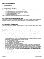 18
18
-
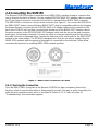 19
19
-
 20
20
-
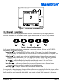 21
21
-
 22
22
-
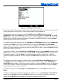 23
23
-
 24
24
-
 25
25
-
 26
26
-
 27
27
-
 28
28
-
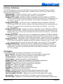 29
29
-
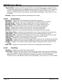 30
30
-
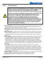 31
31
-
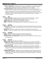 32
32
-
 33
33
-
 34
34
-
 35
35
-
 36
36
-
 37
37
-
 38
38
-
 39
39
-
 40
40
-
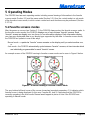 41
41
-
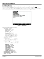 42
42
-
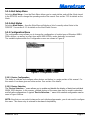 43
43
-
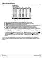 44
44
-
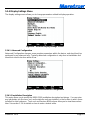 45
45
-
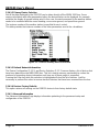 46
46
-
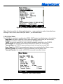 47
47
-
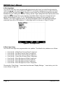 48
48
-
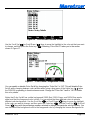 49
49
-
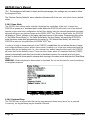 50
50
-
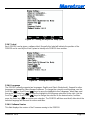 51
51
-
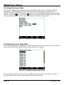 52
52
-
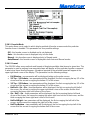 53
53
-
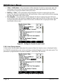 54
54
-
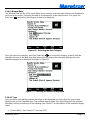 55
55
-
 56
56
-
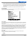 57
57
-
 58
58
-
 59
59
-
 60
60
-
 61
61
-
 62
62
-
 63
63
-
 64
64
-
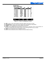 65
65
-
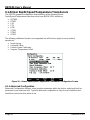 66
66
-
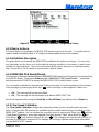 67
67
-
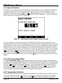 68
68
-
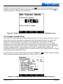 69
69
-
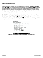 70
70
-
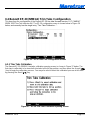 71
71
-
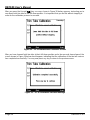 72
72
-
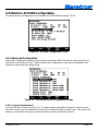 73
73
-
 74
74
-
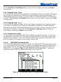 75
75
-
 76
76
-
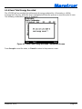 77
77
-
 78
78
-
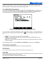 79
79
-
 80
80
-
 81
81
-
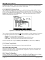 82
82
-
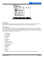 83
83
-
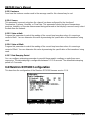 84
84
-
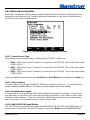 85
85
-
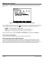 86
86
-
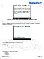 87
87
-
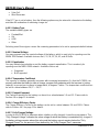 88
88
-
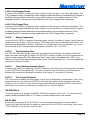 89
89
-
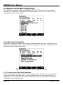 90
90
-
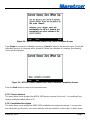 91
91
-
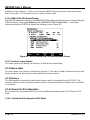 92
92
-
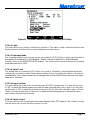 93
93
-
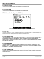 94
94
-
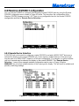 95
95
-
 96
96
-
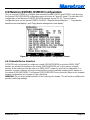 97
97
-
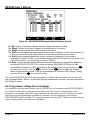 98
98
-
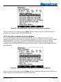 99
99
-
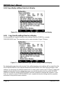 100
100
-
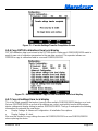 101
101
-
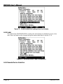 102
102
-
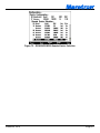 103
103
-
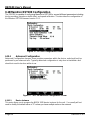 104
104
-
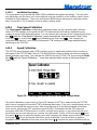 105
105
-
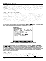 106
106
-
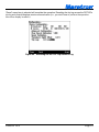 107
107
-
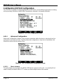 108
108
-
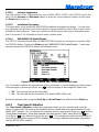 109
109
-
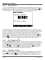 110
110
-
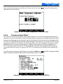 111
111
-
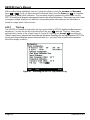 112
112
-
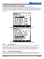 113
113
-
 114
114
-
 115
115
-
 116
116
-
 117
117
-
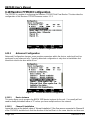 118
118
-
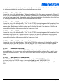 119
119
-
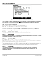 120
120
-
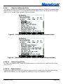 121
121
-
 122
122
-
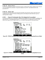 123
123
-
 124
124
-
 125
125
-
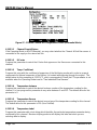 126
126
-
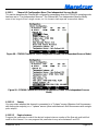 127
127
-
 128
128
-
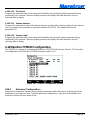 129
129
-
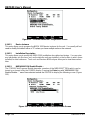 130
130
-
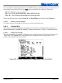 131
131
-
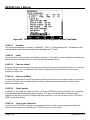 132
132
-
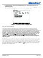 133
133
-
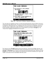 134
134
-
 135
135
-
 136
136
-
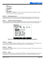 137
137
-
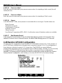 138
138
-
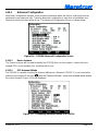 139
139
-
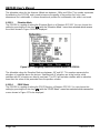 140
140
-
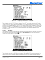 141
141
-
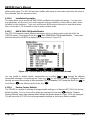 142
142
-
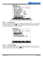 143
143
-
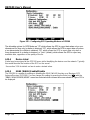 144
144
-
 145
145
-
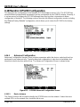 146
146
-
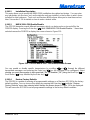 147
147
-
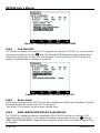 148
148
-
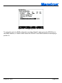 149
149
-
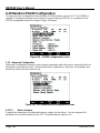 150
150
-
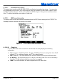 151
151
-
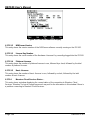 152
152
-
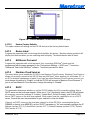 153
153
-
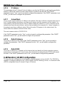 154
154
-
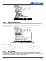 155
155
-
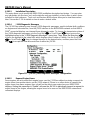 156
156
-
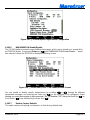 157
157
-
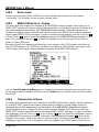 158
158
-
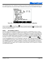 159
159
-
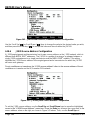 160
160
-
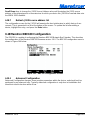 161
161
-
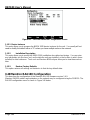 162
162
-
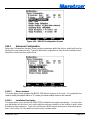 163
163
-
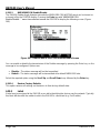 164
164
-
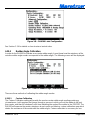 165
165
-
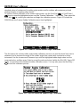 166
166
-
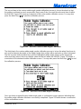 167
167
-
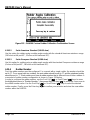 168
168
-
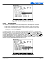 169
169
-
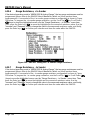 170
170
-
 171
171
-
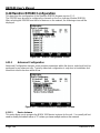 172
172
-
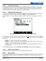 173
173
-
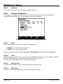 174
174
-
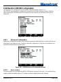 175
175
-
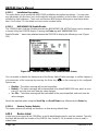 176
176
-
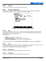 177
177
-
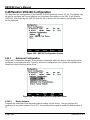 178
178
-
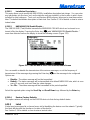 179
179
-
 180
180
-
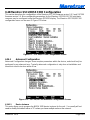 181
181
-
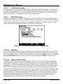 182
182
-
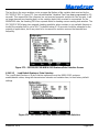 183
183
-
 184
184
-
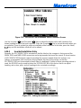 185
185
-
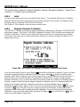 186
186
-
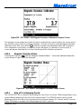 187
187
-
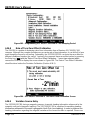 188
188
-
 189
189
-
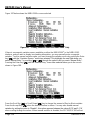 190
190
-
 191
191
-
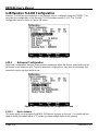 192
192
-
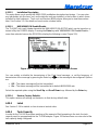 193
193
-
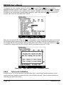 194
194
-
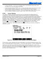 195
195
-
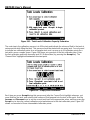 196
196
-
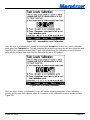 197
197
-
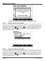 198
198
-
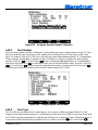 199
199
-
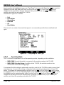 200
200
-
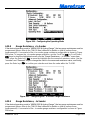 201
201
-
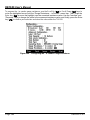 202
202
-
 203
203
-
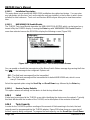 204
204
-
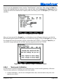 205
205
-
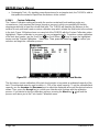 206
206
-
 207
207
-
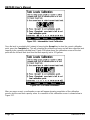 208
208
-
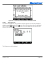 209
209
-
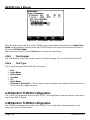 210
210
-
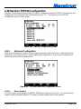 211
211
-
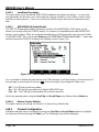 212
212
-
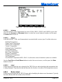 213
213
-
 214
214
-
 215
215
-
 216
216
-
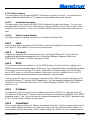 217
217
-
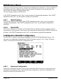 218
218
-
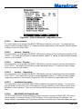 219
219
-
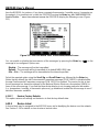 220
220
-
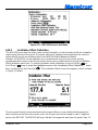 221
221
-
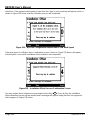 222
222
-
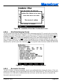 223
223
-
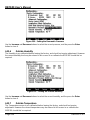 224
224
-
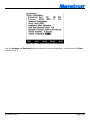 225
225
-
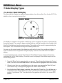 226
226
-
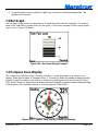 227
227
-
 228
228
-
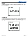 229
229
-
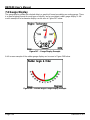 230
230
-
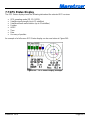 231
231
-
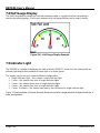 232
232
-
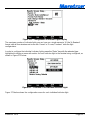 233
233
-
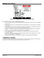 234
234
-
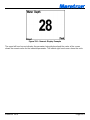 235
235
-
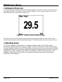 236
236
-
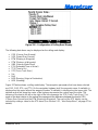 237
237
-
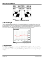 238
238
-
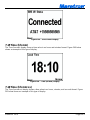 239
239
-
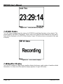 240
240
-
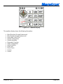 241
241
-
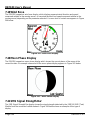 242
242
-
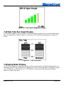 243
243
-
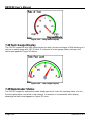 244
244
-
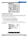 245
245
-
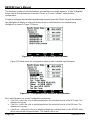 246
246
-
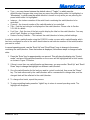 247
247
-
 248
248
-
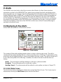 249
249
-
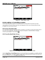 250
250
-
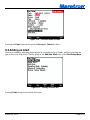 251
251
-
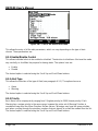 252
252
-
 253
253
-
 254
254
-
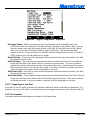 255
255
-
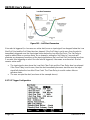 256
256
-
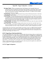 257
257
-
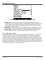 258
258
-
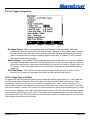 259
259
-
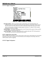 260
260
-
 261
261
-
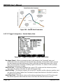 262
262
-
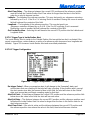 263
263
-
 264
264
-
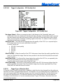 265
265
-
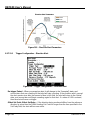 266
266
-
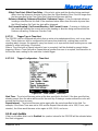 267
267
-
 268
268
-
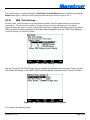 269
269
-
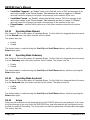 270
270
-
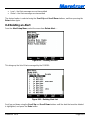 271
271
-
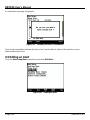 272
272
-
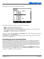 273
273
-
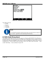 274
274
-
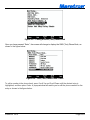 275
275
-
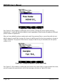 276
276
-
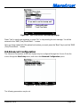 277
277
-
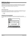 278
278
-
 279
279
-
 280
280
-
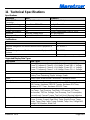 281
281
-
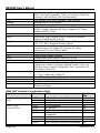 282
282
-
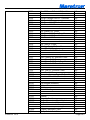 283
283
-
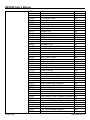 284
284
-
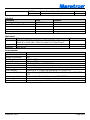 285
285
-
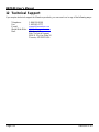 286
286
-
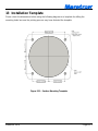 287
287
-
 288
288
-
 289
289


Maretron DSM150 User manual
- Type
- User manual
Ask a question and I''ll find the answer in the document
Finding information in a document is now easier with AI
Related papers
-
 Maretron DSM250 User manual
-
 Maretron DSM570 User manual
-
 Maretron MARE-004-10M-7 Installation guide
-
 Maretron DSM250-01 User manual
-
 Maretron SSC200 User manual
-
 Maretron SSC200 User manual
-
 Maretron DCR100 User manual
-
 Maretron RAA100 User manual
-
 Maretron CO-CO1224T Installation guide
-
 Maretron iS216 Installation guide


Other documents
-
 CruzPro MaxVu110 User manual
-
Lowrance electronic LMS-480DF User manual
-
 MGL Avionics FF-1 Operating instructions
-
Blue Sea Systems 1839 Operating instructions
-
Airmar DST810 CAST App User manual
-
 Setra Systems SRIMV Operating instructions
-
Furuno FI-504 User manual
-
-
-
Airmar GH2183 Owner's manual


