Page is loading ...


EB-6GSRD
User Guide Rev.0
PDS-061103 August 2015
2 of 22
Semtech
Proprietary & Confidential
www.semtech.com
Revision History
Contents
1. Hardware Components .................................................................................................................................5
1.1 SDI Inputs and Outputs ....................................................................................................................6
1.1.1 GSPI Interface...........................................................................................................................6
1.2 Power Supplies ....................................................................................................................................6
1.3 Jumpers ..................................................................................................................................................7
1.4 Switch Settings ....................................................................................................................................8
1.4.1 Balance Mode ..........................................................................................................................8
1.5 LED Indicators ......................................................................................................................................9
1.6 Optional Connectors .........................................................................................................................9
2. Getting Started .............................................................................................................................................. 10
2.1 Software Setup Instructions ........................................................................................................ 10
3. Schematics ...................................................................................................................................................... 16
4. Board Layout .................................................................................................................................................. 18
5. Bill of Materials............................................................................................................................................... 19
Version ECO Date Changes and/or Modifications
0 027070 August 2015 New document.

EB-6GSRD
User Guide Rev.0
PDS-061103 August 2015
3 of 22
Semtech
Proprietary & Confidential
www.semtech.com
General Description
The EB-6GSRD evaluation package is designed to accelerate the evaluation process of
the GS6152 (a multi-rate serial digital Re-clocker with 6Gb/s capability), the GS6042 (a
multi-rate Adaptive Cable Equalizer with 6Gb/s capability), and the GS6081 (a multi-rate
Cable Driver with 6Gb/s capability).
It is strongly recommended to read the GS6152 Data Sheet (PDS-060984) before using
this evaluation kit. Additionally, users should be familiar with the GS6042 Data Sheet
(PDS-060055) and the GS6081 Data Sheet (PDS-060046).
Evaluation Kit Contents
• Semtech EB-6GSRD Evaluation Board
• CD containing EB-6GSRD Evaluation Software, Drivers and Collateral
• 6' Micro USB Cable
Overview
Together with the EB-6GSRD Evaluation Board, this document serves as a guide for
evaluating the GS6152, GS6042 and GS6081 devices. This document contains five main
sections:
1. Hardware Components
2. Getting Started
3. Schematics
4. Board Layout
5. Bill of Materials
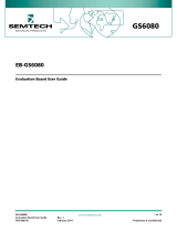
The figure below shows a block diagram of the features and the functions of the
EB-6GSRD.
The purpose of the EB-6GSRD dual-channel evaluation board is to evaluate the GS6152
6G video Reclocker (RCLK), the GS6042 6G Equalizer (EQ) and the GS6081 6G Cable
Driver (CD).
The GS6152 is designed to automatically recover the embedded clock from a SMPTE ST
2081-1 (proposed), SMPTE ST 424, SMPTE ST 292, or SMPTE ST 259-C compliant digital
video signal, and re-time the incoming video data. The GS6042 is designed to equalize
and restore signals received over 75Ω coaxial cable, and the GS6081 is designed to drive
non-inverted signals over two 75Ω coaxial cables.
The EB-6GSRD also provides access to the GS6152’s internal registers via GSPI.
Communication to the internal registers is provided via a Micro-USB port on the board
and the EB-6GSRD GUI.

EB-6GSRD
User Guide Rev.0
PDS-061103 August 2015
4 of 22
Semtech
Proprietary & Confidential
www.semtech.com
Block Diagram of the EB-6GSRD
GS6152
GS6042 GS6081
LEDs
SPI Control
Micro-USB Port
RCLK and CD
Control
BNC
BNC
BNC
SMA
SMA
SMA
SMA
Power Supply
DDI0
DDI1 DDO1/RCO
DDO0
Control Signal Path
SPI Control Path
Main Signal Path

EB-6GSRD
User Guide Rev.0
PDS-061103 August 2015
5 of 22
Semtech
Proprietary & Confidential
www.semtech.com
1. Hardware Components
Figure 1-1 and Figure 1-2 show the inputs, outputs and power connections for the
EB-6GSRD evaluation board.
Figure 1-1: EB-6GSRD Evaluation Board—Top View
Figure 1-2: EB-6GSRD Evaluation Board—Bottom View
JP5
JP1
JP2
JP4
JP3
SW3
SW2
SW1
Micro USB + Power
D2D3D4
GS6042
GS6152
GS6081
J8 (SDO1)
J9 (SDO2)
J10 (DDO)
J7 (DDO)
J1 (SDI)
J3 (DDI)
J4 (DDI)

EB-6GSRD
User Guide Rev.0
PDS-061103 August 2015
6 of 22
Semtech
Proprietary & Confidential
www.semtech.com
1.1 SDI Inputs and Outputs
The EB-6GSRD features a single-ended 75Ω input through a BNC connector J1 (SDI) and
one pair of 100Ω differential inputs through SMA connectors J3 and J4 (DDI, DDI
). On the
output side, the EB-6GSRD includes a pair of 100Ω differential outputs through SMA
connectors, J7 and J10 (DDO/RCO, DDO
/RCO) and two single-ended, non-inverted 75Ω
outputs through BNC connectors, J8 and J9 (SDO1, SDO2).
1.1.1 GSPI Interface
The EB-6GSRD features a GSPI interface via Micro-USB connection (J2) which is used to
access all of the GS6152 registers. The SPI interface is automatically enabled when the
Micro-USB is connected to a PC and the GUI is installed. The GS6152 registers will
maintain their settings until the board is powered-down, or reset via the SPI interface.
1.2 Power Supplies
The default power supply for the EB-6GSRD is provided by the Micro-USB while
connected to a PC (+5V). The Equalizer (GS6042) is powered by 1.8V and 3.3V. The
Reclocker (GS6152) is powered by +1.8V and 2.5V. The Cable Driver (GS6081) is powered
by +2.5V. There are +1.8V and +2.5V on-board regulators to power-up theses devices.
The board can also be powered-up externally by connecting a +5V power supply to TP1
(EXT5V) and TP2 (GND).
JP1, JP2, JP3, JP4 and JP5 need to be connected in order to power-up the board using
the on-board regulators.
Note: The power consumption of the EQ, RCLK and CD can be monitored by removing
JP1, JP2, JP3, JP4 and JP5, and supplying the correct voltages to the test points detailed
in Table 1-1.

EB-6GSRD
User Guide Rev.0
PDS-061103 August 2015
7 of 22
Semtech
Proprietary & Confidential
www.semtech.com
1.3 Jumpers
Table 1-1: Jumpers
Jumper Position Description
JP1
1.8V for Reclocker (RCLK_1V8) via
on-board power supply.
1.8V for Reclocker (RCLK_1V8) via
external power supply connected
to TP12.
JP2
1.8V for Equalizer (EQ_1V8) via
on-board power supply.
1.8V for Equalizer (EQ_1V8) via
external power supply connected
to TP13.
JP3
2.5V for Reclocker (RCLK_2V5) via
on-board power supply.
2.5V for Reclocker (RCLK_2V5) via
external power supply connected
to TP14.
JP4
2.5V for Cable Driver (CD_2V5) via
on-board power supply.
2.5V for Cable Driver (CD_2V5) via
external power supply connected
to TP15.
JP5
3.3V for Equalizer (EQ_3V3) via
on-board power supply.
3.3V for Equalizer (EQ_3V3) via
external power supply connected
to TP21.
Note: Removing the jumpers enables the user to monitor the exact power
consumption of the on-board devices via their respective test points.

EB-6GSRD
User Guide Rev.0
PDS-061103 August 2015
8 of 22
Semtech
Proprietary & Confidential
www.semtech.com
1.4 Switch Settings
There are three dip switch controls (SW1, SW2, SW3) populated on the board, with each
bit labelled on the silk screen. The switches configure the operating mode of the EQ,
Reclocker and Cable Driver. The signals can be set HIGH by placing the switch into the
“ON” position (closed).
Refer to Table 1-2 below for definitions of the switch settings.
1.4.1 Balance Mode
To enable Balance Mode, remove R60 and set SW3-1 in the open position, as well as
setting SW3-2 in the closed (ON) position.
Please see the GS6081 Data Sheet for more information on Balance Mode operation.
Table 1-2: Switch Positions
Switch
Position
Label Description HIGH (1) LOW (0)
SW1 Positions
SW1-1 DDI_SEL0 RCLK Input Select (0)
100Ω Differential Input
Selected
GS6042 Input Selected
SW1-2 DDO1_DIS RCLK DDO1 Disable SMA Output Disabled SMA Output Enabled
SW2 Positions
SW2-1 GAIN_SEL EQ Gain Select EQ Gain Enabled EQ Gain Disabled
SW2-2 BYPASS EQ Bypass EQ Bypass Enabled EQ Bypass Disabled
SW2-3 SLEEP_SW EQ Sleep EQ Sleep Enabled EQ Sleep Disabled
SW3 Positions
SW3-1 HD/SD Output Slew Rate Selection [1] HD Selected SD Selected
SW3-2 EQ_EN Trace EQ Enable [1] EQ Enabled EQ Disabled
SW3-3 SD01_DIS SD01 Output Disable SD01 Disabled SD01 Enabled
SW3-4 SD02_DIS SD02 Output Disable SD02 Disabled SD02 Enabled
Notes:
1. SW3-1 and SW3-2 should be in the open position to allow the GS6152 to control the Output Slew Rate Selection and Trace EQ Enable.

EB-6GSRD
User Guide Rev.0
PDS-061103 August 2015
9 of 22
Semtech
Proprietary & Confidential
www.semtech.com
1.5 LED Indicators
The EB-6GSRD features LED indicators which correspond to various status parameters of
the EQ, RCLK, CD and Micro-USB port. Refer to Table 1-3 below for descriptions of the
LED indicators.
1.6 Optional Connectors
The EB-6GSRD board also features additional test points. Table 1-4 below lists the test
points available on the board.
Table 1-3: EB-6GSRD LED Indicators
LED Name Description
D2 RCLK LOS
GS6152 Loss Of Signal status. Red when the input signal is not
present and off when the input signal is present.
D3 RCLK LOCK
GS6152 Lock Detect status signal. Green when the PLL is locked
and off when the PLL is not locked.
D4 OSP
GS6081 Output Signal status signal. Red when no signal is
present and off when signal is present.
D5
Micro-USB
Connection
Green when the Micro-USB is connected. Off when the USB
connection is terminated.
Table 1-4: EB-6GSRD Board Test Points
Test Point Name
TP3 DDI_SEL0
TP8 DDO1_DIS
TP4 RST
TP7 RCLK_LOCK
TP5 RCLK_LOS

EB-6GSRD
User Guide Rev.0
PDS-061103 August 2015
10 of 22
Semtech
Proprietary & Confidential
www.semtech.com
2. Getting Started
To evaluate the GS6152, please follow the steps listed below for a quick start-up.
• Install the EB-6GSRD software GUI
• Configure JP1, JP2, JP3, JP4 and JP5 to power-up the board via micro USB or
external power
• Connect J1 to an SDI source using a 75Ω coaxial cable of a supported length. Refer
to the GS6042 data sheet (DocID: PDS-060055) for details. You can also connect one
pair of 100Ω differential inputs through SMA connectors, J3 and J4 (DDI, DDI
)
• Monitor the SDI output through J8 or J9, or connect J7 and J10 to scope using 50Ω
coaxial cable
• Connect EB-6GSRD to a computer using micro USB cable
• Start the EB-6GSRD software GUI
• If required, the GS6152 registers can be modified using the provided GUI
2.1 Software Setup Instructions
Upon execution of the setup file that is contained within the CD, the following window
will appear as shown in Figure 2-1. To install the software you must click next and follow
the steps listed in the setup window.
Figure 2-1: Welcome Screen

EB-6GSRD
User Guide Rev.0
PDS-061103 August 2015
11 of 22
Semtech
Proprietary & Confidential
www.semtech.com
Click “I accept the agreement” as shown in Figure 2-2 and then click “Next”.
Figure 2-2: License Agreement
Before continuing with the setup, confirm that you meet the system requirements. Click
“Next”.
Figure 2-3: Software Requirements

EB-6GSRD
User Guide Rev.0
PDS-061103 August 2015
12 of 22
Semtech
Proprietary & Confidential
www.semtech.com
Now, select the destination where you would like the software GUI to be installed. Click
“Next”.
Figure 2-4: Select Destination Location
Next, select the start menu folder. Click “Next”.
Figure 2-5: Select Start Menu


EB-6GSRD
User Guide Rev.0
PDS-061103 August 2015
14 of 22
Semtech
Proprietary & Confidential
www.semtech.com
Lastly, check “Launch EB-6GSRD” and click “Finish” to complete the installation and
launch the GUI.
Figure 2-8: Finish Installation
Note: This application requires Microsoft .NET Framework 4.0 to be installed. It can be
downloaded from http://msdn.microsoft.com/en-ca/netframework/default.aspx. The
installer can also download the .NET framework automatically during the installation
process if an internet connection on the PC is available.
After finishing the setup, the main panel from the Semtech EB-6GSRD Host Control
Software will appear, as shown in Figure 2-9.


EB-6GSRD
User Guide Rev.0
PDS-061103 August 2015
16 of 22
Semtech
Proprietary & Confidential
www.semtech.com
3. Schematics
Figure 3-1: EB-6GSRD Board Schematic
(1.204V)
EQ SWITCH
RCK SWITCH
DNP
90Ω DIFF PAIR
POWER LED
EEPROM
NP
DNP
R58
10kΩ
FEMALE
GSPI
USB
DNP
DNP
MALE
DNP
DNP
DNP
100Ω IMPEDANCE
425mV (0dB)
CD SWITCH
ONLY POPULATE ONE
100Ω IMPEDANCE
TO BE POPULATED WITH 0R
GREEN
4.7μF
RCLK_1V8
GS6152
RCLK_1V8
4.7μF
SN74AUP1G07
SQ_ADJ
EQ_3V3
1μF
1kΩ
SMA
4.7μF
1kΩ
750Ω
SMA
CD_2V5
BNCRA
4.7nH
4.7nH
75Ω
4.7μF
3V3
FXL4TD245
SWDIP3
10μF
0Ω
470nF
10μF 10nF
NX8045GB
6MHz
5V
FT2232D
93C46B-I/SN
3V3
200Ω
ABM8G
27MHZ
18pF
0Ω
TBD
1kΩ
0Ω
WHITE
82.5Ω
75Ω
4.7μF
1μF
4.7μF
GS6081
100pF
10nF
GS6042
5V
5V
8pF
3V3
10nF
40 OHM
THSKT2X5
10nF
BNCRA
75Ω
0Ω
1MΩ
0Ω
33Ω
33Ω
THHDR2X5
3V3
3V3
33nF
27.0Ω
4.7μF
10nF
BNCRA
5V
3V3
3V3
GREEN
27.0Ω
0.35A
3V3
0Ω
4.7μF
100Ω
SWDIP2
SMTRARCPTUSBBMICRO
5V
75Ω
75Ω
37.4Ω
SMA
SMA
8pF
10nF
18pF
1μF
1V8
RCLK_1V8
RCLK_1V8
RCLK_2V5
10nF10nF
8.2nH
EQ_1V8
EQ_3V3
EQ_3V3
EQ_3V3EQ_3V3
0Ω
1kΩ
CD_2V5
CD_2V5
CD_2V5
RCLK_1V8
C57
100nF
R11
10kΩ
R10
10kΩ
R31
1kΩ
R57
R8
1kΩ
R9
1kΩ
R7
SW1
R67
24kΩ
R62
24kΩ
SW3
SWDIP4
R60
R1
2.61kΩ
R2
1.5kΩ
R34
1kΩ
TP7
TP5
R56
221Ω
SW2
R59
82Ω
D6
C22
100nF
U9
C21
10nF
C20
10nF
U4
C54
R53
R33
TP6
R20
J5
U6
L7
R55
0Ω
DNP
R39
33Ω
R54
0Ω
DNP
J7
J10
R38
R37
R32
R40
R41
0Ω
DNP
J6
C29
100nF
C24
100nF
J9
J8
J1
R22
470Ω
D5
U7
C35
C33C32
C31C30C28C25
TP4
R43
C37
C23
100nF
C19
100nF
R29
470Ω
C18
100nF
C14
100nF
C10
10μF
C15
R28
1.5kΩ
R25
R26
R27
Y1
C16
C17
U5
R24
2.20kΩ
L2
F1
R19
0Ω
DNP
R18
0Ω
DNP
J2
R16
10kΩ
U3
C9
100nF
R30
R36
R35
C42C41C36
L6
R50
C50
C46
10nF
C45
10nF
L4
1nH
L3
1nH
C43
10nF
C44
10nF
C49
R51
C47
R49
L5
R48
75Ω
R47
75Ω
R52
C48
R46
75Ω
R45
75Ω
R44
U8
C39
C38
C34 C40
R42
Y2
C27
C26
J4
J3
C13
R23
C12
C11
R21
L1
R17
2
2
2
DDO1_DIS
CSB
SCLK
MISO
MOSI
XTAL_BUFF_OUT
RCLK_LOCKED
RCLK_LOS
BYPASS
SLEEP_SW
CDB
OSP
RCLK_LOCKED
OSP
CD_DIS2B
DDO1_DIS
DDI_SEL0
GAIN_SEL
DDI_SEL0
OP_CTL
XTAL_BUFF_IN
OP_CTL
BYPASS
EXT PWR
RCLK_LOS
MOSI
CSB
MISO
EXT PWR
SCLK
CDB
GAIN_SEL
SLEEP
RCLK_LOS
XTAL_BUFF_IN
XTAL_BUFF_OUT
SLEEP_SW
CD_DIS1B
RCLK_LOCKED
1
14
43
3
4
2
1
5678
4321
1
1
4
5
6
3
2
1
2
1
4
5
1
3
2
12
1
13
16
TAB
8
14
2
3
9
4
11
10
15
7
6
5
10 9
87
6
5
43
21
16
1
TAB
7
10
15
2
9
8
11
12
13
14
6
5
4
3
32
1
32
1
109
8
7
6
5
43
21
1
2
1
2
1
2
2
1
17
16
18
24
39
35
32
29
48
23
46
37
38
28
36
47
42
TAB
20
19
21
27
45
44
26
25
13
12
9
6
3
41
40
31
30
34
33
15
10
11
7
8
4
5
1
2
22
2
1
44
43
31
14
42
3
7
8
47 26
10
5
4
41
34
25
18
9
1
2
48
32
33
35
36
37
38
39
40
27
28
29
30
46
45
16
17
19
20
21
22
23
24
11
12
13
15
6
21
1
SH6
SH5
SH4
SH3
SH2
SH1
4
5
2
3
5
8
6
7
4
3
1
2
13
4
8
1
TAB
10
9
12
11
15
5
14
16
7
6
2
3
4
3
2
1
32
1
32
1
TAB
VEE_CORE_48
VCC_CORE_47
VCO_FILT
VEE_CORE_43
VCC_CORE_42
VEE_DFT
VCC_DFT
VEE_DDO_32
VEE_DDO_35
VEE_DDO_29
VCC_DDO1
VSS_DIG
VDD_DIG
GND_9
GND_6
GND_3
LF-
LF+
DFT_CLKINP
DFT_CLKINN
VCO_DFT_FILT
VCC_DDO0
DDO0P
DDO0N
DDO1P
DDO1N
RST
GPIO3
GPIO2
CS
SCLK
SDOUT
SDIN
XTAL_BUF_OUT
XTAL_CLK_OUT
XTAL_CLK_IN
DDI_SEL1
DDI_SEL0/STROBE
GPIO1
GPIO0
DDI3N
DDI3P
DDI2N
DDI2P
DDI1N
DDI1P
DDI0N
DDI0P
SD/HD
VEE2
VEE1
VCC2
VCC1
TAB
OSP
EQ_EN
DISABLE2
DISABLE1
RSET
SDO2N
SDO2P
SDO1N
SDO1P
DDIN
DDIP
OUT
OUT
OUT
1
ON
1
ON
1
1
ON
1
A
Y
VCC
GND
NC
1
3
5
7
9
2
4
6
8
10
TAB
VCCB
GND
VCCA
T/R1
B0
B1
B2
B3
T/R2
OE
T/R3
A3
A2
A1
A0
T/R0
1
3
5
7
9
2
4
6
8
10
RA
RA
RA
1
AVCC
AGND
VCC_42
GND_34
VCCIOB
GND_25
GND_18
VCCIOA
GND_9
VCC_3
EECS
TEST
XTOUT
XTIN
PWREN
BDBUS0
BDBUS1
BDBUS2
BDBUS3
BDBUS4
BDBUS5
BDBUS6
BDBUS7
BCBUS0
BCBUS1
BCBUS2
BCBUS3
SI/WUB
ADBUS0
ADBUS1
ADBUS2
ADBUS3
ADBUS4
ADBUS5
ADBUS6
ADBUS7
ACBUS0
ACBUS1
ACBUS2
ACBUS3
SI/WUA
USBDM
USBDP
3V3OUT
RSTOUT
RESET
EEDATA
EESK
SHELL6
SHELL5
SHELL4
SHELL3
ID
SHELL2
SHELL1
GND
D+
D-
VBUS
VCC
VSS
NC_7
ORG
DO
DI
CLK
CS
TAB
VCC_A
CDSLEEP
VCC_OVEE_O
DDO
DDO
OP_CTL
SQ_ADJ
BYPASS
AGC
AGC
GAIN_SEL
SDI
SDI
VEE_A

EB-6GSRD
User Guide Rev.0
PDS-061103 August 2015
17 of 22
Semtech
Proprietary & Confidential
www.semtech.com
Figure 3-2: Power & Controls Schematic
RCLK LOS SIGNAL RCLK LOCK SIGNAL SP CABLE DRIVER
MMBT3904MMBT3904
GREENRED
2kΩ
LABEL
LABEL
BLACK
SC4215HSETRT
LABEL
LABEL
RCLK_2V5
LABEL
EQ_3V3
LABEL
THHDR1X2
PURPLE
LABEL
LABEL LABEL
C7
100nF
THHDR1X2
BLACK N/A
ADJ
SC4215ASTRT
MMBT3904
RED
RED
2V5
GREY
THHDR1X2
BLUE
YELLOW
THHDR1X2
1V8
ORANGE
220 OHM
RCLK_1V8
2kΩ
SC4215ASTRT
CD_2V5
2V5
EQ_1V8
600 OHM
C55
10μF
ADJ
10kΩ
5V
10kΩ10kΩ
ADJ
2kΩ
THHDR1X2
Q1 Q2
R3
D2 D3
TP2
TP1
TP3
TP15
TP13
TP12
TP21
TP14
TP10
L8
L9
C61
100nF
C60
100nF
C58
100nF
JP4
JP2
JP1
C53
100nF
C52
10μF
R64
8.45kΩ
R63
1.5kΩ
R5
R71R70R69
R68
R61
470Ω
C70
10μF
JP5
C65
10μF
C62
10μF
C63
100nF
U11
C51
10μF
JP3
R4
470Ω
Q3
D4
R6
470Ω
C1
10μF
C2
100nF
U1
R13
1.82kΩ
R12
7.32kΩ
C3
100nF
D1
C4
10μF
C5
10μF
C6
100nF
U2
R15
1.82kΩ
R14
4.75kΩ
11
OSP
RCLK_LOCKED
EXT PWR
RCLK_LOS
EXT PWR
2
3
1
21
2
1
21
21
1
3
2
21
63
TAB
4
1
5
8
72
21
1
2
1
3
2
2
1
63
TAB
4
1
5
8
72
21
63
TAB
4
1
5
8
72
C
B
E
C
B
E
TAB
GND
VIN
FB
VO
NC-5
NC_4
EN
NC_1
INININ
C
B
E
TAB
GND
VIN
FB
VO
NC-5
NC_4
EN
NC_1
TAB
GND
VIN
FB
VO
NC-5
NC_4
EN
NC_1
C59
10μF
C64
100nF
C56
100nF
C8
10μF


EB-6GSRD
User Guide Rev.0
PDS-061103 August 2015
19 of 22
Semtech
Proprietary & Confidential
www.semtech.com
5. Bill of Materials
Table 5-1: Bill Of Materials
Quantity Reference Description
10
C1, C4, C5, C8, C37, C42, C51,
C62, C65, C70
Capacitor; ceramic 10μF 6.3V 20% X5R 0603
8
C2, C3, C6, C7, C58, C61, C63,
C64
Capacitor; ceramic 0.1μF 6.3V 10% X5R 0402
12
C9, C14, C18, C19, C22, C23,
C24, C29, C53, C56, C57, C60
Capacitor; ceramic 0.1μF 16V 10% X7R 0402
1 C10 Capacitor; ceramic 10μF 10V X5R 0805
3 C11, C12, C35 Capacitor; ceramic 1.0μF 6.3V 20% X5R 0402
1 C13 Capacitor; ceramic 0.47μF 6.3V 10% X5R 0402
1C15
Capacitor; ceramic 0.033μF 6.3V 10% X5R
0402
2 C16, C17 Capacitor; ceramic 8pF 50V ±0.5pF C0G 0402
2 C20, C21
Capacitor; ceramic 10000pF 16V 10% X7R
0402
12
C25, C28, C30, C31, C32, C33,
C36, C41, C43, C44, C45, C46
Capacitor; ceramic 10000pF 25V 10% X7R
0402
8
C26, C27, C38, C39, C47, C48,
C49, C50
Capacitor; ceramic 4.7μF 6.3V 20% X5R 0402
2 C34, C40 Capacitor; ceramic RF 18pF 50V 5% C0G 0402
3 C52, C55, C59 Capacitor; ceramic 10μF 6.3V 20% X5R 0402
1 C54 Capacitor; ceramic 100pF 50V 5% C0G 0402
1 D1 Diode; Schottky 20V 3A SMA
2 D2, D4 LED; 1.6x0.8mm 625nm red CLR SMD
3 D3, D5, D6 LED; 1.6x0.8mm 568nm green CLR SMD
1 F1 Fuse; PTC RESET 6V 0.35A 1206
3 J1, J8, J9 Connector; 3G/HD RA BNC
1 J2 Connector; receptacle rev micro USB type B
4 J3, J4, J7, J10 Connector; SMA edge-mount
1J5
Connector; socket extended 10-position
0.100 DL gold
5 JP1, JP2, JP3, JP4, JP5 Connector; header 2-position 0.100 SGL gold
1 L1 Inductor; 8.2nH 540mA 0402
1 L2 Inductor; Ferrite 1.5A 40Ω 0805 SMD
2 L3, L4 Inductor; 1.0nH 300mA 0402
2 L5, L6 Inductor; 4.7nH 300mA 0402

EB-6GSRD
User Guide Rev.0
PDS-061103 August 2015
20 of 22
Semtech
Proprietary & Confidential
www.semtech.com
1 L7 Resistor; 0Ω 1/10W 5% 0402 SMD
1L8
Inductor; Ferrite Bead, chip, 220Ω @100MHz,
500mA,0.25Ω DCR 0603
1L9
Inductor; Ferrite Bead, chip, 600Ω @100MHz,
200mA,1Ω DCR 0603
3 Q1, Q2, Q3 Transistor; GP NPN AMP SOT23-3
1 R1 Resistor; 2.61kΩ 1/10W 1% 0402 SMD
3 R2, R28, R63 Resistor; 1.50kΩ 1/16W 1% 0402 SMD
3 R3, R5, R68 Resistor; 2kΩ 1/16W 0.1% 0402 SMD
5 R4, R6, R22, R29, R61 Resistor; 470Ω 1/16W 1% 0402 SMD
2 R7, R31, R34 Resistor; 1.00kΩ 1/16W 1% 0402 SMD
3 R8, R9, R43 Resistor; 1.00kΩ 1/16W 1% 0402 SMD
7
R10, R11, R16, R58, R69, R70,
R71
Resistor; 10.0kΩ 1/16W 1% 0402 SMD
1 R12 Resistor; 7.32kΩ 1/16W 1% 0402 SMD
2 R13, R15 Resistor; 1.82kΩ 1/16W 1% 0402 SMD
1 R14 Resistor; 4.75kΩ 1/16W 1% 0402 SMD
9
R17, R45, R46, R47, R48, R49,
R50, R51, R52
Resistor; 75.0Ω 1/16W 1% 0402 SMD
8
R18, R19, R30, R33, R40, R53,
R57, R60
Resistor; ZERO Ω 1/10W 5% 0402 SMD
1 R21 Resistor; 82.5Ω 1/16W 1% 0402 SMD
1 R23 Resistor; 37.4Ω 1/16W 1% 0402 SMD
1 R24 Resistor; 2.20kΩ 1/10W 1% 0402 SMD
2 R25, R26 Resistor; 27.0Ω 1/10W 1% 0402 SMD
1 R27 Resistor; 100Ω 1/16W 1% 0402 SMD
3 R37, R38, R39 Resistor; 33Ω 1/16W 0.5% 0402 SMD
1 R42 Resistor; 1.00MΩ 1/16W 1% 0402 SMD
1 R44 Resistor; 750Ω 1/16W 1% 0402 SMD
1 R56 Resistor; 221Ω 1/16W 1% 0402 SMD
1 R59 Resistor; 82Ω 1/16W 0.5% 0402 SMD
2 R62, R67 Resistor; 24kΩ 1% 1/10W 0402 SMD
1 R64 Resistor; 8.45kΩ 1/10W 1% 0402 SMD
1 SW1 Switch; tape seal 2-position SMD
1 SW2 Switch; tape seal 3-position SMD
1 SW3 Switch; tape seal 4-position SMD
Table 5-1: Bill Of Materials (Continued)
Quantity Reference Description
/