EB-GS3441
Evaluation Board User Guide
57256 - 0 June 2012
2 of 10
Contents
General Description ..........................................................................................................................................3
Evaluation Kit Contents ...................................................................................................................................3
Overview ..............................................................................................................................................................3
1. Evaluation Board User Guide ....................................................................................................................4
1.1 SDI Inputs and Outputs ..................................................................................................................4
1.2 Power ....................................................................................................................................................4
1.3 Switch Settings ..................................................................................................................................5
1.4 Jumper Settings .................................................................................................................................5
1.5 Potentiometer Settings ....................................................................................................................6
1.5.1 OP1_CTL, OP2_CTL Potentiometer Settings ................................................................6
1.5.2 Squelch Adjust (SQ_ADJ) Potentiometer Settings .....................................................6
1.6 LED Indicator .....................................................................................................................................7
2. Schematic .........................................................................................................................................................7
3. Board Layout...................................................................................................................................................8
4. Bill of Materials...............................................................................................................................................9
Version ECR Date Changes and / or Modifications
0 158256 June 2012 New document

EB-GS3441
Evaluation Board User Guide
57256 - 0 June 2012
3 of 10
General Description
The GS3441 evaluation package is designed to accelerate the evaluation process of the
GS3441 Adaptive Cable Equalizer.
It is strongly recommended to read the GS3441 Data Sheet (Doc ID: 56647) before using
this evaluation kit.
Evaluation Kit Contents
• Gennum EB-GS3441 Evaluation Board
• CD containing GS3441 collateral
Overview
The purpose of the EB-GS3441 Evaluation Board is to evaluate the GS3441 Extended
Reach 3G/HD/SD Adaptive Cable Equalizer with Dual Outputs. This device is designed
to support SMPTE ST 424, SMPTE ST 292 and SMPTE ST 259 serial digital video signals
standards, and is optimized for performance at 270Mb/s, 1.485Gb/s and 2.97Gb/s data
rates.
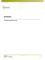
EB-GS3441 Functional Block Diagram
SW2 GS3441
Inputs
SMA
SMA
SMA
SMA
BNC
GS3441
IRL
GS3441 Power
Supply Connection
DDO1
DDO2

EB-GS3441
Evaluation Board User Guide
57256 - 0 June 2012
4 of 10
1. Evaluation Board User Guide
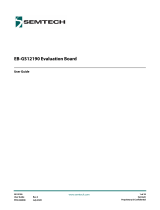
Figure 1-1 shows the inputs, outputs and power connections for the EB-GS3441.
Figure 1-1: GS3441 Evaluation Board (EB-GS3441)
1.1 SDI Inputs and Outputs
The GS3441 is a high-speed BiCMOS integrated circuit designed to equalize and restore
signals received over 75Ω co-axial cables. The EB-GS3441 is the evaluation board for the
GS3441. The EB-GS3441 features one 75Ω single-ended input through a BNC connector
(SDI/J4), and two pairs of 100Ω differential outputs (DDO1/J5, DDO1
/J6 and DDO2/J7,
DDO2
/J8) through SMA connectors.
1.2 Power
The EB-GS3441 features four power posts (3V3, GND, VCCO1, VCCO2). By default, the
GS3441 can be powered with a single power supply connected to 3.3V. Alternatively,
the GS3441 outputs can be powered using a second and third power supply connected
to VCCO1 and VCCO2. The power configuration jumpers VCCO1_SEL and VCCO2_SEL
must be configured accordingly.
When the outputs are powered separately, the voltage supplied to VCCO1 and VCCO2
can be set between 1.2V and 3.3V.
502
DC
502
DC
ON CTS
219
010
1 2 3 4
502
DC
GS3441
XXXXE3
YYWW
50Ω DIFFERENTIAL
OUTPUTS
3.3V STEADY SUPPLY EXTERNAL SUPPLY
75Ω SINGLE-ENDED
INPUT
CD INDICATOR
ENABLE JUMPER
CARRIER DETECT
INDICATOR
GAIN SELECT
SWITCH SETTING
BYPASS SWITCH
SETTING
Output 1 and 2 Enable
SWITCH SETTING
Legend
Capacitor (Cx)
Resistor (Rx)
Inductor (Lx)

EB-GS3441
Evaluation Board User Guide
57256 - 0 June 2012
5 of 10
1.3 Switch Settings
A four-point dip switch (SW2) provides the GS3441’s input selection. The switch
positions are marked on the silkscreen, and are described in Table 1-1 below:
1.4 Jumper Settings
The jumpers on the EB-GS3441 board are described in the following tables:
Table 1-1: SW1 Settings
Switch Label Switch OFF Description Switch ON Description
GS 0
Gain Select off, no change in gain
(default)
1 Gain Select on, 6dB gain
OP2EN 0 OUTPUT2 disabled 1 OUTPUT2 enabled (default)
OP1EN 1 OUTPUT1 enabled (default) 0 OUTPUT1 disabled
BP 0 Bypass off (default) 1 Bypass on
Table 1-2: AUTOSLEEP (JP7) Jumper Settings
Label Connection Description
Connected (default) Enables the AUTOSLEEP function
Unconnected Disables the AUTOSLEEP function
Table 1-3: VCCO1_SEL (JP8), VCCO2_SEL (JP9) Jumper Settings
Label Connection Description
SS (default) Shared supply mode
EXT Output uses a separate external supply

EB-GS3441
Evaluation Board User Guide
57256 - 0 June 2012
6 of 10
1.5 Potentiometer Settings
Adjusting the potentiometers clockwise will decrease the voltage level at the SQ_ADJ
and OP_CTL pins. Adjusting the potentiometers counter-clockwise will increase the
voltage level at the SQ_ADJ and OP_CTL pins.
1.5.1 OP1_CTL, OP2_CTL Potentiometer Settings
The output control potentiometer settings are described in Table 1-5 below:
1.5.2 Squelch Adjust (SQ_ADJ) Potentiometer Settings
There is one multi-turn potentiometer on the EB-GS3441 assigned for squelch adjust,
which adjusts the voltage seen at the SQ_ADJ pin. This input adjusts the threshold of the
CD
pin. When the SQ_ADJ input is 0V, all cable lengths will be equalized. When the
SQ_ADJ input is 3.3V, there will be no equalization regardless of the cable length. Please
refer to the GS3441 Data Sheet for more details on carrier detect and squelch adjust.
Table 1-4: LED_EN (JP10) Jumper Settings
Label Connection Description
Connected (default)
LED is enabled
Unconnected
LED is disabled
Table 1-5: OP1_CTL, OP2_CTL Input Settings
Level Swing De-emphasis Mute Voltage
0 800mV Off N 0.000 - 0.083
1 800mV 2dB N 0.234 - 0.394
2 800mV 4dB N 0.545 - 0.704
3 800mV 6dB N 0.856 - 1.015
4 400mV Off N 1.166 - 1.333
5 400mV 2dB N 1.484 - 1.644
6 400mV 4dB N 1.795 - 1.954
7 400mV 6dB N 2.106 - 2.265
8 400mV N/A Y 2.416 - 2.500

EB-GS3441
Evaluation Board User Guide
57256 - 0 June 2012
7 of 10
1.6 LED Indicator
D3 is the Carrier Detect LED for the GS3441. D3 is on when no carrier is detected and
stays off otherwise. There is one LED_EN jumper which when disconnected, it disables
the LED. This is useful when measuring system power dissipation.
2. Schematic
Figure 2-1: GS3441 Schematic
5
6
7
8
4
3
2
1
1516
2
1219
1
TAB
9
3
4
10
11
21
20
5
14
13
18
17
22
8
7
6
OP2_EN_41
BYPASS_41
OP1_EN_41
BYPASS_41
CDB_93
24
23
VCC_DIG_41 - Digital supply
Power Supplies
LED enable jumper
VCC_O2_41 - Output 2 supply
VCC_A_41 - Input supply
AUTOSLEEP
Power Supplies
VCC_O1_41 - Output 1 supply
VCC_LED_41 - LED supply separated from input supply by header
10μF
100nF
10μF
100nF
VCC_O2_41
VCC_O1_41
100nF
37.4Ω
VCC_A_41
4.7μF
SMA
SWDIP4
VCC_DIG_41
221Ω
VCC_DIG_41
VCC_O1_41
75Ω
WHITE
10nF
WHITE
SMA
100Ω
BLACK
VCC_A_41
RED
WHITE
470nF
VCC_A_41
SMA
10nF
1μF
10NF
1μF
10nF
VCC_A_41
10nF
VCC_O2_41
SMA
4.7μF
MMBT3904
VCC_A_41
75Ω
4.7μF
VCC_A_41
RED
14kΩ
4.7μF
365Ω
YELLOW
1.21kΩ
GS3441
DNP
4.7nH
BNC
4.7nH
5.0kΩ
YELLOW
5.0kΩ
10nF
WHITE
5.0kΩ
R33
D3
R34
Q6
R31
C17
TP7
TP8
C34
C32
C31
C33
TP11
TP10
JP9
JP8
JP10
C35
C36
TP13
TP12
SW2
C23
C24
C25
R30
R32
R23
TP9
C18
C29
J8
C28
J7
J5
J6
C26
C27
C19
C20
R18
L4
R16
R17
L3
R15
J4
C21
U1
TP6
C16
JP7
TAB
CD
SLEEP
CLI
OP1_EN
OP1_CTL
VCC_O1
DDO1
DDO1
VEE_O1
VEE_O2
DDO2
DDO2
VCC_O2
OP2_CTL
OP2_EN
SQ_ADJ
BYPASS
AGC
AGC
GAIN_SEL
SDI
SDI
VEE_A
VCC_A
1
ON
1
2
3
1
2
3
C
B
E
1
2
3
3
2
1
3
2
1
2
1
2
1
10μF
R10
R11

EB-GS3441
Evaluation Board User Guide
57256 - 0 June 2012
8 of 10
3. Board Layout
Figure 3-1: Layer 1 (Top Layer) and Top Silkscreen Figure 3-2: Layer 2 (Ground)
Figure 3-3: Layer 3 (Power) Figure 3-4: Layer 4 (Bottom)

EB-GS3441
Evaluation Board User Guide
57256 - 0 June 2012
9 of 10
4. Bill of Materials
Table 4-1: Bill of Materials
Quantity Reference Designator Part
6 C16, C17, C18, C23, C24,
C25
Capacitor, ceramic; 10,000pF, 16V, 10%, X7R 0402
2 C19, C20 Capacitor, ceramic; 1.0μF, 10V, X5R 0402
1 C21 Capacitor, ceramic; 0.47μF, 10V, X5R 0402
4 C26, C27, C28, C29 Capacitor, ceramic; 4.7μF, 10V, 10%, X5R 0603
3 C31, C32, C35 Capacitor, ceramic; 0.1μF, 16V, 10%, X7R 0603
3 C33, C34, C36 Capacitor, tantalum; 10μF, 10V, 10%, 3216/1206
1D3 LED, red; SMD type 0603
1J4 Connector; BNC, edge-mount, PCB
(Cambridge C-SX-077)
4 J5, J6, J7, J8 Connector; SMA, edge-mount, short signal pin
(Johnson 142-0791-881)
2 JP8, JP9 Connector; header 2mm single straight 36-position
(3 positions used)
2 JP7, JP10 Connector; header 2mm single straight 36-position
(2 positions used)
2 L3, L4 Inductor; 4.7nH, 300mA, 0402
1 Q6 Transistor; GP NPN AMP SOT23-3
1 R10 Resistor; 365Ω, 1/16W, 1%, 0402 SMD
2 R15, R16 Resistor; 75.0Ω, 1/16W, 1%, 0402 SMD
1 R11 Resistor; 1.21kΩ, 1/16W, 1%, 0402 SMD
1 R23 Resistor; 221Ω, 1/16W, 1%, 0402 SMD
1 R18 Resistor; 37.4Ω, 1/16W, 1%, 0402 SMD
1 R33 Resistor; 14.0kΩ, 1/16W, 1%, 0402 SMD
1 R34 Resistor; 100Ω, 1/16W, 1%, 0402 SMD
3 R30, R31, R32 Potentiometer; 5.0kΩ 1/4W 10% 4mm cermet top
SMD 5-turn
1 SW2 Switch; tape seal 4-position SMD
4 TP6, TP7, TP8, TP9 Test Point, PC multi-purpose (white)
2 TP10, TP11 Test Point, PC multi-purpose (yellow)
1 TP12 Test Point, PC multi-purpose (red)
1 TP13 Test Point, PC multi-purpose (black)
1 U1 Gennum GS3441 3Gb/s Equalizer,
QFN24-4X4X1MM-0P5MM

© Semtech 2011
All rights reserved. Reproduction in whole or in part is prohibited without the prior written consent of the copyright
owner. The information presented in this document does not form part of any quotation or contract, is believed to be
accurate and reliable and may be changed without notice. No liability will be accepted by the publisher for any
consequence of its use. Publication thereof does not convey nor imply any license under patent or other industrial or
intellectual property rights. Semtech assumes no responsibility or liability whatsoever for any failure or unexpected
operation resulting from misuse, neglect improper installation, repair or improper handling or unusual physical or
electrical stress including, but not limited to, exposure to parameters beyond the specified maximum ratings or
operation outside the specified range.
SEMTECH PRODUCTS ARE NOT DESIGNED, INTENDED, AUTHORIZED OR WARRANTED TO BE SUITABLE FOR USE IN
LIFE-SUPPORT APPLICATIONS, DEVICES OR SYSTEMS OR OTHER CRITICAL APPLICATIONS. INCLUSION OF SEMTECH
PRODUCTS IN SUCH APPLICATIONS IS UNDERSTOOD TO BE UNDERTAKEN SOLELY AT THE CUSTOMER’S OWN RISK.
Should a customer purchase or use Semtech products for any such unauthorized application, the customer shall
indemnify and hold Semtech and its officers, employees, subsidiaries, affiliates, and distributors harmless against all
claims, costs damages and attorney fees which could arise.
Notice: All referenced brands, product names, service names and trademarks are the property of their respective owners
.
DOCUMENT IDENTIFICATION
EVALUATION BOARD USER GUIDE
Information relating to this product and the application or design described
herein is believed to be reliable, however such information is provided as a
guide only and Semtech assumes no liability for any errors in this document, or
for the application or design described herein. Semtech reserves the right to
make changes to the product or this document at any time without notice.
EB-GS3441
Evaluation Board User Guide
57256 - 0 June 2012
10 of 10
10
Contact Information
Semtech Corporation
Gennum Products Division
200 Flynn Road, Camarillo, CA 93012
Phone: (805) 498-2111, Fax: (805) 498-3804
www.semtech.com
CAUTION
ELECTROSTATIC SENSITIVE DEVICES
DO NOT OPEN PACKAGES OR HANDLE EXCEPT AT A
STATIC-FREE WORKSTATION
/