Page is loading ...

sec.1c
−−−−
1
DOOR PHONE SYSTEMSBASIC SYSTEM DIAGRAMS
DOOR PHONE - VIDEO DOOR PHONE SYSTEMS: Installation Diagrams
BASIC DIAGRAMS FOR
TRADITIONAL CALL
DOOR PHONE SYSTEMS
SECTION 1C
(REV.C)
Download from:
www.urmetdomus.com
Technical Manuals area
index on page 10

2
−−−−
sec.1c
BASIC SYSTEM DIAGRAMS
DOOR PHONE - VIDEO DOOR PHONE SYSTEMS: Installation Diagrams
DOOR PHONE SYSTEMS
CONNECTION OF DOOR PHONES TO 1 OUTDOOR STATION
5
5
4+(n-2)
4+(n-1)
4+n
9+n
2
FUNCTION
This is certainly the most common type of door phone system.
Press a button on the panel outside the building door to make the
buzzer of the corresponding door phone ring. Lift the handset of the
called door phone to establish a conversation with the door unit.
Simply fully press the handset hook to operate the electrical door
lock.
Using the door phone Ref. 1130/55 must press the button no the
handset to estabilish a conversation with the door unit; simply picking
up the handset is not suffi cient.
The advantage is that any handsets left accidentally off-hook do not
interfer with the optimal operation of the other door phones.
EQUIPMENT
The following devices are needed for the system illustrated in diagram
SC101-1247A:
DOOR PHONE REFERENCES
N. X Door phones Mod. 1130 Ivory colour Ref. 1130
White colour Ref. 1130/50
or
N. X Door phones Mod. 1130
with insertion key White colour Ref. 1130/55
POWER SUPPLY FOR DOOR PHONE SYSTEM REFERENCES
N. 1 Power supply for
door phone system 28VA Ref. 786/11
OUTDOOR STATION REFERENCES
Sinthesi model
N. X Button modules Ref. 1145/11-/12-/13-/14
N. 1 Module with door unit set-up Ref. 1145/20-/21-/22
N. 1 Amplifi ed door unit Ref. 1145/500
The panels must be installed in fl ush-mounting boxes with
module holder frames or in cases with hood for wall-mounted
versions. Refer to “Sinthesi panel” section of Doorphone and
Videodoorphone system - product technical manual.
or
K-Steel model
N. X Button modules Ref. 1155/11-/12A-/13A-/14A
N. 1 Module with door unit Ref. 1155/20-/21-/22A
The panels must be installed in fl ush-mounting boxes with
module holder frames or in cases with hood for wall-mounted
versions. Refer to “K-Steel modular vandal-proof panel” section
of Doorphone and Videodoorphone system - product technical
manual.
or
725 model
N. 1 Panel with N buttons Mod. 725
N. 1 Amplifi ed door unit Ref. 1128/500
For the panels references and the accessories refer to “Panels
with anodized Aluminium front plate Mod. 725” section of
Doorphone and Videodoorphone system - product technical
manual.
or
1128 model
N. 1 Front case for door unit Ref. 1128/20-/21
N. 1 Door unit Ref. 1128/500
N. X Front case Ref. 1128/10-/11
N. X Button Ref. 1128/1-/2
For boards of accessories refer to “Wall Mounted Panel
Mod. 1128” section of Doorphone and Videodoorphone system
product technical manual.
DIAGRAM NOTES
(see section 1)
C4.001
C4.004
C4.007
C4.008
VX.014

sec.1c
−−−−
3
DOOR PHONE SYSTEMSBASIC SYSTEM DIAGRAMS
DOOR PHONE - VIDEO DOOR PHONE SYSTEMS: Installation Diagrams
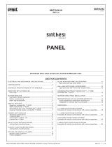
CONNECTION OF DOOR PHONES TO 1 OUTDOOR STATION
SC101-1247A
COLUMN
(C4.007)
(C4.008)
(C4.004)
(VX.014)
LIGHT BULB
TRANSFORMER
~
~
~12
~0
2
1
6
9
8
10
11
7
-
1A
1
2
L
+
~12
~0
G/T
~0
~12
U2
G/T
U1PS
-6
~
~18
+6
~0
~12
-J
~
U2
U3
U4
U1
~12
~0
~12
G/T
~0
G/T
2
1
6
9
8
10
11
7
MAIN ~
MAIN ~
Name tag
lighting
Name tag
lighting
ELECTRIC
LOCK
Lock
Release
POWER SUPPLY
FOR DOOR
PHONE SYSTEM

4
−−−−
sec.1c
BASIC SYSTEM DIAGRAMS
DOOR PHONE - VIDEO DOOR PHONE SYSTEMS: Installation Diagrams
DOOR PHONE SYSTEMS
CONNECTION OF SEVERAL DOOR PHONES TO 2 OUTDOOR STATIONS
5
5
4+(n-2)
4+(n-1)
4+n
7+n 7+n
22
FUNCTION
This type of installation solves the problem to connect a series of door
phones of a building with 2 entrances each one equipped with a push
button panel.
This solution permits, by simply pushing a button from one of the 2
push button panels, to connect automatically the user to the calling
push button panels unhooking the handset. This type of installation
does not allow to talk from both outdoor stations simultaneously, since
they work alternatively.
EQUIPMENT
The following devices are needed for the system illustrated in diagram
SC101-0440B:
DOOR PHONE REFERENCES
N. X Door phones Mod. 1130 Ivory colour Ref. 1130
White colour Ref. 1130/50
POWER SUPPLY FOR DOOR PHONE SYSTEM REFERENCES
N. 1 Power supply for
door phone system 28VA Ref. 786/11
N. 1 Relay box Ref. 788/51
OUTDOOR STATION REFERENCES
Sinthesi model
N. X Button modules Ref. 1145/11-/12-/13-/14
N. 2 Module with door unit set-up Ref. 1145/20-/21-/22
N. 2 Amplifi ed door unit Ref. 1145/500
The panels must be installed in fl ush-mounting boxes with
module holder frames or in cases with hood for wall-mounted
versions. Refer to “Sinthesi panel” section of Doorphone and
Videodoorphone system - product technical manual.
or
K-Steel model
N. X Button modules Ref. 1155/11-/12A-/13A-/14A
N. 2 Module with door unit Ref. 1155/20-/21-/22A
The panels must be installed in fl ush-mounting boxes with
module holder frames or in cases with hood for wall-mounted
versions. Refer to “K-Steel modular vandal-proof panel” section
of Doorphone and Videodoorphone system - product technical
manual.
or
725 model
N. 2 Panel with N buttons Mod. 725
N. 2 Amplifi ed door unit Ref. 1128/500
For the panels references and the accessories refer to “Panels
with anodized Aluminium front plate Mod. 725” section of
Doorphone and Videodoorphone system - product technical
manual.
or
1128 model
N. 2 Front case for door unit Ref. 1128/20-/21
N. 2 Door unit Ref. 1128/500
N. X Front case Ref. 1128/10-/11
N. X Button Ref. 1128/1-/2
For boards of accessories refer to “Wall Mounted Panel
Mod. 1128” section of Doorphone and Videodoorphone system
product technical manual.
DIAGRAM NOTES
(see section 1)
C4.001
C4.007
C4.008
VX.014

sec.1c
−−−−
5
DOOR PHONE SYSTEMSBASIC SYSTEM DIAGRAMS
DOOR PHONE - VIDEO DOOR PHONE SYSTEMS: Installation Diagrams
CONNECTION OF SEVERAL DOOR PHONES TO 2 OUTDOOR STATIONS
SC101-0440B
COLUMN
(C4.008)
(C4.007)
(C4.008)
(C4.007)
(VX.014)
13
SN1
1
4
10
7
1C2C
~
12
~
6
8
SN2
0
9
1
5
2
14
3
15
112
-
1A
1
2
L
+
~12
~0
G/T
~0
~12
U2
G/T
U1
2
1
6
9
8
10
11
7
-
1A
1
2
L
+
G/T
~0
G/T~12
~0
U2
U1
~12
-
6
~ ~ +
0621 J
-PS~~
~
0
~
21
~~
~0
~12
U4
U2
U1
~12 U3
G/T
~0
G/T
2
1
6
9
8
10
11
7
U2
U3
U4
U1
~12
~0
~12
G/T
~0
G/T
RELAY
BOX
Lock
Release
Lock
Release
ELECTRIC
LOCK
ELECTRIC
LOCK
MAIN ~
MAIN ~
Name tag
lighting
Name tag
lighting
Name tag
lighting
LIGHT BULB
TRANSFORMER
POWER SUPPLY
FOR DOOR
PHONE SYSTEM

6
−−−−
sec.1c
BASIC SYSTEM DIAGRAMS
DOOR PHONE - VIDEO DOOR PHONE SYSTEMS: Installation Diagrams
DOOR PHONE SYSTEMS
CONNECTION OF SEVERAL DOOR PHONES TO 3 OR 4 OUTDOOR STATIONS
5+n
6
5+(n-1)
6
5+(n-2)
22
7+n 7+n
22
7+n 7+n
FUNCTION
This installation allows connection of a series of door phone to 3 or 4
push button panels.
By simply pushing a button on one of the 4 panels, the called door
phone, picking up the handset, is automatically connected with the
calling push button panel.
It is not possible to talk from the outdoor stations simultaneously, since
they work alternatively.
EQUIPMENT
The following devices are needed for the system illustrated in diagram
SC101-0441C
:
DOOR PHONE REFERENCES
N. X Door phones Mod. 1130 Ivory colour Ref. 1130
White colour Ref. 1130/50
POWER SUPPLY FOR DOOR PHONE SYSTEM REFERENCES
N. 1 Power supply for
door phone system 28VA Ref. 786/11
N. 1 Relay box Ref. 788/58
OUTDOOR STATION REFERENCES
Sinthesi model
N. X Button modules Ref. 1145/11-/12-/13-/14
N. 4 Module with door unit set-up Ref. 1145/20-/21-/22
N. 4 Amplifi ed door unit Ref. 1145/500
The panels must be installed in fl ush-mounting boxes with
module holder frames or in cases with hood for wall-mounted
versions. Refer to “Sinthesi panel” section of Doorphone and
Videodoorphone system - product technical manual.
or
K-Steel model
N. X Button modules Ref. 1155/11-/12A-/13A-/14A
N. 4 Module with door unit Ref. 1155/20-/21-/22A
The panels must be installed in fl ush-mounting boxes with
module holder frames or in cases with hood for wall-mounted
versions. Refer to “K-Steel modular vandal-proof panel” section
of Doorphone and Videodoorphone system - product technical
manual.
or
725 model
N. 4 Panel with N buttons Mod. 725
N. 4 Amplifi ed door unit Ref. 1128/500
For the panels references and the accessories refer to “Panels
with anodized Aluminium front plate Mod. 725” section of
Doorphone and Videodoorphone system - product technical
manual.
or
1128 model
N. 4 Front case for door unit Ref. 1128/20-/21
N. 4 Door unit Ref. 1128/500
N. X Front case Ref. 1128/10-/11
N. X Button Ref. 1128/1-/2
For boards of accessories refer to “Wall Mounted Panel
Mod. 1128” section of Doorphone and Videodoorphone system
product technical manual.
DIAGRAM NOTES
(see section 1)
C4.001
C4.007
C4.008
VX.014

sec.1c
−−−−
7
DOOR PHONE SYSTEMSBASIC SYSTEM DIAGRAMS
DOOR PHONE - VIDEO DOOR PHONE SYSTEMS: Installation Diagrams
CONNECTION OF SEVERAL DOOR PHONES TO 3 OR 4 OUTDOOR STATIONS
SC101-0441B
(C4.007)
(C4.008)
(C4.007)
(C4.008)
(C4.007)
(C4.008)
(C4.007)
(C4.008)
POWER SUPPLY
FOR HOUSE
PHONE SYSTEM
LIGHT BULB
TRANSFORMER
(VX.014)
2
1
6
9
8
10
11
7
L
+
2
-
1
1A
U1
G/T ~12
~0
~12
G/T
~0
U2
G/T
~0
~12
~0
~12U2
U1
G/T
U3
U4
~
0
~
21
~~
2
1
6
9
8
10
11
7
G/T
~0
~12
~0
~12 U2
U1
G/T
U3
U4
L
+
2
-
1
1A
U1
G/T~12
~0
~12
G/T
~0
U2
L
+
2
-
1
1A
U1
G/T ~12
~0
~12
G/T
~0
U2
III
III
1
2
SN3
III
AP
12
II
II
2
1
SN2
II
AP
III
-
-
II
1C 2C0-
~ ~
21
IV
1
2
IV
SN4
AP
IV
I
I
1
2
SN1
AP
I
-
IV
I
-
PA
G/T
~0
~12
~0
~12U2
U1
G/T
U3
U4
G/T
~0
~12
~0
~12 U2
U1
G/T
U3
U4
~
~0
-6
PS
-J
~12
+6
~18
~
L
+
2
-
1
1A
U1
G/T~12
~0
~12
G/T
~0
U2
TO THE FOLLOWING
DOOR PHONES
TO THE FOLLOWING
MODULES
TO THE FOLLOWING
MODULES
TO THE FOLLOWING
MODULES
ELECTRIC LOCK ELECTRIC LOCK
Name tag
lighting
Name tag
lighting
MAIN~
MAIN~
Lock
Release
TO THE FOLLOWING
MODULES
ELECTRIC LOCK
Name tag
lighting
Name tag
lighting
Lock
Release
Lock
Release
ELECTRIC LOCK
Name tag
lighting
Lock
Release
RELAY
BOX

8
−−−−
sec.1c
BASIC SYSTEM DIAGRAMS
DOOR PHONE - VIDEO DOOR PHONE SYSTEMS: Installation Diagrams
DOOR PHONE SYSTEMS
K= quantity of columns
4+n 4+n
4+(n-1) 4+(n-1)
55
55
4+(n-2) 4+(n-2)
6
9+n 5+n 9+n5+n
5+K+n
8+K+
n+n...
2
2
2
CONNECTION OF SEVERAL COLUMNS OF DOOR PHONES TO 1 MAIN
OUTDOOR STATION
Each column is also connected to its own outdoor station
FUNCTION
It is the ideal solution for residential centers where the single villas
have to be connected to both their own outdoor stations and a common
one at the main entrance.
During the call the concerned door phone is automatically switched to
the common outdoor station or to the one of the group it belongs to, by
means of a switching relay.
Services towards secondary outdoor stations are independent and can
therefore take place at the same time.
When the call comes from the common outdoor station, only the group
the called door phone belongs to is switched to it, the others being
able to carry on the normal service with their own secondary outdoor
stations.
EQUIPMENT
The following devices are needed for the system illustrated in diagram
SC101-0461B:
DOOR PHONE REFERENCES
N. X Door phones Mod. 1130 Ivory colour Ref. 1130
White colour Ref. 1130/50
POWER SUPPLY FOR DOOR PHONE SYSTEM REFERENCES
N. K+1 Power supply for
door phone system 28VA Ref. 786/11
N. K Relay box Ref. 788/51
N. K Call repeater relay Ref. 788/52
OUTDOOR STATION REFERENCES
Sinthesi model
N. X Button modules Ref. 1145/11-/12-/13-/14
N. K+1 Module with door unit set-up Ref. 1145/20-/21-/22
N. K+1 Amplifi ed door unit Ref. 1145/500
The panels must be installed in fl ush-mounting boxes with
module holder frames or in cases with hood for wall-mounted
versions. Refer to “Sinthesi panel” section of Doorphone and
Videodoorphone system - product technical manual.
or
K-Steel model
N. X Button modules Ref. 1155/11-/12A-/13A-/14A
N. K+1 Module with door unit Ref. 1155/20-/21-/22A
The panels must be installed in fl ush-mounting boxes with
module holder frames or in cases with hood for wall-mounted
versions. Refer to “K-Steel modular vandal-proof panel” section
of Doorphone and Videodoorphone system - product technical
manual.
or
725 model
N. K+1 Panel with N buttons Mod. 725
N. K+1 Amplifi ed door unit Ref. 1128/500
For the panels references and the accessories refer to “Panels
with anodized Aluminium front plate Mod. 725” section of
Doorphone and Videodoorphone system - product technical
manual.
or
1128 model
N. K+1 Front case for door unit Ref. 1128/20-/21
N. K+1 Door unit Ref. 1128/500
N. X Front case Ref. 1128/10-/11
N. X Button Ref. 1128/1-/2
For boards of accessories refer to “Wall Mounted Panel
Mod. 1128” section of Doorphone and Videodoorphone system
product technical manual.
DIAGRAM NOTES
(see section 1)
C4.001
C4.007
C4.008

sec.1c
−−−−
9
DOOR PHONE SYSTEMSBASIC SYSTEM DIAGRAMS
DOOR PHONE - VIDEO DOOR PHONE SYSTEMS: Installation Diagrams
SC101-0461B
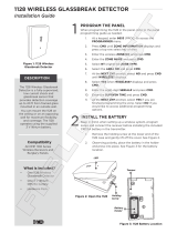
CONNECTION OF SEVERAL COLUMNS OF DOOR PHONES TO 1 MAIN
OUTDOOR STATION
Each column is also connected to its own outdoor station
2nd COLUMN1st COLUMN
(C4.008)
(C4.007)
(C4.008)
(C4.007)
SN1
4
1
-6
7
LIGHT BULB
TRANSFORMER
(VX.014)
SN1
7
1
4
-6
U4
U2
G/T
U1
U3
G/T
~0
~0
~12
~12
G/T
~0
~0
~12
~12
U3
U1
U4
U2
G/T
G/T
~0
~0
~12
~12
U3
U1
U4
U2
G/T
+
1A
L
1
2
-
G/T
~0
~12
~0
~12U2
U1
G/T
U3
U4
2
1
6
9
8
10
11
7
2
1
6
9
8
10
11
7
~ ~0 -6 +6~12~
S2
C
6
~0
~12
S3
S1
2
CA
G/T
~0
~12
~0
~12U2
U1
G/T
U3
U4
L
+
2
-
U1
G/T ~12
~0
~12
G/T
~0
U2
1
1A
~-6 ~0~12 +6 ~ ~
0
~
21
~~
3
SN2
825
6
~
13
0
9
15
1
SN1
4
14
7
10
11
12
~
21CC21
U4
U2
G/T
U1
U3
G/T
~0
~0
~12
~12
G/T
~0
~0
~12
~12
U3
U1
U4
U2
G/T
U4
U2
G/T
U1
U3
G/T
~0
~0
~12
~12
RELAY
BOX
Lock
Release
Lock
Release
ELECTRIC
LOCK
ELECTRIC
LOCK
MAIN ~
MAIN ~
MAIN ~
POWER SUPPLY
FOR DOOR
PHONE SYSTEM
POWER SUPPLY
FOR DOOR
PHONE SYSTEM
TO THE FOLLOWING
MODULES
TO THE FOLLOWING
MODULES
Name tag
lighting
Name tag
lighting
Name tag
lighting
CONNECTION AS
1ST GROUP
CALL
REPEATER RELAY
TO THE FOLLOWING
COLUMN
Calls
Common

I
−−−−
sec.1c
SECTION 1C CONTENTS
DOOR PHONE AND VIDEO DOOR PHONE SYSTEM - DIAGRAM
DOOR PHONE AND VIDEO DOOR PHONE SYSTEM - DIAGRAM -
Section 1
C
DOOR PHONE - VIDEO DOOR PHONE SYSTEMS: Installation Diagrams
Diagram Sec. Pag.
BASIC DIAGRAMS FOR TRADITIONAL CALL DOOR PHONE SYSTEMS
CONNECTION OF DOOR PHONES TO 1 OUTDOOR STATION ................................................................SC101-1247A..............1c................2
CONNECTION OF SEVERAL DOOR PHONES TO 2 OUTDOOR STATIONS ............................................SC101-0440B ..............1c ................4
CONNECTION OF SEVERAL DOOR PHONES TO 3 OR 4 OUTDOOR STATIONS...................................SC101-0441C ..............1c................6
CONNECTION OF SEVERAL COLUMNS OF DOOR PHONES TO 1 MAIN OUTDOOR STATION
Each column is also connected to its own outdoor station ............................................................................SC101-0461B ..............1c................8

sec.1c
−−−−
II
SECTION 1C CONTENTS
DOOR PHONE AND VIDEO DOOR PHONE SYSTEM - DIAGRAM
DOOR PHONE AND VIDEO DOOR PHONE SYSTEM - DIAGRAM -
Section 1
C
DOOR PHONE - VIDEO DOOR PHONE SYSTEMS: Installation Diagrams
TRADITIONAL CALL DOOR PHONE SYSTEM DIAGRAM CROSS-REFERENCE TABLE
LIST OF AVAILABLE FUNCTIONS
Number of main panels to be installed
Number of secondary panels to be installed
DIAGRAM DESCRIPTION PAG
CONNECTION OF DOOR PHONES TO 1 OUTDOOR STATION 2
CONNECTION OF SEVERAL COLUMNS OF DOOR PHONES TO 1 MAIN OUTDOOR STATION
Each column is also connected to its own outdoor station 8
CONNECTION OF SEVERAL DOOR PHONES TO 2 OUTDOOR STATIONS 4
CONNECTION OF SEVERAL DOOR PHONES TO 3 OR 4 OUTDOOR STATIONS 6
DIAGRAM
SC101-1247A
SC101-0461B
SC101-0440B
SC101-0441C
K = number of columns with panel
NOTE: The diagrams shown in this table can be made using Sinthesi, K-Steel, 725 panel models.
1
1
2
4
0
K
0
0
/