Page is loading ...

BASIC SYSTEM DIAGRAMS
sec.1a
−−−−
1
DOOR PHONE SYSTEMS
DOOR PHONE - VIDEO DOOR PHONE SYSTEMS: Installation Diagrams
BASIC DIAGRAMS FOR 4+N WIRE
DOOR PHONE SYSTEMS
SECTION 1A
(REV.D)
Download from:
www.urmetdomus.com
Technical Manuals area
index on page 62

BASIC SYSTEM DIAGRAMS
2
−−−−
sec.1a
DOOR PHONE SYSTEMS
DOOR PHONE - VIDEO DOOR PHONE SYSTEMS: Installation Diagrams
EQUIPMENT
The following devices are needed for the system illustrated in diagram
SC101-0858C:
“4+N” DOOR PHONE KIT DIAGRAMS
N. X One-family kit (1 button) Ref. 1129/501
consisting of:
• Smyle panel 1 button with built-in door unit.
• 1 Atlantico door phone (with door opener button and 1
additional button).
• Power transformer: Ref. 9000/230 (230Vac-18VA, 3 DIN
modules).
or
N. 1 Two-family kit (2 buttons) Ref. 1129/502
consisting of:
• Smyle panel 2 buttons with built-in door unit.
• 2 Atlantico door phones (with door opener button and 1
additional button).
• Power transformer: Ref. 9000/230 (230Vac-18VA, 3 DIN
modules).
DIAGRAM NOTES
(see section 1)
C4.001
(*) door phone included in two-family kit only
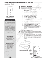
CONNECTION OF UP TO 2 DOOR PHONES TO 1 DOOR UNIT
5
5
6
8
2
(*)
FUNCTION
Pressing one of the external panel buttons, the bitonal electronic
call is sent to the correspondent door phone loudspeaker. When the
called door phone handset is unhooked, contact is established and
conversation may take place. To operate the electric lock it is suffi cient
to press the proper push button.
PS
1
1A
2
~
-/~
~12
~0
CA
1
2
6
9
10
CA
1
2
6
9
10
~0
~
~
~12
(*)
POWER SUPPLY
Lock Release
MAIN ~
ELECTRIC
LOCK
SC101-0858C

BASIC SYSTEM DIAGRAMS
sec. 1a
−−−−
3
DOOR PHONE SYSTEMS
DOOR PHONE - VIDEO DOOR PHONE SYSTEMS: Installation Diagrams
CONNECTION OF UP TO 2 DOOR PHONES TO 1 DOOR UNIT
FUNCTION
Pressing one of the external panel buttons, the bitonal electronic
call is sent to the correspondent door phone loudspeaker. When the
called door phone handset is unhooked, contact is established and
conversation may take place. To operate the electric lock it is suffi cient
to press the proper push button.
EQUIPMENT
The following devices are needed for the system illustrated in diagram
SC101-1259B:
“4+N” DOOR PHONE KIT DIAGRAMS
N. 1 One-family kit (1 button) Ref. 1133/301
consisting of:
• Sinthesi door unit module with 1 call button Ref. 1145/21
• Door unit Ref. 1145/500
• 1 Atlantico door phone Ref. 1133/1
• 1 fl ush mounting box for 1 module Ref 1145/51
• Module holder with frame for 1 module Ref. 1145/61
• Power unit 230Vac-28VA, 3 DIN modules Ref. 786/11
or
N. 1 Two-family kit (2 buttons) Ref. 1133/302
consisting of:
• Sinthesi door unit module with 2 call buttons Ref. 1145/22
• Door unit Ref. 1145/500
• 2 Atlantico door phones Ref. 1133/1
• 1 fl ush mounting box for 1 module Ref 1145/51
• Module holder with frame for 1 module Ref. 1145/61
• Power unit 230Vac-28VA, 3 DIN modules Ref. 786/11
DIAGRAM NOTES
(see section 1)
C4.001
(*) door phone included in two-family kit only
Posto
Esterno
CA
1
2
6
10
9
G/T
T1
T1
-J
-6
+6
~0
~
~12
PS
~
CA
1
2
6
10
9
G/T
T1
T1
L
+
2
-
1A
1
U1
G/T ~12
G/T
~0
~0
~12
U2
(*)
POWER SUPPLY
Lock Release
MAIN ~
MODULE FOR DOOR UNIT
ELECTRIC
LOCK
SC101-1259B
5
5
6
8
2
(*)

BASIC SYSTEM DIAGRAMS
4
−−−−
sec.1a
DOOR PHONE SYSTEMS
DOOR PHONE - VIDEO DOOR PHONE SYSTEMS: Installation Diagrams
CONNECTION OF SEVERAL DOOR PHONES TO 1 DOOR UNIT
Door phone with or without insertion key
5
5
4+(n-2)
4+(n-1)
4+n
9+n
2
FUNCTION
Pressing one of the external panel buttons, the bitonal electronic
call is sent to the correspondent door phone loudspeaker. When the
called door phone handset is unhooked, contact is established and
conversation may take place. To operate the electric lock it is suffi cient
to press the proper push button.
EQUIPMENT
The following devices are needed for the system illustrated in diagram
SC101-1133C:
DOOR PHONE REFERENCES
N. X Door phone Mod. Utopia Grey colour Ref. 1134/1
or
N. X Door phone Mod. Atlantico White colour Ref. 1133
or
N. X Door phone Mod. Atlantico
wiht insertion key White colour Ref. 1133/10
POWER SUPPLY FOR DOOR PHONE SYSTEM REFERENCES
N. 1 Power supply for
door phone system 28VA Ref. 786/11
OUTDOOR STATION REFERENCES
Sinthesi model
N. X Button modules Ref. 1145/11-/12-/13-/14
N. 1 Module with door unit set-up Ref. 1145/20-/21-/22
N. 1 Amplifi ed door unit Ref. 1145/500
The panels must be installed in fl ush-mounting boxes with
module holder frames or in cases with hood for wall-mounted
versions. Refer to “Sinthesi panel” section of Doorphone and
Videodoorphone system - product technical manual.
or
K-Steel model
N. X Button modules Ref. 1155/11-/12A-/13A-/14A
N. 1 Module with door unit Ref. 1155/20-/21-/22A
The panels must be installed in fl ush-mounting boxes with
module holder frames or in cases with hood for wall-mounted
versions. Refer to “K-Steel modular vandal-proof panel” section
of Doorphone and Videodoorphone system - product technical
manual.
or
725 model
N. 1 Panel with N buttons Mod. 725
N. 1 Amplifi ed door unit Ref. 1128/500
For the panels references and the accessories refer to “Panels
with anodized Aluminium front plate Mod. 725” section of
Doorphone and Videodoorphone system - product technical
manual.
or
1128 model
N. 1 Front case for door unit Ref. 1128/20-/21
N. 1 Door unit Ref. 1128/500
N. X Front case Ref. 1128/10-/11
N. X Button Ref. 1128/1-/2
For boards of accessories refer to “Wall Mounted Panel
Mod. 1128” section of Doorphone and Videodoorphone system -
product technical manual.

BASIC SYSTEM DIAGRAMS
sec.1a
−−−−
5
DOOR PHONE SYSTEMS
DOOR PHONE - VIDEO DOOR PHONE SYSTEMS: Installation Diagrams
CONNECTION OF SEVERAL DOOR PHONES TO 1 DOOR UNIT
Door phone with or without insertion key
SC101-1133C
(C4.004)
Name tag
lighting
(C4.007)
(C4.008)
TO THE FOLLOWING
DOOR PHONES
(C4.006)
6
1
9
2
10
CA
G/T
~0
~12
~0
~12U2
U1
G/T
U3
U4
6
1
9
2
10
CA
-J
-6
+6
~0
~12
~
~
PS
L
+
2
-
1A
1
U1
G/T ~12
~0
~12
G/T
~0
U2
POWER SUPPLY
FOR DOOR
PHONE SYSTEM
Lock Release
MAIN ~
TO THE FOLLOWING
MODULE
ELECTRIC
LOCK
DIAGRAM NOTES
(see section 1)
C4.001
C4.004
C4.006
Sinthesi models only:
Connect jumper L with G/T.
C4.007 C4.008

BASIC SYSTEM DIAGRAMS
6
−−−−
sec.1a
DOOR PHONE SYSTEMS
DOOR PHONE - VIDEO DOOR PHONE SYSTEMS: Installation Diagrams
CONNECTION OF 6 DOOR PHONES TO 1 DOOR UNIT
Door phones A and B are called individually
while door phones C-D-E-F are called in parallel
A
B
C
D
E
F
12
2
7
6
5
5
5
5
5
5
5
5
5
5
PARALLEL CALLS
SINGLE CALLS
FUNCTION
By pressing U1 or U2 on the panel inside the building, a two-tone
electronic call is sent to the speaker or door phone A or door phone B,
respectively.
By pressing U3 on the panel, door phones C-D-E-F are all called at the
same time.
Lift the handset of the called door phones to establish a conversation
with the door unit. Simply press the corresponding button to release
the electrical door lock.
EQUIPMENT
The following devices are needed for the system illustrated in diagram
SC101-1273A:
DOOR PHONE REFERENCES
N. 6 Door phone Mod. Utopia Grey colour Ref. 1134/1
or
N. 6 Door phone Mod. Atlantico White colour Ref. 1133
POWER SUPPLY FOR DOOR PHONE SYSTEM REFERENCES
N. 1 Power supply for
door phone system 28VA Ref. 786/11
OUTDOOR STATION REFERENCES
Sinthesi model
N. 1 Button modules Ref. 1145/13
N. 1 Module with door unit set-up Ref. 1145/20
N. 1 Amplifi ed door unit Ref. 1145/500
The panels must be installed in fl ush-mounting boxes with
module holder frames or in cases with hood for wall-mounted
versions. Refer to “Sinthesi panel” section of Doorphone and
Videodoorphone system - product technical manual.
or
K-Steel model
N. 1 Button modules Ref. 1155/13A
N. 1 Module with door unit Ref. 1155/20
The panels must be installed in fl ush-mounting boxes with
module holder frames or in cases with hood for wall-mounted
versions. Refer to “K-Steel modular vandal-proof panel” section
of Doorphone and Videodoorphone system - product technical
manual.
or
725 model
N. 1 Panel with 3 buttons Ref. 1155/13A
N. 1 Amplifi ed door unit Ref. 1128/500
or
1128 model
N. 1 Front case for door unit Ref. 1128/20-/21
N. 1 Door unit Ref. 1128/500
N. 3 Button Ref. 1128/1-/2
N. 3 Blank module (*) Ref. 1128/30-/31
(*) for small button installation only
For boards of accessories refer to “Wall Mounted Panel
Mod. 1128” section of Doorphone and Videodoorphone system -
product technical manual.
DIAGRAM NOTES
(see section 1)
C4.001
C4.004
C4.006
Sinthesi models only:
Connect jumper L with G/T.
C4.008

BASIC SYSTEM DIAGRAMS
sec.1a
−−−−
7
DOOR PHONE SYSTEMS
DOOR PHONE - VIDEO DOOR PHONE SYSTEMS: Installation Diagrams
CONNECTION OF 6 DOOR PHONES TO 1 DOOR UNIT
Door phones A and B are called individually
while door phones C-D-E-F are called in parallel
SC101-1273A
(C4.004)
(C4.008)
POWER SUPPLY
FOR HOUSE
PHONE SYSTEM
A
B
C
D
E
F
PARALLEL CALLS
(C4.006)
6
1
9
2
10
CA
6
1
9
2
10
CA
G/T
~0
~12
~0
~12U1
U2
U3
G/T
L
+
2
-
1A
1
6
1
9
2
10
CA
6
1
9
2
10
CA
6
1
9
2
10
CA
6
1
9
2
10
CA
-J
-6
+6
~0
~12
~
~
PS
MAIN~
SINGLE CALLS
Name tag
lighting
Lock Release
ELECTRIC
LOCK

BASIC SYSTEM DIAGRAMS
8
−−−−
sec.1a
DOOR PHONE SYSTEMS
DOOR PHONE - VIDEO DOOR PHONE SYSTEMS: Installation Diagrams
CONNECTION OF 6 DOOR PHONES TO 1 DOOR UNIT
Door phones A and B are called individually while door phones C-D-E-F are called
in parallel. Floor call service with differentiated tone.
Possibility of timing the door open
A
B
C
D
E
F
12
2
8
7
5
6
6
6
6
5
5
5
5
5
PARALLEL CALL
SINGLE CALLS
FUNCTION
By pressing U1 or U2 on the panel inside the building, a two-tone
electronic call is sent to the speaker or door phone A or door phone B,
respectively.
By pressing U3 on the panel, door phones C-D-E-F are all called at the
same time.
Lift the handset of the called door phones to establish a conversation
with the door unit.
Each apartment is equipped with a fl oor call button which will operate
the ringer with a differentiated call tone with respect to that of the door
unit.
Simply press the corresponding button to release the electrical door
lock (operation can be timed).
EQUIPMENT
The following devices are needed for the system illustrated in diagram
SC101-1284A:
DOOR PHONE REFERENCES
N. 6 Door phone Mod. Utopia Grey colour Ref. 1134/1
or
N. 6 Door phone Mod. Atlantico White colour Ref. 1133
POWER SUPPLY FOR DOOR PHONE SYSTEM REFERENCES
N. 1 Power supply for
door phone system 28VA Ref. 786/13
OUTDOOR STATION REFERENCES
Sinthesi model
N. 1 Button modules Ref. 1145/13
N. 1 Module with door unit set-up Ref. 1145/20
N. 1 Amplifi ed door unit Ref. 1145/500
The panels must be installed in fl ush-mounting boxes with
module holder frames or in cases with hood for wall-mounted
versions. Refer to “Sinthesi panel” section of Doorphone and
Videodoorphone system - product technical manual.
or
K-Steel model
N. 1 Button modules Ref. 1155/13A
N. 1 Module with door unit Ref. 1155/20
The panels must be installed in fl ush-mounting boxes with
module holder frames or in cases with hood for wall-mounted
versions. Refer to “K-Steel modular vandal-proof panel” section
of Doorphone and Videodoorphone system - product technical
manual.
or
725 model
N. 1 Panel with 3 buttons Ref. 1155/13A
N. 1 Amplifi ed door unit Ref. 1128/500
or
1128 model
N. 1 Front case for door unit Ref. 1128/20-/21
N. 1 Door unit Ref. 1128/500
N. 3 Button Ref. 1128/1-/2
N. 3 Blank module (*) Ref. 1128/30-/31
(*) for small button installation only
For boards of accessories refer to “Wall Mounted Panel
Mod. 1128” section of Doorphone and Videodoorphone system -
product technical manual.
DIAGRAM NOTES
(see section 1)
C4.001
C4.006
Sinthesi models only:
Connect jumper L with G/T.
C4.008
VD.007

BASIC SYSTEM DIAGRAMS
sec.1a
−−−−
9
DOOR PHONE SYSTEMS
DOOR PHONE - VIDEO DOOR PHONE SYSTEMS: Installation Diagrams
CONNECTION OF 6 DOOR PHONES TO 1 DOOR UNIT
Door phones A and B are called individually while door phones C-D-E-F are called
in parallel. Floor call service with differentiated tone.
Possibility of timing the door open
SC101-1284A
(C4.008)
(C4.006)
A
B
C
D
E
F
(VD.007)
(VD.007)
(VD.007)
(VD.007)
(VD.007)
(VD.007)
6
1
9
2
10
CA
6
1
9
2
10
CA
6
1
9
2
10
CA
6
1
9
2
10
CA
6
1
9
2
10
CA
+
1
L
1A
2
-
U2
G/T
U1
U3
G/T
~0
~0
~12
~12
6
1
9
2
10
CA
-J
-6
+6
~0
~12
PS
~
~
SE1
AP
SE2
PS2
POWER SUPPLY
FOR HOUSE
PHONE SYSTEM
PARALLEL CALLS
MAIN~
SINGLE CALLS
Name tag
lighting
Lock Release
ELECTRIC
LOCK

BASIC SYSTEM DIAGRAMS
10
−−−−
sec.1a
DOOR PHONE SYSTEMS
DOOR PHONE - VIDEO DOOR PHONE SYSTEMS: Installation Diagrams
CONNECTION OF SEVERAL DOOR PHONES TO 2 OUTDOOR STATIONS
Use the relay box Ref. 788/51 and the power supply Ref. 786/11
5
5
4+(n-2)
4+(n-1)
4+n
7+n 7+n
22
FUNCTION
This type of installation solves the problem to connect a series of
house phones of a building with 2 entrances each one equipped with
a push button panel.
This solution permits, by simply pushing a button from one of the 2
push button panels, to connect automatically the user to the calling
push button panels unhooking the handset. This type of installation
does not allow to talk from both outdoor stations simultaneously, since
they work alternatively.
EQUIPMENT
The following devices are needed for the system illustrated in diagram
SC101-1217C:
DOOR PHONE REFERENCES
N. X Door phone Mod. Utopia Grey colour Ref. 1134/1
or
N. X Door phone Mod. Atlantico White colour Ref. 1133
POWER SUPPLY AND RELAY REFERENCES
N. 1 Power supply for
door phone system 28VA Ref. 786/11
N. 1 Relay box Ref. 788/51
OUTDOOR STATION REFERENCES
Sinthesi model
N. X Button modules Ref. 1145/11-/12-/13-/14
N. 2 Module with door unit set-up Ref. 1145/20-/21-/22
N. 2 Amplifi ed door unit Ref. 1145/500
The panels must be installed in fl ush-mounting boxes with
module holder frames or in cases with hood for wall-mounted
versions. Refer to “Sinthesi panel” section of Doorphone and
Videodoorphone system - product technical manual.
or
K-Steel model
N. X Button modules Ref. 1155/11-/12A-/13A-/14A
N. 2 Module with door unit Ref. 1155/20-/21-/22A
The panels must be installed in fl ush-mounting boxes with
module holder frames or in cases with hood for wall-mounted
versions. Refer to “K-Steel modular vandal-proof panel” section
of Doorphone and Videodoorphone system - product technical
manual.
or
725 model
N. 2 Panel with N buttons Mod. 725
N. 2 Amplifi ed door unit Ref. 1128/500
For the panels references and the accessories refer to “Panels
with anodized Aluminium front plate Mod. 725” section of
Doorphone and Videodoorphone system - product technical
manual.
or
1128 model
N. 2 Front case for door unit Ref. 1128/20-/21
N. 2 Door unit Ref. 1128/500
N. X Front case Ref. 1128/10-/11
N. X Button Ref. 1128/1-/2
For boards of accessories refer to “Wall Mounted Panel
Mod. 1128” section of Doorphone and Videodoorphone system -
product technical manual.
DIAGRAM NOTES
(see section 1)
C4.001
C4.006
Sinthesi models only:
Connect jumper L with G/T.
C4.007 C4.008 C4.016
VX.014

BASIC SYSTEM DIAGRAMS
sec.1a
−−−−
11
DOOR PHONE SYSTEMS
DOOR PHONE - VIDEO DOOR PHONE SYSTEMS: Installation Diagrams
CONNECTION OF SEVERAL DOOR PHONES TO 2 OUTDOOR STATIONS
Use the relay box Ref. 788/51 and the power supply Ref. 786/11
SC101-1217C
(C4.006)
(C4.007)
~ ~
(C4.007)
(C4.008)
(C4.007)
(C4.008)
(C4.006)
(VX.014)
~0
~12
~
~
6
1
9
2
10
CA
L
+
2
-
1A
1
U1
G/T ~12
~0
~12
G/T
~0
U2
6
1
9
2
10
CA
G/T
~0
~12
~0
~12U2
U1
G/T
U3
U4
28
SN1
~0
7
1
15
13
1C2C
14
SN2
9
3
5
64
1012
11
~12
G/T
~0
~12
~0
~12 U2
U1
G/T
U3
U4
L
+
2
-
1A
1
U1
G/T~12
~0
~12
G/T
~0
U2
~0-6 ~12+6PS
TO THE FOLLOWING
MODULE
Lock
Release
Name tag
lighting
Name tag
lighting
MAIN ~
MAIN ~
ELECTRIC
LOCK
TO THE FOLLOWING DOOR PHONES
TO THE FOLLOWING
MODULE
POWER SUPPLY
FOR DOOR
PHONE SYSTEM
Lock
Release
Name tag
lighting
ELECTRIC
LOCK
RELAY
LIGHT BULB
TRANSFORMER

BASIC SYSTEM DIAGRAMS
12
−−−−
sec.1a
DOOR PHONE SYSTEMS
DOOR PHONE - VIDEO DOOR PHONE SYSTEMS: Installation Diagrams
CONNECTION OF SEVERAL DOOR PHONE TO 2 DOOR UNITS
Differentiated calls from door units.
Use the power supply wiht relay Ref. 786/15
4+n
5
4+(n-1)
5
4+(n-2)
22
7+n 7+n
FUNCTION
This type of system solves the problem of connecting a door phone
column in a building with two entrances, each of which equipped with
one panel and respective door unit.
In this solution, a visitor can simply press a button on either of the
two panels. The called door phone user can pick up the call and
automatically connect to the calling panel. The other panel will be cut
off.
As a consequence, it is not possible in such as system to speak to two
door units at the same time because either one or the other will be cut
off.
The user can recognise which door unit generated the call thanks to
two different call tones.
Simply press the corresponding button to release the electrical door
lock of the door unit from where the call was generated.
EQUIPMENT
The following devices are needed for the system illustrated in diagram
SC101-1280A:
DOOR PHONE REFERENCES
N. X Door phone Mod. Utopia Grey colour Ref. 1134/1
or
N. X Door phone Mod. Atlantico White colour Ref. 1133
POWER SUPPLY AND RELAY REFERENCES
N. 1 Power supply for door phone system Ref. 786/15
OUTDOOR STATION REFERENCES
Sinthesi model
N. X Button modules Ref. 1145/11-/12-/13-/14
N. 2 Module with door unit set-up Ref. 1145/20-/21-/22
N. 2 Amplifi ed door unit Ref. 1145/500
The panels must be installed in fl ush-mounting boxes with
module holder frames or in cases with hood for wall-mounted
versions. Refer to “Sinthesi panel” section of Doorphone and
Videodoorphone system - product technical manual.
or
K-Steel model
N. X Button modules Ref. 1155/11-/12A-/13A-/14A
N. 2 Module with door unit Ref. 1155/20-/21-/22A
The panels must be installed in fl ush-mounting boxes with
module holder frames or in cases with hood for wall-mounted
versions. Refer to “K-Steel modular vandal-proof panel” section
of Doorphone and Videodoorphone system - product technical
manual.
or
725 model
N. 2 Panel with N buttons Mod. 725
N. 2 Amplifi ed door unit Ref. 1128/500
For the panels references and the accessories refer to “Panels
with anodized Aluminium front plate Mod. 725” section of
Doorphone and Videodoorphone system - product technical
manual.
or
1128 model
N. 2 Front case for door unit Ref. 1128/20-/21
N. 2 Door unit Ref. 1128/500
N. X Front case Ref. 1128/10-/11
N. X Button Ref. 1128/1-/2
For boards of accessories refer to “Wall Mounted Panel
Mod. 1128” section of Doorphone and Videodoorphone system -
product technical manual.
DIAGRAM NOTES
(see section 1)
C4.001
C4.006
Sinthesi models only:
Connect jumper L with G/T.
C4.007 C4.008 C4.016

BASIC SYSTEM DIAGRAMS
sec.1a
−−−−
13
DOOR PHONE SYSTEMS
DOOR PHONE - VIDEO DOOR PHONE SYSTEMS: Installation Diagrams
CONNECTION OF SEVERAL DOOR PHONE TO 2 DOOR UNITS
Differentiated calls from door units.
Use the power supply wiht relay Ref. 786/15
SC101-1280A
(C4.008)
(C4.016)
(C4.006)
(C4.007)
(C4.006)
(C4.007)
(C4.008)
(C4.016)
L
+
2
-
1A
1
U1
G/T~12
~0
~12
G/T
~0
U2
6 3 9
~~
SN252-J+-C2C1 4 SN11127 ~0PSPS2 8~
L
+
2
-
1A
1
U1
G/T ~12
~0
~12
G/T
~0
U2
6
1
9
2
10
CA
G/T
~0
~12
~0
~12U2
U1
G/T
U3
U4
6
1
9
2
10
CA
G/T
~0
~12
~0
~12 U2
U1
G/T
U3
U4
TO THE FOLLOWING
MODULE
MAIN ~
TO THE FOLLOWING DOOR PHONES
TO THE FOLLOWING
MODULE
POWER SUPPLY
FOR DOOR
PHONE SYSTEM
Lock
Release
Lock
Release
Name tag
lighting
Name tag
lighting
ELECTRIC
LOCK
ELECTRIC
LOCK

BASIC SYSTEM DIAGRAMS
14
−−−−
sec.1a
DOOR PHONE SYSTEMS
DOOR PHONE - VIDEO DOOR PHONE SYSTEMS: Installation Diagrams
CONNECTION OF SEVERAL DOOR PHONES TO 4 OUTDOOR STATIONS
4+n
5
4+(n-1)
5
4+(n-2)
22
7+n 7+n
22
7+n 7+n
FUNCTION
This installation allows connection of a series of door phone to 4 push
button panels.
By simply pushing a button on one of the 4 panels, the called door
phone, picking up the handset, is automatically connected with the
calling push button panel.
It is not possible to talk from the outdoor stations simultaneously, since
they work alternatively.
EQUIPMENT
The following devices are needed for the system illustrated in diagram
SC101-1209C:
DOOR PHONE REFERENCES
N. X Door phone Mod. Utopia Grey colour Ref. 1134/1
or
N. X Door phone Mod. Atlantico White colour Ref. 1133
POWER SUPPLY AND RELAY REFERENCES
N. 1 Power supply for
door phone system 28VA Ref. 786/11
N. 1 Relay box Ref. 788/58
OUTDOOR STATION REFERENCES
Sinthesi model
N. X Button modules Ref. 1145/11-/12-/13-/14
N. 4 Module with door unit set-up Ref. 1145/20-/21-/22
N. 4 Amplifi ed door unit Ref. 1145/500
The panels must be installed in fl ush-mounting boxes with
module holder frames or in cases with hood for wall-mounted
versions. Refer to “Sinthesi panel” section of Doorphone and
Videodoorphone system - product technical manual.
or
K-Steel model
N. X Button modules Ref. 1155/11-/12A-/13A-/14A
N. 4 Module with door unit Ref. 1155/20-/21-/22A
The panels must be installed in fl ush-mounting boxes with
module holder frames or in cases with hood for wall-mounted
versions. Refer to “K-Steel modular vandal-proof panel” section
of Doorphone and Videodoorphone system - product technical
manual.
or
725 model
N. 4 Panel with N buttons Mod. 725
N. 4 Amplifi ed door unit Ref. 1128/500
For the panels references and the accessories refer to “Panels
with anodized Aluminium front plate Mod. 725” section of
Doorphone and Videodoorphone system - product technical
manual.
or
1128 model
N. 4 Front case for door unit Ref. 1128/20-/21
N. 4 Door unit Ref. 1128/500
N. X Front case Ref. 1128/10-/11
N. X Button Ref. 1128/1-/2
For boards of accessories refer to “Wall Mounted Panel
Mod. 1128” section of Doorphone and Videodoorphone system -
product technical manual.
DIAGRAM NOTES
(see section 1)
C4.001
C4.006
Sinthesi models only:
Connect jumper L with G/T.
C4.007 C4.008 C4.016 VX.014

BASIC SYSTEM DIAGRAMS
sec.1a
−−−−
15
DOOR PHONE SYSTEMS
DOOR PHONE - VIDEO DOOR PHONE SYSTEMS: Installation Diagrams
CONNECTION OF SEVERAL DOOR PHONES TO 4 OUTDOOR STATIONS
SC101-1209C
(C4.006)(C4.006)
(C4.007)
(C4.006)(C4.006)
(C4.008)
(C4.016)
(C4.007)
(C4.008)
(C4.016)
(C4.007)
(C4.008)
(C4.016)
(C4.007)
(C4.008)
(C4.016)
(VX.014)
6
1
9
2
10
CA
III
III
1
2
SN3
III
AP
12
II
II
2
1
SN2
II
AP
III
-
-
II
1C 2C0-
~ ~
21
IV
1
2
IV
SN4
AP
IV
I
I
1
2
SN1
AP
I
-
IV
I
-
PA
~0
~12
~
~
L
+
2
-
1A
1
U1
G/T ~12
~0
~12
G/T
~0
U2
G/T
~0
~12
~0
~12 U2
U1
G/T
U3
U4
L
+
2
-
1A
1
U1
G/T~12
~0
~12
G/T
~0
U2
MAIN ~
G/T
~0
~12
~0
~12 U2
U1
G/T
U3
U4
L
+
2
-
1A
1
U1
G/T~12
~0
~12
G/T
~0
U2
6
1
9
2
10
CA
~
~-6PS~+6
~
120
G/T
~0
~12
~0
~12U2
U1
G/T
U3
U4
L
+
2
-
1A
1
U1
G/T ~12
~0
~12
G/T
~0
U2
G/T
~0
~12
~0
~12U2
U1
G/T
U3
U4
Name tag
lighting
TO THE FOLLOWING DOOR PHONES
MAIN ~
TO THE FOLLOWING
MODULE
Name tag
lighting
ELECTRIC
LOCK
TO THE FOLLOWING
MODULE
Name tag
lighting
ELECTRIC
LOCK
Lock Release
TO THE FOLLOWING
MODULE
Name tag
lighting
ELECTRIC
LOCK
Lock Release
Lock Release
TO THE FOLLOWING
MODULE
Name tag
lighting
ELECTRIC
LOCK
Lock Release
POWER SUPPLY FOR
DOOR PHONE SYSTEM
RELAY
BOX
LIGHT BULB
TRANSFORMER

BASIC SYSTEM DIAGRAMS
16
−−−−
sec.1a
DOOR PHONE SYSTEMS
DOOR PHONE - VIDEO DOOR PHONE SYSTEMS: Installation Diagrams
CONNECTION OF SEVERAL COLUMNS OF DOOR PHONES
TO 1 MAIN OUTDOOR STATION
Each column is also connected to its own secondary outdoor station.
Use the relay box Ref. 788/51 and the power supply Ref. 786/11
K= quantity of columns
4+n 4+n
4+(n-1) 4+(n-1)
55
55
4+(n-2) 4+(n-2)
6
9+n 5+n 9+n5+n
5+K+n
8+K+
n+n...
2
2
2
FUNCTION
It is the ideal solution for residential centers where the single villas
have to be connected to both their own outdoor stations and a common
one at the main entrance.
During the call the concerned door phone is automatically switched to
the common outdoor station or to the one of the group it belongs to, by
means of a switching relay.
Services towards secondary outdoor stations are independent and can
therefore take place at the same time.
When the call comes from the common outdoor station, only the group
the called door phone belongs to is switched to it, the others being
able to carry on the normal service with their own secondary outdoor
stations.
EQUIPMENT
The following devices are needed for the system illustrated in diagram
SC101-1240A:
DOOR PHONE REFERENCES
N. X Door phone Mod. Utopia Grey colour Ref. 1134/1
or
N. X Door phone Mod. Atlantico White colour Ref. 1133
POWER SUPPLY AND RELAY REFERENCES
N. 1 Power supply for
door phone system 28VA Ref. 786/11
N. K Relay box Ref. 788/51
N. 1 Call repeater relay Ref. 788/52
OUTDOOR STATION REFERENCES
Sinthesi model
N. X Button modules Ref. 1145/11-/12-/13-/14
N. K+1 Module with door unit set-up Ref. 1145/20-/21-/22
N. K+1 Amplifi ed door unit Ref. 1145/500
The panels must be installed in fl ush-mounting boxes with
module holder frames or in cases with hood for wall-mounted
versions. Refer to “Sinthesi panel” section of Doorphone and
Videodoorphone system - product technical manual.
or
K-Steel model
N. X Button modules Ref. 1155/11-/12A-/13A-/14A
N. K+1 Module with door unit Ref. 1155/20-/21-/22A
The panels must be installed in fl ush-mounting boxes with
module holder frames or in cases with hood for wall-mounted
versions. Refer to “K-Steel modular vandal-proof panel” section
of Doorphone and Videodoorphone system - product technical
manual.
or
725 model
N. K+1 Panel with N buttons Mod. 725
N. K+1 Amplifi ed door unit Ref. 1128/500
For the panels references and the accessories refer to “Panels
with anodized Aluminium front plate Mod. 725” section of
Doorphone and Videodoorphone system - product technical
manual.
or
1128 model
N. K+1 Front case for door unit Ref. 1128/20-/21
N. K+1 Door unit Ref. 1128/500
N. X Front case Ref. 1128/10-/11
N. X Button Ref. 1128/1-/2
For boards of accessories refer to “Wall Mounted Panel
Mod. 1128” section of Doorphone and Videodoorphone system -
product technical manual.
(K= quantity of columns)

BASIC SYSTEM DIAGRAMS
sec.1a
−−−−
17
DOOR PHONE SYSTEMS
DOOR PHONE - VIDEO DOOR PHONE SYSTEMS: Installation Diagrams
CONNECTION OF SEVERAL COLUMNS OF DOOR PHONES
TO 1 MAIN OUTDOOR STATION
Each column is also connected to its own secondary outdoor station.
Use the relay box Ref. 788/51 and the power supply Ref. 786/11
SC101-1240A
(C4.017)
(C4.008)
(C4.007)
(C4.017)
(C4.006)
(C4.007)
(C4.008)
-
4
C1
SN1
6
1
7
7
-6
4
C1
1
SN1
6
1
9
2
10
CA
G/T
~0
~0
~12
~12
U3
U1
U4
U2
G/T
~~
PS
~
6120
-+
6
~
S2
C
6
~0
~12
S3
S1
2
CA
~~
6
PS
0
~
612
+
-~
U4
U2
G/T
U1
U3
G/T
~0
~0
~12
~12
G/T
~0
~0
~12
~12
U3
U1
U4
U2
G/T
3
SN2
825
6
C2
~
13
0
~
21
9
15
1
SN1
4
14
7
C1
10
11
12
U4
U2
G/T
U1
U3
G/T
~0
~0
~12
~12
+
1
L
1A
2
-
G/T
~0
~0
~12
~12
U3
U1
U4
U2
G/T
U4
U2
G/T
U1
U3
G/T
~0
~0
~12
~12
G/T
~0
~0
~12
~12
U3
U1
U4
U2
G/T
6
1
9
2
10
CA
+
1
L
1A
2
-
U4
U2
G/T
U1
U3
G/T
~0
~0
~12
~12
TO THE FOLLOWING
MODULE
TO THE FOLLOWING
MODULE
CONNECTION
AS 1ST GROUP
1ST COLUMN 2ND COLUMN
RELAY
BOX
Name tag
lighting
Name tag
lighting
MAIN ~
MAIN ~
POWER SUPPLY FOR
DOOR PHONE SYSTEM
ELECTRIC LOCK
ELECTRIC
LOCK
Lock
Release
Lock
Release
Calls
Common
TO THE FOLLOWING
GROUP
RELAY
BOX
POWER SUPPLY FOR
DOOR PHONE SYSTEM
DIAGRAM NOTES
(see section 1)
C4.001
C4.006
Sinthesi models only:
Connect jumper L with G/T.
C4.007 C4.008 C4.017

BASIC SYSTEM DIAGRAMS
18
−−−−
sec.1a
DOOR PHONE SYSTEMS
DOOR PHONE - VIDEO DOOR PHONE SYSTEMS: Installation Diagrams
CONNECTION OF SEVERAL DOOR PHONE COLUMNS TO 1 MAIN DOOR UNIT
Each column is connected to a secondary door unit. Differentiated calls from door
units.
Use the power supply wiht relay Ref. 786/15
K= quantity of columns
4+n 4+n
4+(n-1) 4+(n-1)
55
55
4+(n-2) 4+(n-2)
6
9+n 5+n 9+n5+n
5+K+n
8+K+
n+n...
2
2
2
FUNCTION
The system is useful in residential centres where individual houses or
blocks need to be connected to their own door units and to a common
door unit located at the main entrance.
The concerned door phone is automatically switched onto the common
door unit or onto the secondary door unit of the concerned group when
called by means of a switching relay.
Services to secondary door units are mutually interdependent and
therefore may occur at the same time.
When a call is made from the common door unit, only the group
to which the called door phone belongs is switched. The other door
phones can be continue to work with their own secondary units.
The user can recognise calls from the main door unit or the secondary
door unit thanks to two different call tones.
EQUIPMENT
The following devices are needed for the system illustrated in diagram
SC101-1282A:
DOOR PHONE REFERENCES
N. X Door phone Mod. Utopia Grey colour Ref. 1134/1
or
N. X Door phone Mod. Atlantico White colour Ref. 1133
POWER SUPPLY AND RELAY REFERENCES
N. K Column power supply Ref. 786/15
N. 1 Power supply for
door phone system 28VA Ref. 786/11
N. 1 Call repeater relay Ref. 788/52
OUTDOOR STATION REFERENCES
Sinthesi model
N. X Button modules Ref. 1145/11-/12-/13-/14
N. K+1 Module with door unit set-up Ref. 1145/20-/21-/22
N. K+1 Amplifi ed door unit Ref. 1145/500
The panels must be installed in fl ush-mounting boxes with
module holder frames or in cases with hood for wall-mounted
versions. Refer to “Sinthesi panel” section of Doorphone and
Videodoorphone system - product technical manual.
or:
K-Steel model
N. X Button modules Ref. 1155/11-/12A-/13A-/14A
N. K+1 Module with door unit Ref. 1155/20-/21-/22A
The panels must be installed in fl ush-mounting boxes with
module holder frames or in cases with hood for wall-mounted
versions. Refer to “K-Steel modular vandal-proof panel” section
of Doorphone and Videodoorphone system - product technical
manual.
or
725 model
N. K+1 Panel with N buttons Mod. 725
N. K+1 Amplifi ed door unit Ref. 1128/500
For the panels references and the accessories refer to “Panels
with anodized Aluminium front plate Mod. 725” section of
Doorphone and Videodoorphone system - product technical
manual.
or
1128 model
N. K+1 Front case for door unit Ref. 1128/20-/21
N. K+1 Door unit Ref. 1128/500
N. X Front case Ref. 1128/10-/11
N. X Button Ref. 1128/1-/2
For boards of accessories refer to “Wall Mounted Panel
Mod. 1128” section of Doorphone and Videodoorphone system
product technical manual.

BASIC SYSTEM DIAGRAMS
sec.1a
−−−−
19
DOOR PHONE SYSTEMS
DOOR PHONE - VIDEO DOOR PHONE SYSTEMS: Installation Diagrams
CONNECTION OF SEVERAL DOOR PHONE COLUMNS TO ONE MAIN DOOR UNIT
Each column is connected to a secondary door unit. Differentiated calls from door
units.
Use the power supply wiht relay Ref. 786/15
SC101-1282A
1
SN1
CALL
REPEATER
RELAY
7
7
1
4
-
-
POWER SUPPLY
FOR DOOR PHONE SYSTEM
SN1
4
(C4.007)
(C4.008)
(C4.017)
(C4.017)
(C4.008)
(C4.006)
COLUMN
POWER SUPPLY
(C4.007)
6
1
9
2
10
CA
S2
C
6
~0
~12
S3
S1
2
CA
~~-6 ~0~12 +6
3
SN2
825
6
9
~12
1
SN1
4
7
C1
+
-
~0
PS
C2
0 230
PS2
U4
U2
G/T
U1
U3
G/T
~0
~0
~12
~12
+
1
L
1A
2
-
U4
U2
G/T
U1
U3
G/T
~0
~0
~12
~12
G/T
~0
~0
~12
~12
U3
U1
U4
U2
G/T
U4
U2
G/T
U1
U3
G/T
~0
~0
~12
~12
G/T
~0
~0
~12
~12
U3
U1
U4
U2
G/T
G/T
~0
~0
~12
~12
U3
U1
U4
U2
G/T
6
1
9
2
10
CA
G/T
~0
~0
~12
~12
U3
U1
U4
U2
G/T
+
1
L
1A
2
-
U4
U2
G/T
U1
U3
G/T
~0
~0
~12
~12
1ST COLUMN 2ND COLUMN
TO THE FOLLOWING
MODULE
TO THE FOLLOWING
MODULE
Name tag
lighting
Name tag
lighting
MAIN ~
MAIN ~
ELECTRIC
LOCK
ELECTRIC
LOCK
Lock
Release
Lock
Release
CONNECTION
AS 1ST GROUP
Loudspeaking
unit
Loudspeaking
unit
TO THE FOLLOWING
GROUP
Calls
Common
DIAGRAM NOTES
(see section 1)
C4.001
C4.006
Sinthesi models only:
Connect jumper L with G/T.
C4.007 C4.008 C4.017

BASIC SYSTEM DIAGRAMS
20
−−−−
sec.1a
DOOR PHONE SYSTEMS
DOOR PHONE - VIDEO DOOR PHONE SYSTEMS: Installation Diagrams
CONNECTION OF
SEVERAL
DOOR PHONES MODEL ATLANTICO
TO 1 OUTDOOR STATIONS
Floor calls on the supplementary loudspeaker
TC
TC
7
6+(n-2)
6+(n-1)
6+n
9+n
2
7
FUNCTION
Pressing one of the external panel buttons, the bitonal electronic
call is sent to the correspondent door phone loudspeaker. When the
called door phone handset is unhooked, contact is established and
conversation may take place. To operate the electric lock it is suffi cient
to press the proper push button.
Floor calls can be differentiated from door unit calls by adding devices
Ref. 787/1.
The additional loudspeaker Ref. 9854/54 has more high call tone.
This type of system can be made with Atlantico door phones only.
EQUIPMENT
The following devices are needed for the system illustrated in diagram
SC101-1248A:
DOOR PHONE REFERENCES
N. X Door phone Mod. Atlantico Ref. 1133
N. X Additional speaker Ref. 9854/54
POWER SUPPLY FOR DOOR PHONE SYSTEM REFERENCES
N. 1 Power supply for
door phone system 28VA Ref. 786/11
N. 1 Tone generator Ref. 787/1
OUTDOOR STATION REFERENCES
Sinthesi model
N. X Button modules Ref. 1145/11-/12-/13-/14
N. 1 Module with door unit set-up Ref. 1145/20-/21-/22
N. 1 Amplifi ed door unit Ref. 1145/500
The panels must be installed in fl ush-mounting boxes with
module holder frames or in cases with hood for wall-mounted
versions. Refer to “Sinthesi panel” section of Doorphone and
Videodoorphone system - product technical manual.
or
K-Steel model
N. X Button modules Ref. 1155/11-/12A-/13A-/14A
N. 1 Module with door unit Ref. 1155/20-/21-/22A
The panels must be installed in fl ush-mounting boxes with
module holder frames or in cases with hood for wall-mounted
versions. Refer to “K-Steel modular vandal-proof panel” section
of Doorphone and Videodoorphone system - product technical
manual.
or
725 model
N. 1 Panel with N buttons Mod. 725
N. 1 Amplifi ed door unit Ref. 1128/500
For the panels references and the accessories refer to “Panels
with anodized Aluminium front plate Mod. 725” section of
Doorphone and Videodoorphone system - product technical
manual.
or
1128 model
N. 1 Front case for door unit Ref. 1128/20-/21
N. 1 Door unit Ref. 1128/500
N. X Front case Ref. 1128/10-/11
N. X Button Ref. 1128/1-/2
For boards of accessories refer to “Wall Mounted Panel
Mod. 1128” section of Doorphone and Videodoorphone system -
product technical manual.
DIAGRAM NOTES
(see section 1)
C4.001
C4.004
C4.006
Sinthesi models only:
Connect jumper L with G/T.
C4.007 C4.008 VD.007 VX.006
/