
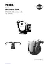
NEPTUN
ZATURN
JUPITER
Original
Instruction book
67030102-110 - version 1.10
GB - 05.2016
www.hardi.es
www.hardi-international.com

The original instruction book is approved and published in English. All other languages are
translations of the original. In the event of any confl icts, inaccuracies or deviations between
the English original and other languages the English version shall prevail.
Since it is ILEMO-HARDI S.A.U. policy to continually improve our products, we reserve the right
to make changes in the design, accessories, specifi cations and maintenance instructions at
any time and without notice.
ILEMO-HARDI S.A.U. is exempt from any obligation as regards instruments purchased before
or after such changes. ILEMO-HARDI S.A.U. cannot undertake any responsibility for possible
omissions or inaccuracies in this publication, although it has done everything in its power to
make this information as complete and correct as possible.
As this instruction book covers models, specifi cations or equipment that are only available in
certain countries, please pay particular attention to the paragraphs dealing with your specifi c
model.
Published and printed by ILEMO-HARDI S.A.U.
Congratulations for choosing a HARDI crop protection product. The reliability and effi ciency
of this machine depend entirely on the care it receives. The fi rst step is to carefully read and
pay attention to this instruction book. It contains essential information on correctly using and
ensuring a long useful life of this quality product.
As this instruction book includes all versions of the equipment, including the entire diff erent
hydraulic boom and operating unit versions, please pay particular attention to the paragraphs
dealing with your specifi c model.
This book should be read in conjunction with the ‘Spraying Techniques’ booklet.

1
Table of Contents
1 - EC Declaration
EC Declaration of Conformity .............................................................................................................. 5
2 - Safety
Operator safety ................................................................................................................................... 7
Symbols .................................................................................................................................................................................................................................................................7
Precautions ..........................................................................................................................................................................................................................................................7
3 - Description
General information ............................................................................................................................ 9
Overview ..............................................................................................................................................................................................................................................................9
Use of the mist blower ..............................................................................................................................................................................................................................11
Roadworthiness ............................................................................................................................................................................................................................................ 11
Identifi cation plate ......................................................................................................................................................................................................................................11
Chassis .................................................................................................................................................................................................................................................................11
Tank .......................................................................................................................................................................................................................................................................12
Liquid system .................................................................................................................................... 13
General information ...................................................................................................................................................................................................................................13
The liquid circuit ...........................................................................................................................................................................................................................................13
Diaphragm pump ........................................................................................................................................................................................................................................13
Valves ...................................................................................................................................................................................................................................................................13
Valves and symbols .....................................................................................................................................................................................................................................13
Manifold system ............................................................................................................................................................................................................................................14
Blue valve – Blue disc = Return valve ..............................................................................................................................................................................................14
Circuit Diagram ..............................................................................................................................................................................................................................................15
Suction fi lter ....................................................................................................................................................................................................................................................15
Safety valve.......................................................................................................................................................................................................................................................16
Pressure manifold .........................................................................................................................................................................................................................................16
Suction and pressure pulsation dampers .....................................................................................................................................................................................16
Agitator ...............................................................................................................................................................................................................................................................16
Operating unit ................................................................................................................................................................................................................................................17
BK/2 ......................................................................................................................................................................................................................................................................17
MC/2 operating unit ................................................................................................................................................................................................................................... 17
BS/2 ......................................................................................................................................................................................................................................................................17
SV operating unit ..........................................................................................................................................................................................................................................17
SA operating unit .........................................................................................................................................................................................................................................17
CA operating unit .........................................................................................................................................................................................................................................17
CB operating unit .........................................................................................................................................................................................................................................17
Filters ....................................................................................................................................................................................................................................................................17
Powder mixer ..................................................................................................................................................................................................................................................17
TurboFiller ........................................................................................................................................................................................................................................................ 18
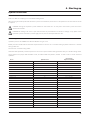
Axial blower units ............................................................................................................................. 19
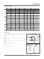
Technical information ................................................................................................................................................................................................................................19
EF820, EF920, AB750, AB820, AB920, AG820, AG920, IAG820, IAG920, SF65, SF85 and XF90 .......................................................................19
Air fl ow for axial air kits .............................................................................................................................................................................................................................21
Defl ectors ..........................................................................................................................................................................................................................................................22
Gearbox ..............................................................................................................................................................................................................................................................23
Fan .........................................................................................................................................................................................................................................................................23
Specifi c for SF and XF axial fans .........................................................................................................................................................................................................23
Centrifugal Blower Units (Turbines) .................................................................................................. 24
General information ...................................................................................................................................................................................................................................24
HF540 (TS3 P540 / TS6 P540 Single)...............................................................................................................................................................................................24
HF540D (TD3-P540 Double) ...............................................................................................................................................................................................................24
HF640D (TD3-P640 Double) ..............................................................................................................................................................................................................24
Protective grid ................................................................................................................................................................................................................................................25
Gearbox ..............................................................................................................................................................................................................................................................26
HF540, HF540D and HF 640D Turbines ..........................................................................................................................................................................................26
Clutch (All blower types) .........................................................................................................................................................................................................................26
Equipment ......................................................................................................................................... 27
Ring drawbar ...................................................................................................................................................................................................................................................27
Fork drawbar ................................................................................................................................................................................................................................................... 27
Turnable drawbar .........................................................................................................................................................................................................................................27

2
Table of Contents
Wedges ...............................................................................................................................................................................................................................................................28
Light kit ...............................................................................................................................................................................................................................................................28
Booms..................................................................................................................................................................................................................................................................28
The LINER boom .........................................................................................................................................................................................................................................28
The ATLAS boom ..........................................................................................................................................................................................................................................29
The BOXER boom .........................................................................................................................................................................................................................................30
The CRONOS boom ....................................................................................................................................................................................................................................31
Break away clutch ........................................................................................................................................................................................................................................32
Particularly for CRONOS boom ............................................................................................................................................................................................................32
Pneumatic spray system ..........................................................................................................................................................................................................................33
Hydropneumatic spray system ............................................................................................................................................................................................................33
IRIS system, continuation of Hydro pneumatic system ......................................................................................................................................................34
4 - Starting up
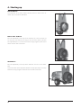
General information .......................................................................................................................... 35
Unloading the mistblower from the truck ...................................................................................................................................................................................35
Before starting up for the fi rst time ...................................................................................................................................................................................................35
Counterweights ............................................................................................................................................................................................................................................35
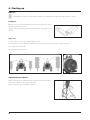
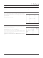
Mechanical connections .................................................................................................................... 36
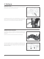
Adjusting the drawbar length ..............................................................................................................................................................................................................36
Jockey wheel ...................................................................................................................................................................................................................................................36
Connecting the fork drawbar ...............................................................................................................................................................................................................36
Connecting the ring drawbar ...............................................................................................................................................................................................................36
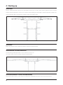
Connecting the articulated drawbars .............................................................................................................................................................................................37
Lock device on turnable drawbar ......................................................................................................................................................................................................37
Coupling the driveshaft............................................................................................................................................................................................................................38
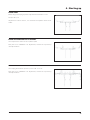
Hydraulic connections ....................................................................................................................... 39
General information ...................................................................................................................................................................................................................................39
Tractor requirements ..................................................................................................................................................................................................................................39
Electrical connections ....................................................................................................................... 40
General information ...................................................................................................................................................................................................................................40
Operating unit ................................................................................................................................................................................................................................................40
Rate controller................................................................................................................................... 41
Rate controller DB 3610 ............................................................................................................................................................................................................................41
Rate controller DB 3620 ............................................................................................................................................................................................................................42
Fluid circuit ....................................................................................................................................... 43
Suction fi lter ....................................................................................................................................................................................................................................................43
Pressure damper ...........................................................................................................................................................................................................................................43
Diaphragm pump ........................................................................................................................................................................................................................................43
Defl ectors ..........................................................................................................................................................................................................................................................44
Booms ............................................................................................................................................... 47
General information ...................................................................................................................................................................................................................................47
FIX ..........................................................................................................................................................................................................................................................................47
START ................................................................................................................................................................................................................................................................... 47
ATLAS START .................................................................................................................................................................................................................................................... 48
ATLAS AGILE .....................................................................................................................................................................................................................................................48
ATLAS SOLID FIX and ATLAS SOLID FIX GV..................................................................................................................................................................................48
ATLAS SOLID CONVERT and ATLAS SOLID GV CONVERT ..................................................................................................................................................... 48
BOXER START ...................................................................................................................................................................................................................................................49
BOXER SOLID VERTICAL FIX or CONVERT .....................................................................................................................................................................................49
BOXER SOLID HORIZONTAL ................................................................................................................................................................................................................... 49
Adjustment of BOXER boom .................................................................................................................................................................................................................50
CRONOS BOOM .............................................................................................................................................................................................................................................50
SOLID ...................................................................................................................................................................................................................................................................50
RIDER ....................................................................................................................................................................................................................................................................51
VARIA .................................................................................................................................................................................................................................................................... 51
CRONOS GV ....................................................................................................................................................................................................................................................51
General for all boom models ................................................................................................................................................................................................................ 52
Break away clutch .......................................................................................................................................................................................................................................52
Adjustment of hydraulic fold ................................................................................................................................................................................................................ 52
Transport bracket ........................................................................................................................................................................................................................................53
Adjustment of upright .............................................................................................................................................................................................................................53

3
Table of Contents
Adjustment of out spray device ..........................................................................................................................................................................................................53
The hydraulic version .................................................................................................................................................................................................................................54
Adjustment of inner 4 spray device ..................................................................................................................................................................................................54
Hydraulic adjustment of the Convert brackets ........................................................................................................................................................................55
IRIS system setup ..........................................................................................................................................................................................................................................55
Cannons .............................................................................................................................................................................................................................................................56
Calibration.........................................................................................................................................................................................................................................................56
5 - Operation
Blower unit ........................................................................................................................................ 57
Safety information .......................................................................................................................................................................................................................................57
Selecting the gear ........................................................................................................................................................................................................................................57
While moving the Sprayer ......................................................................................................................................................................................................................58
Adjusting the fan A6820 and SF65/SF85 and XF90 ................................................................................................................................................................59
Single side blinds (Optional) .................................................................................................................................................................................................................59
Fluid circuit ....................................................................................................................................... 60
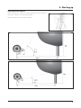
Filling/washing location requirements ...........................................................................................................................................................................................60
Filling with water ..........................................................................................................................................................................................................................................60
Filling through tank lid ..............................................................................................................................................................................................................................61
Filling the rinsing tank ...............................................................................................................................................................................................................................61
Rinsing nozzle .................................................................................................................................................................................................................................................61
Filling the clean water tank ....................................................................................................................................................................................................................62
Drain valve ........................................................................................................................................................................................................................................................62
Manifold system ............................................................................................................................................................................................................................................62
Filling liquid chemicals by HARDI TurboFiller (optional) ...................................................................................................................................................... 63
TurboFiller rinsing.........................................................................................................................................................................................................................................64
Power supply...................................................................................................................................................................................................................................................65
Installation of control unit brackets ..................................................................................................................................................................................................65
Adjusting the BK/2 Operating Unit ...................................................................................................................................................................................................66
MC/2 operating unit ................................................................................................................................................................................................................................... 66
BS2 operating unit ......................................................................................................................................................................................................................................67
SV operating unit ..........................................................................................................................................................................................................................................67
CA operating unit .........................................................................................................................................................................................................................................68
The SA Operating unit, is either 2, 4 or more section ............................................................................................................................................................ 68
CB operating unit .........................................................................................................................................................................................................................................68
CB operating unit with bypass valve ................................................................................................................................................................................................69
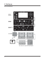
Control boxes ..................................................................................................................................................................................................................................................69
FB 3605 ...............................................................................................................................................................................................................................................................69
FB 3610 ...............................................................................................................................................................................................................................................................69
FB 3620 ...............................................................................................................................................................................................................................................................69
HB 3610 ..............................................................................................................................................................................................................................................................70
The Joystick S selector .............................................................................................................................................................................................................................70
HB 3620 ..............................................................................................................................................................................................................................................................71
Cannon L-M-T .................................................................................................................................................................................................................................................71
Hydraulic control of the CANNON ...................................................................................................................................................................................................71
The hydraulic adjustment ......................................................................................................................................................................................................................72
Vegetation sensor is optionally equipped ....................................................................................................................................................................................72
Rate controller DB3610 ..........................................................................................................................................................................................................................73
Rate controller DB3620 ..........................................................................................................................................................................................................................74
Extended joystick .........................................................................................................................................................................................................................................75
Example of speed and pressure limit settings ...........................................................................................................................................................................75
Cleaning ............................................................................................................................................ 76
General information ...................................................................................................................................................................................................................................76
Cleaning and maintaining the fi lters ...............................................................................................................................................................................................76
Cleaning the tank and liquid system ...............................................................................................................................................................................................77
Use of rinsing tank and rinsing nozzles (optional) ...................................................................................................................................................................77
6 - Maintenance
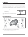
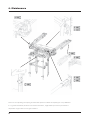
Lubrication ........................................................................................................................................ 80
General information ...................................................................................................................................................................................................................................80
Lubricating and greasing the mistblower ....................................................................................................................................................................................80
Suitable lubricants .......................................................................................................................................................................................................................................81

4
Table of Contents
Transmission shaft .......................................................................................................................................................................................................................................83
Tank transmission shaft ...........................................................................................................................................................................................................................83
Diaphragm pump ........................................................................................................................................................................................................................................83
Filters and fi ttings .........................................................................................................................................................................................................................................84
Fork drawbar ................................................................................................................................................................................................................................................... 84
Ring drawbar ...................................................................................................................................................................................................................................................84
Articulated drawbar ....................................................................................................................................................................................................................................85
Axles with brake ............................................................................................................................................................................................................................................85
Service and maintenance intervals ................................................................................................... 86
General information ...................................................................................................................................................................................................................................86
Every 10 working hours – Spray circuit ..........................................................................................................................................................................................86
Every 10 working hours – Suction fi lter .........................................................................................................................................................................................86
Every 10 hours of operation – Pressure fi lters ............................................................................................................................................................................87
Every 10 working hours – Nozzles .....................................................................................................................................................................................................87
Every 50 working hours – Transmission shaft, chassis, air pressure and diaphragm pump .........................................................................88
Every 100 working hours – Drawbar ................................................................................................................................................................................................ 88
Every 250 working hours – Wheels, brakes, hoses and gearbox .................................................................................................................................... 88
Every 1000 working hours – Full service ........................................................................................................................................................................................88
Every 1000 working hours - Gearbox oil change ..................................................................................................................................................................... 88
Every 1000 working hours - Fan clutch inspection .................................................................................................................................................................89
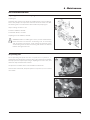
Annual maintenance of tank PTO .....................................................................................................................................................................................................90
Occasional maintenance ................................................................................................................... 91
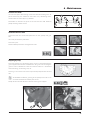
Replacing the 321 valves and diaphragms ..................................................................................................................................................................................91
SV operating unit ..........................................................................................................................................................................................................................................91
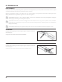
CB Section valve ............................................................................................................................................................................................................................................92
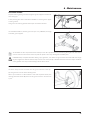
Cleaning the air kit .....................................................................................................................................................................................................................................94
Tank level indicator adjustment ..........................................................................................................................................................................................................95
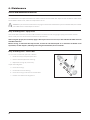
Replacing the valves and 364 and 464 diaphragms ..............................................................................................................................................................95
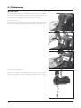
Grease Gun Calibration .............................................................................................................................................................................................................................96
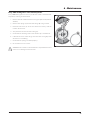
Greasing the Pump .....................................................................................................................................................................................................................................96
Service and Maintenance Intervals ................................................................................................... 97
50 Hours Service - Greasing the Pump ........................................................................................................................................................................................... 97
Occasional Maintenance ................................................................................................................... 98
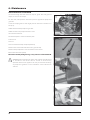
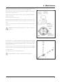
Lifting and Removing the Pump ........................................................................................................................................................................................................98
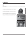
Pump Valves and Diaphragms Renewal ........................................................................................................................................................................................98
Adjusting the 3-way valve ...................................................................................................................................................................................................................100
Replacing the driveshaft protector guard ................................................................................................................................................................................. 100
Replacing the driveshaft crossheads ............................................................................................................................................................................................ 100
Replacing the seal on the drain valve...........................................................................................................................................................................................101
Storing the mistblower at the end of the season ................................................................................................................................................................. 101
Preparing the machine for use after storage ........................................................................................................................................................................... 102
7 - Troubleshooting
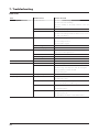
Operational problems ..................................................................................................................... 103
General information ................................................................................................................................................................................................................................ 103
Fluid circuit .................................................................................................................................................................................................................................................... 104
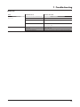
Blower unit .................................................................................................................................................................................................................................................... 105
Electrical problems ......................................................................................................................... 106
Emergency function – Fluid circuit ................................................................................................................................................................................................ 106
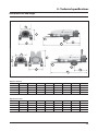
8 - Technical specifi cations
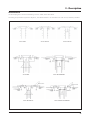
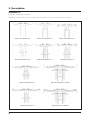
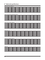
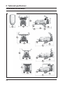
Axial dimensions and weight .......................................................................................................... 107
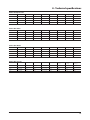
Turbines dimensions and weight .................................................................................................... 110
Conversion factors (SI to Imperial) .................................................................................................................................................................................................. 112
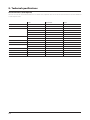
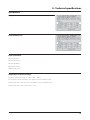
Specifi cations .................................................................................................................................. 113
Pump model 363/7 .................................................................................................................................................................................................................................. 113
Pump model 321/10 ............................................................................................................................................................................................................................... 113
Filters and nozzles ..................................................................................................................................................................................................................................... 113
Temperature and pressure range .................................................................................................................................................................................................... 113
Materials and recycling ................................................................................................................... 114
Disposing of the mistblower .............................................................................................................................................................................................................. 114
Index

5
1 - EC Declaration
EC Declaration of Conformity
Manufacturer: ILEMO HARDI S.A.U.
Polígono Industrial El Segre, 712, 713
25191 Lleida
SPAIN
Declares the following product(s):
NEPTUN
ZATURN
JUPITER
- were manufactured in conformity with the applicable provisions of the Directive 2006/42/EC on machinery, and
- all the applicable provisions of the Council Directive 2004/108/EC (EMC)
Lleida, March 2015
Josep Maria Godia
Technical Director
ILEMO HARDI S.A.U.

6

7
Operator safety
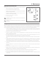
Symbols
These symbols are used in the book and require special attention. The meaning of the four symbols is:
This symbol means DANGER. Be alert as your safety is involved!
This symbol means WARNING. Be alert as your safety may be involved!
This symbol means ATTENTION. This will guide you on how to correctly and safely use the sprayer equipment.
This symbol means NOTE.
Precautions
Please note these precautions and safe operating practices before using the sprayer.
General information
Read and fully understand this instruction book before using the equipment. It is also equally important that other
operators of the equipment read and understand this book.
If you do not fully understand any part of this instruction book after reading it, please contact your HARDI distributor
for further information before using the equipment.
Local law may demand the operator to be certifi ed to use this spray equipment. Comply with the law.
The tractor seat is the safest area when handling the equipment.
Wear protective clothing. Protective clothing may vary according to the chemical product being used. Comply with regulations.
Wash and change clothes after spraying. Clean the tools if they have become contaminated.
Do not eat, drink or smoke while spraying or working with contaminated equipment.
In the event of poisoning, immediately seek medical advice. Remember to identify the chemicals used.
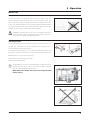
Filling and spraying
Be careful not to hit persons or objects while manoeuvring the spraying equipment, especially when reversing.
Slow down when driving over uneven terrain as the machine could overturn.
Keep children away from the sprayer.
Do not attempt to enter the tank.
Do not climb over the sprayer unless it has been securely fastened. The boom is only secure when it is placed in the
transport brackets.
2 - Safety

8
2 - Safety
Service
Always pressure test with clean water before fi lling with chemicals. Do not remove the hose if the machine is turned
on.
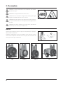
DANGER! Do not exceed the maximum recommended r.p.m.
Rinse and wash out the equipment after use and before servicing.
Do not remove the hose if the machine is turned on. Always replace all safety devices or shields immediately after
servicing.
Disconnect the power supply before servicing, and de-pressurise the equipment after use and servicing.
If an arc welder is used on the equipment, disconnect any power leads before welding.
Remove all infl ammable or explosive materials from the area.
The External Cleaning Device should not be used if any part of the equipment has been damaged, including safety
devices, high-pressure hoses, etc.

9
3 - Description
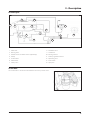
General information
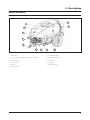
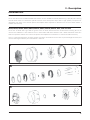
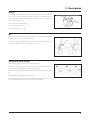
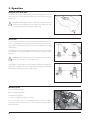
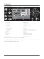
Overview
1. Main tank
2. Level indicator, optionally on top of the tank
3. Manifold valves
4. Suction fi lter
5. Pump
6. Rinsing tank
7. Clean water tank
8. Main lid and strainer
9. TurboFiller
10. Drawbar
11. Operating unit
1
2
6
10
11
4
8
3
7
59

10
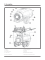
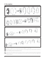
3 - Description
12. Chassis
13. Fan house
14. Grid and air guide
15. Centre cover
16. Bumper and light bar
17. Gear box fi lling point
18. Air outlet
19. Spray line
20. Adjustable bottom defl ector
21. Operating unit and hydraulic valves
12
16
14
18
13
17
15
19
20
13
12
21
17
16

11
3 - Description
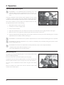
Use of the mist blower
The HARDI mist blower is designed for applying chemical products used for crop protection. This equipment may only be
used for this purpose. The use of this equipment for other purposes is not allowed. If there is no special law in your region
which obliges the user to have a permit, it is recommended to be well-prepared for protecting crops in a correct way and
for handling chemical products safely so as to avoid unnecessary risks to people and the environment while spraying takes
place.
For environmental issues the air kit is off ered with option to close either left or right side of the air stream from the blower.
These blinds, are mandatory in some sensitive areas, to avoid chemical contaminated air, blowing towards river sides and
water channels
Roadworthiness
When driving on public roads and other places where the road safety code or where there are other special rules and
regulations for marking and lights on machinery, the machine must be equipped to comply with these regulations.
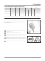
ATTENTION! For models not fi tted with brakes the maximum speed is 25 km/h and 40 km/h for those with. This
could vary according to local legislation. Contact your local authorities to fi nd out the current maximum speed
limits.
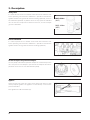
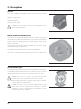
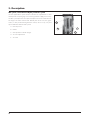
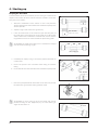
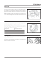
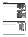
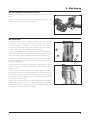
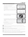
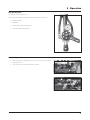
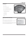
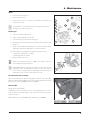
Identifi cation plate
The identifi cation plate is located on the front right-hand side of the
machine and is riveted to the chassis. It indicates the make, model, serial
number, and date of manufacture.
The serial number is also engraved onto the chassis. The number is
found above the identifi cation plate, as indicated in the picture. The
serial number consist of fi ve digits.
Chassis
The monoblock cold-pressed metal chassis is highly durable and built to last under everyday use under extreme conditions.
It is manufactured using only the most advanced laser cutting and automated soldering processes. To protect against
corrosion it is coated with a polyurethane bi-component paint on top of a highly adherent, steel blasted base.

12
3 - Description
Tank
The main tank made of impact-proof, UV-resistant and chemical resistant polyethylene has a purposeful design with no
sharp corners for easy cleaning. Nominal contents are 1000, 1500, 2000 or 3000 l. A large, easy to read tank contents
indicator is placed on the front - right-hand side and another one is placed on the left side. First one is visible from the
tractor cabin. The fi lling hole is accessible from the left-hand side. This ensures an easy access for the fi lling of spray liquid,
cleaning of the tank, etc. The mistblower is equipped with a clean water tank integrated with the main tank design.

13
3 - Description
Liquid system
General information
All the suction system functions are operated via a 3-way valve. The pressure valve is also to be found in the pressure circuit.
The low pressure circuit is called HLC (Hardi Liquid Circuit).
The liquid circuit
Consist of manifold system in the working zone (front part) where pressure manifold receives liquid from the pump, and
distributes to the diff erent options on the sprayer – to the operating unit, to the TurboFiller, to the bottle cleaner, to the
Powder mixer in strainer etc., all according to confi guration of options. The suction manifold in same area allows suction
from main tank, rinsing tank or external water source, if fi tted, depending on its confi guration.
The pressure side of the liquid circuit is fi tted with a safety valve to protect the circuit against misuse of excessive pressure.
See chapter “Safety valve”
Diaphragm pump
Pumps with a diaphragm: Models 321/10 (max. 20 bar) or 363/7 (max. 20 bar)
They are low pressure and robustly built. Use only grease for lubrication. The 363 model has six diaphragms and the 321
has two. This type of pump is self-priming, works without oil and can run dry as long as necessary.
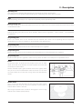
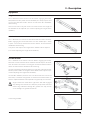
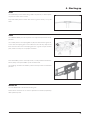
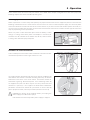
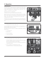
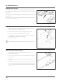
Valves
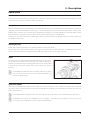
The suction valve is located above the pump and is used to select where
to suck liquid from. Either suction from the main tank for spraying or
from the rinse tank for internal cleaning of the liquid circuit. The function
is selected by turning the handle of the valve towards the desired
function.
ATTENTION! If one of the handles is too tight - or too loose (=liquid
loss) - the valve needs to be serviced. For more information, see
section on “Maintenance”.
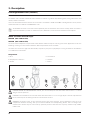
Valves and symbols
The valves are identifi ed by coloured discs fi tted on the valves themselves. The symbols correspond to the optional
accessories, and are located on the discs for quick identifi cation and handling. To activate/open a function, turn the lever
to the desired function.
ATTENTION: Only the functions to be used should be activated – the other valves should always be kept closed.
ATTENTION: If the handle of a MANIFOLD valve is too tight – or too loose (loss of fl uid)– the valve needs to be
serviced. For more information, see the section on ‘Maintenance’.

14
3 - Description
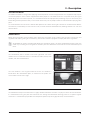
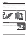
Manifold system
The functions of the spray circuit are operated via the centrally situated
MANIFOLD with colour coded plates and pictorial symbols for easy
operation.
The modular valve system facilitates the addition of optional extras on
both pressure (A) and suction (B) for agitation and for rinsing nozzle
(optional equipment).
Blue valve – Blue disc = Return valve
Towards agitation Towards the suction pump
The position of the return MANIFOLD valve determines where the excess
fl ow from the fl uid circuit goes. When the arrow on the handle points
to a symbol, the excess fl uid will be fully sent towards that function (the
example shows agitation). This valve does not have the ‘0’ position.
A
B

15
3 - Description
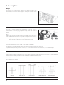
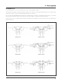
Circuit Diagram
1. Main tank
2. Rinsing tank
3. Powder mixer or bottle cleaner (optionally)
4. Pump
5. Suction fi lter
6. Manometer
7. Safety valve
8. Manifold valves
9. TurboFiller
10. Rinsing nozzles
11. Ventury agitation nozzles
12. Operating unit
13. Inline fi lters
14. Spray line
Suction fi lter
The suction fi lter is located underneath the three-way suction valve.
1
2
6
3
513 14
8
7
412
11
10
9

16
3 - Description
Safety valve
It is made of cast iron and is situated at the front of the machine next
to the operating unit. From this manifold it is possible to activate the
agitator and the rinsing nozzle for internal cleaning (optional), as well as
the Turbofi ller (optional) or powder mixer. Do only open the manifold
valve in order to send pressure to the desired device, as in the example
given: the Turbofi ller.
Pressure manifold
It is made of plastic and is situated on the front of the machine next
to the operating unit. From this manifold it is possible to activate the
agitator and the rinsing nozzle for internal cleaning (optional).
Suction and pressure pulsation dampers
The 321 pump is fi tted with a pulsation damper on suction and pressure
sides. The pressure side damper is pressurized. The dampers will reduce
pulsations and secure an even fl ow from the pump.
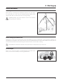
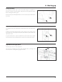
Agitator
At the front and on each side of the inside of the tank there are two
ventury-shaped agitators. The agitators are activated by a valve on the
pressure manifold.
Each agitator has a Ø 3mm nozzle (D).
D
MAX. 20 bar
(HLC)
MAX. 40 bar
(HPC)

17
3 - Description
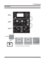
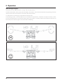
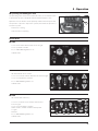
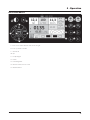
Operating unit
Your sprayer will be equipped with operating unit accordingly to country specifi cations.
The mistblower can be equipped with following types of operating units: MC/2, CB/2, SV and CB.
BK/2
Manual operating unit with pressure equalisation. Optionally remote operated by cable
MC/2 operating unit
It has two section valves which control RH and LH sides. The section valves are remote controlled from the tractor cab by
via two bowden cables.
BS/2
Manual operating unit, placed near drivers position. Allows pressure regulation, section controls , and manometer
incorporated.
SV operating unit
It has 2 or 4 section valves. It uses solenoid valves for on/off of each section. The SV operating unit has no pressure
equalization device. Pressure regulation is done manually in the working zone.
SA operating unit
Remote operated solenoid sections valves with manual pressure regulation
CA operating unit
Remote operated solenoid sections with pressure equalisation device and manual pressure regulation
CB operating unit
Electrical remote pressure regulation, section valves by means of motor valves with pressure equalization device.
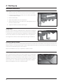
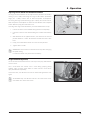
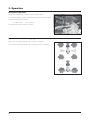
Filters
The pressure fi lters are located on the bumper next to the air outlet
nozzle. In the HLC circuit the fi lters are made of plastic and in the HPC
circuit they are made of brass.
All fi lters should be kept in good condition and cleaned regularly. Make
sure you to use correct combinations of fi lter and mesh size. The mesh
size should always be less than the average of the total fl ow from the
nozzles.
Powder mixer
This is used to rinse the fi lter basket in tank’s fi lling hole when adding
powdered products that do not dissolve properly or form lumps in
contact with the water in the tank.
After using the powder mixer it must be disengaged as it uses a large
amount of the available pump capacity..

18
3 - Description
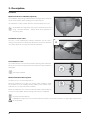
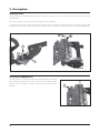
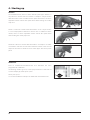
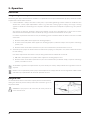
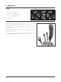
TurboFiller
Chemical inductor, TurboFiller (optional)
The TurboFiller allows fi lling of both powder and liquid spray chemicals
safe and conveniently when standing next to the machine.
The Turbofi ller is neatly stowed under the main tank when not in use..
ATTENTION! Local legislation may require chemicals to be fi lled
using a chemical inductor - Always follow local legislation in
force at any time.
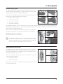
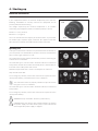
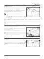
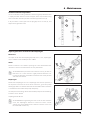
TurboFiller suction valve
The valve is used simultaneously with the TurboFiller. The valve has 2
settings: In the position A, indicated on the picture, it is closed. Open the
valve when chemicals are to be fi lled into the TurboFiller.
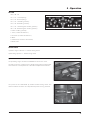
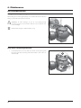
Turbo Defl ector valve
This Turbo Defl ector valve activates the Vortex fl ushing of the TurboFiller.
Lift the lever to lock it in open position for continuous liquid rotation in
the hopper.
Start Turbo Defl ector
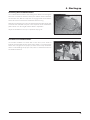
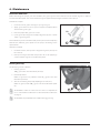
Chemical Container Rinsing lever
The upper lever is used for two purposes:
When the TurboFiller lid is open: For rinsing empty containers. Place
the container over the rotating fl ushing nozzle in the middle of the
TurboFiller to rinse the inside of the container.
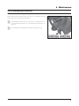
When the TurboFiller lid is closed: Use the Chemical Container Rinsing
lever to rinse the hopper when the fi lling of chemicals is completed.
Chemical Container Rinsing
DANGER! Do not press the lever unless the multi-hole nozzle is covered by a container as spray liquid may otherwise
hit the operator.
A
Page is loading ...
Page is loading ...
Page is loading ...
Page is loading ...
Page is loading ...
Page is loading ...
Page is loading ...
Page is loading ...
Page is loading ...
Page is loading ...
Page is loading ...
Page is loading ...
Page is loading ...
Page is loading ...
Page is loading ...
Page is loading ...
Page is loading ...
Page is loading ...
Page is loading ...
Page is loading ...
Page is loading ...
Page is loading ...
Page is loading ...
Page is loading ...
Page is loading ...
Page is loading ...
Page is loading ...
Page is loading ...
Page is loading ...
Page is loading ...
Page is loading ...
Page is loading ...
Page is loading ...
Page is loading ...
Page is loading ...
Page is loading ...
Page is loading ...
Page is loading ...
Page is loading ...
Page is loading ...
Page is loading ...
Page is loading ...
Page is loading ...
Page is loading ...
Page is loading ...
Page is loading ...
Page is loading ...
Page is loading ...
Page is loading ...
Page is loading ...
Page is loading ...
Page is loading ...
Page is loading ...
Page is loading ...
Page is loading ...
Page is loading ...
Page is loading ...
Page is loading ...
Page is loading ...
Page is loading ...
Page is loading ...
Page is loading ...
Page is loading ...
Page is loading ...
Page is loading ...
Page is loading ...
Page is loading ...
Page is loading ...
Page is loading ...
Page is loading ...
Page is loading ...
Page is loading ...
Page is loading ...
Page is loading ...
Page is loading ...
Page is loading ...
Page is loading ...
Page is loading ...
Page is loading ...
Page is loading ...
Page is loading ...
Page is loading ...
Page is loading ...
Page is loading ...
Page is loading ...
Page is loading ...
Page is loading ...
Page is loading ...
Page is loading ...
Page is loading ...
Page is loading ...
Page is loading ...
Page is loading ...
Page is loading ...
Page is loading ...
Page is loading ...
Page is loading ...
Page is loading ...
Page is loading ...
-
 1
1
-
 2
2
-
 3
3
-
 4
4
-
 5
5
-
 6
6
-
 7
7
-
 8
8
-
 9
9
-
 10
10
-
 11
11
-
 12
12
-
 13
13
-
 14
14
-
 15
15
-
 16
16
-
 17
17
-
 18
18
-
 19
19
-
 20
20
-
 21
21
-
 22
22
-
 23
23
-
 24
24
-
 25
25
-
 26
26
-
 27
27
-
 28
28
-
 29
29
-
 30
30
-
 31
31
-
 32
32
-
 33
33
-
 34
34
-
 35
35
-
 36
36
-
 37
37
-
 38
38
-
 39
39
-
 40
40
-
 41
41
-
 42
42
-
 43
43
-
 44
44
-
 45
45
-
 46
46
-
 47
47
-
 48
48
-
 49
49
-
 50
50
-
 51
51
-
 52
52
-
 53
53
-
 54
54
-
 55
55
-
 56
56
-
 57
57
-
 58
58
-
 59
59
-
 60
60
-
 61
61
-
 62
62
-
 63
63
-
 64
64
-
 65
65
-
 66
66
-
 67
67
-
 68
68
-
 69
69
-
 70
70
-
 71
71
-
 72
72
-
 73
73
-
 74
74
-
 75
75
-
 76
76
-
 77
77
-
 78
78
-
 79
79
-
 80
80
-
 81
81
-
 82
82
-
 83
83
-
 84
84
-
 85
85
-
 86
86
-
 87
87
-
 88
88
-
 89
89
-
 90
90
-
 91
91
-
 92
92
-
 93
93
-
 94
94
-
 95
95
-
 96
96
-
 97
97
-
 98
98
-
 99
99
-
 100
100
-
 101
101
-
 102
102
-
 103
103
-
 104
104
-
 105
105
-
 106
106
-
 107
107
-
 108
108
-
 109
109
-
 110
110
-
 111
111
-
 112
112
-
 113
113
-
 114
114
-
 115
115
-
 116
116
-
 117
117
-
 118
118
-
 119
119


Hardi NEPTUN EF820 Instruction book
- Type
- Instruction book
- This manual is also suitable for
Ask a question and I''ll find the answer in the document
Finding information in a document is now easier with AI
Related papers
-
 Hardi ZEBRA CANNON Instruction book
-
 Hardi COMMANDER 7000 Instruction book
-
 Hardi ATV Series User manual
-
 Hardi Eagle Boom User manual
-
 Hardi ZATURN Instruction book
-
 Hardi ES 30 User manual
-
 Hardi HC 2500 Series Instruction book
-
 Hardi Ranger 550 Instruction book
-
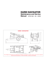 Hardi Navigator Series Maintenance And Service Manual
-
 Hardi MEGA 230 User manual


Other documents
-
Poolmaster 27402 Operating instructions
-
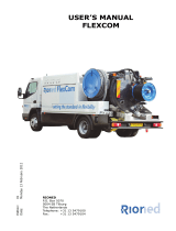 Rioned Flexcom User manual
-
 Cleveland AM180 User manual
-
GCE MediVital E Operating instructions
-
Graco 3A5131M, Husky™ 2150e Electric-Operated Diaphragm Pump Owner's manual
-
Parkside 16 L Backpack Pressure Sprayer User manual
-
Makita GMP01 User manual
-
GGM Gastro FMSA10 Owner's manual
-
-
NORTHSTAR High Flow ATV Broadcast and Spot Sprayer Owner's manual

