Page is loading ...

0070-10-0691 Accutorr Plus™ Service Manual
Accutorr Plus
™
is a U.S. trademark of Mindray DS USA, Inc.
Masimo SET
®
and LNOP
®
are registered trademarks of Masimo Corporation.
Nellcor
®
, OxiMax
®
, Oxiband
®
, and Durasensor
®
are U.S. registered trademarks of Nellcor Puritan Bennett Inc.
Oxisensor
™
is a trademark of Nellcor Puritan Bennett Inc.
Velcro
®
is a registered trademark of Velcro Industries B.V.
Copyright © Mindray DS USA, Inc., 2008. All rights reserved. Contents of this publication may not be reproduced in any
f
orm without permission of Mindray DS USA, Inc.

Accutorr Plus Service Manual 0070-10-0691 iii
Table of Contents
Contents..................................................................................................................................................... vii
Foreword ................................................................................................................................................... vii
Notes and Precautions ............................................................................................................................... viii
Notes.......................................................................................................................................................... ix
Precautions ................................................................................................................................................ x
Theory of Operation...................................................................................................................................... 1 - 1
Major Functional Blocks of the Accutorr Plus......................................................................................... 1 - 2
CPU/NIBP Module Assembly with LCD Display................................................................................... 1 - 3
Software Overview ........................................................................................................................... 1 - 3
CPU Hardware Controls ................................................................................................................... 1 - 4
NIBP Hardware functions................................................................................................................. 1 - 4
Main pressure transducer circuitry ........................................................................................... 1 -4
Over pressure transducer circuitry ............................................................................................ 1-4
Five A/D channels .................................................................................................................... 1 - 5
Pulse Channel Filter .................................................................................................................. 1 - 5
Inflation Pump .......................................................................................................................... 1 - 5
Bleed Valve ............................................................................................................................... 1 - 5
Dump Valve .............................................................................................................................. 1 - 5
Cuff Inflation Requirements ..................................................................................................... 1 - 5
Pulse Acquisition Requirements ............................................................................................... 1 -6
Artifact Rejection Requirements .............................................................................................. 1 -6
Parameter determination Requirements .................................................................................... 1 - 6
Major Hardware Components........................................................................................................... 1 - 6
CPU ........................................................................................................................................... 1 - 6
Flash Memory ........................................................................................................................... 1 - 6
Battery Backed Up Static RAM ................................................................................................ 1 - 6
Nonvolatile RAM ..................................................................................................................... 1 - 6
Micromanager ........................................................................................................................... 1 - 7
Battery Backup Voltage Regulator Circuitry ............................................................................ 1 - 7
Real Time Clock ....................................................................................................................... 1 - 7
Recorder Interface ..................................................................................................................... 1 - 7
Communication Block .............................................................................................................. 1 - 8
Backlight LED Driver ............................................................................................................... 1 - 8
LCD Trend Display .............................................................................................................
..... 1 - 8
Temperature Interface ............................................................................................................... 1 - 9
SpO
2
Interface ........................................................................................................................... 1 - 9
SpO
2
Processor Circuit Boards ................................................................................................................ 1 - 11
SpO
2
General Theory Of Operation.................................................................................................. 1 -11
Nellcor
®
Nell-3 SpO
2
Circuit Board Theory of Operation .............................................................. 1 - 11
Nellcor
®
Nell-3 Interface Board Theory of Operation ..................................................................... 1 - 12
Masimo SET
®
Technology............................................................................................................... 1 - 12
Masimo
®
Interface Board Theory of Operation ............................................................................... 1 - 12
Main Power Supply.................................................................................................................................. 1 - 14
Description ........................................................................................................................................ 1 - 14
Power Supply Output Voltages......................................................................................................... 1 - 14
Lithium Ion Battery and Charger ...................................................................................................... 1 - 14
LED and Tone Module............................................................................................................................. 1 - 16

Table of Contents
iv 0070-10-0691 Accutorr Plus Service Manual
Keypad Control ................................................................................................................................. 1 - 17
Specifications.................................................................................................................................................. 2 - 1
Performance Specifications...................................................................................................................... 2 - 1
NIBP Measurement Cycle Time ....................................................................................................... 2 - 1
Pulse Rate ................................................................................................................................. 2 - 2
Maximum Cuff Pressure ................................................................................................................... 2 - 2
Inflation Source................................................................................................................................. 2 - 2
Leak Rate .......................................................................................................................................... 2 - 2
Cuff Vent Rate .................................................................................................................................. 2 - 2
Temperature (Predictive) .................................................................................................................. 2 - 2
Nellcor
®
SpO
2
.................................................................................................................................. 2 - 3
Masimo
®
SpO
2
................................................................................................................................. 2 - 3
Battery............................................................................................................................................... 2 - 5
Real-Time Clock ............................................................................................................................... 2 - 5
Safety Characteristics............................................................................................................................... 2 - 6
Risk (Leakage) Currents ................................................................................................................... 2 - 6
Dielectric Withstand ......................................................................................................................... 2 - 6
Ground Resistance ............................................................................................................................ 2 - 6
Type of Protection Against Electric Shock.......................................................................................2-6
Degree of Protection Against Electric Shock ................................................................................... 2 -6
Physical Characteristics............................................................................................................................ 2 - 7
Environmental Characteristics ................................................................................................................. 2 - 7
Electrical Ratings ..................................................................................................................................... 2 - 8
Agency Compliance ................................................................................................................................. 2 - 8
Electromagnetic Compatibility ................................................................................................................ 2 - 9
Repair Information ....................................................................................................................................... 3 - 1
Introduction .............................................................................................................................................. 3 - 1
Safety Precautions .................................................................................................................................... 3 - 2
General Troubleshooting Guidelines ....................................................................................................... 3 - 3
Troubleshooting Tips ........................................................................................................................ 3 - 3
Exchange Program ............................................................................................................................ 3 - 3
Test Equipment Required......................................................................................................................... 3 - 4
Troubleshooting (Problem Isolation) ....................................................................................................... 3 - 5
Error Codes ............................................................................................................................... 3 - 5
Isolating the Problem, System Level ................................................................................................ 3 - 6
Isolating the Problem within the Main Unit......................................................................................3-7
Isolating the Problems with Optional Accessory Modules............................................................... 3 - 7
Clinical Issues with AccuTemp IR Ear Thermometer Applications................................................. 3 - 7
Multiple Temperature Measurements ....................................................................................... 3 - 7
How the AccuTemp IR Measures Arterial Temperature (Adults/Pediatrics) ........................... 3 - 8
Troubleshooting ........................................................................................................................ 3 - 9
Maintenance .............................................................................................................................. 3 - 9
Disassembly Instructions.......................................................................................................................... 3 - 10
Removal of the Rear Housing........................................................................................................... 3 - 10
Removal of the Front Bezel .............................................................................................................. 3 - 10
Removal of the Keyboard Assembly ................................................................................................3-10
Removal of the LED/Tone board...................................................................................................... 3 - 10

Accutorr Plus Service Manual 0070-10-0691 v
Table of Contents
Removal of the CPU / NIBP board................................................................................................... 3 - 11
Removal of the Power Supply Assembly ......................................................................................... 3 - 12
Removal of the LCD Display (Advanced Model) ............................................................................ 3 - 13
Removal and replacement of the Internal Li-Ion Battery ................................................................. 3 - 13
Removal of the AC Input Receptacle Assembly .............................................................................. 3 - 13
Thermal Printer (optional module) ................................................................................................... 3 - 13
Thermometer, Predictive (optional module)..................................................................................... 3 -13
AccuTemp IR, Infrared Thermometer (optional module) ................................................................ 3 - 14
AccuTemp IR Mounting Cradle ....................................................................................................... 3 - 14
Interconnect Cables Run List ................................................................................................................... 3 - 15
Interface Specifications, Connectors and Functions. ........................................................................ 3 - 15
Connector to LED / Tone PCB, J-2 .......................................................................................... 3 - 15
Power Supply Header, J-502 .................................................................................................... 3-17
J-2 Keypad Connector .............................................................................................................. 3 - 17
J-4 Speaker Connector .............................................................................................................. 3 - 18
Recorder Connector, J-5 ........................................................................................................... 3 - 18
Thermometer Connector, J-4 .................................................................................................... 3-19
SpO
2
Connector, J-7 ................................................................................................................. 3 - 19
NIBP Pump Connector, J-505 .................................................................................................. 3 - 20
LED Backlight Connector, J-651 .............................................................................................. 3 - 20
Communication Connector, J-603 ............................................................................................ 3 - 20
LCD Connector, J-8 .................................................................................................................. 3 - 20
Power Supply Connectors................................................................................................................. 3 - 21
AC input connector, J-2 ............................................................................................................ 3 - 21
DC output connector, J-3 .......................................................................................................... 3 - 21
Battery connector, J-4 ............................................................................................................... 3 - 22
Replacement Parts and Isometric Drawings............................................................................................... 4 - 1
Introduction .............................................................................................................................................. 4 - 1
Available Replacement Parts And Sub-Assemblies................................................................................. 4-1
Product Variations And Options .............................................................................................................. 4 - 1
Exchange Program ................................................................................................................................... 4 - 2
Replacement Parts Pricing Information ................................................................................................... 4 - 2
Ordering Information ............................................................................................................................... 4 - 2
Isometric Drawings and Parts Lists.......................................................................................................... 4 - 3
Accessory Modules and Mounting Parts Lists......................................................................................... 4 - 10
Recorder Module Replacement Parts List ........................................................................................ 4 -10
Predictive Temperature Module Replacement Parts List ................................................................. 4 - 10
Universal Rolling Stand (P/N ACCTROLLSTD, Assembly Parts List) .......................................... 4 - 11
Mounting Options ............................................................................................................................. 4 - 12
Calibration ..................................................................................................................................................... 5 - 1
Introduction .............................................................................................................................................. 5 - 2
Status and Error Code Table ............................................................................................................. 5 - 2
Error Codes ............................................................................................................................... 5 - 2
Precautions And Guidelines ..................................................................................................................... 5 - 4
Test Equipment And Special Tools Required.......................................................................................... 5 - 4
Power-up Sequence, Internal Testing....................................................................................................... 5 - 4
Service Diagnostics .................................................................................................................................. 5 - 5

Table of Contents
vi 0070-10-0691 Accutorr Plus Service Manual
Introduction (Hidden Key)................................................................................................................ 5 - 5
Software Version Test (0a, 0b) ......................................................................................................... 5 - 6
Keypad Test ...................................................................................................................................... 5 - 7
LED Test (2a, 2b).............................................................................................................................. 5 - 8
Communication Test (3a, 3b)............................................................................................................ 5 - 8
Recorder Test (4) .............................................................................................................................. 5 - 8
Pump Test (5).................................................................................................................................... 5 - 9
Bleed Rate Test (6a, 6b) ........................................................................................................... 5 - 9
Leak Test (7) ..................................................................................................................................... 5 - 10
Over Pressure Test (8a, 8b, 8c) ......................................................................................................... 5 - 10
Pulse Channel DC Offset Test (9a, 9b, 9c) .......................................................................................5-11
Pulse Channel Average Noise Test (10a, 10b, 10c).......................................................................... 5 - 11
Main Pressure Transducer Verification Test (11a, 11b, 11c) ........................................................... 5 - 11
Verification of Accutorr Plus Pneumatic Performance using an NIBP Simulator (11d).................. 5 - 12
Overpressure Transducer Verification <12c, 12a, 12b> ................................................................... 5 - 13
Main Pressure Transducer Calibration.............................................................................................. 5 - 14
Overpressure Transducer Calibration ............................................................................................... 5 - 15
Predictive Thermometer Verification And Calibration............................................................................ 5-16
Water Bath Method........................................................................................................................... 5 - 16
Temperature Verification Test, Infrared Thermometer (Applicable Only To Units Equipped With A
Temperature Option) ................................................................................................................... 5 - 16
Low Battery Sensing......................................................................................................................... 5 - 17
Setting the Current Time.......................................................................................................................... 5 - 18
NIBP Normal Operation........................................................................................................................... 5 - 19
Trend Memory Initialization .................................................................................................................... 5 - 19
SpO
2
Normal Operation (Accutorr Plus model with SpO
2
) .................................................................... 5 - 20
Preventive Maintenance................................................................................................................................ 6 - 1
Introduction .............................................................................................................................................. 6 - 1
Limitations Of Physiological Simulators ................................................................................................. 6 - 1
Preventive Maintenance Schedule ........................................................................................................... 6 - 2
Mechanical and Physical Visual Inspection (One Year Interval) ..................................................... 6 - 2
Electrical Safety and Performance Checks (One Year Interval)....................................................... 6 - 2

Accutorr Plus Service Manual 0070-10-0691 vii
Contents Introduction
Contents
1.0 Theory of Operation ........................................................................ 1-1
2.0 Specifications .................................................................................. 2-1
3.0 Repair Information ........................................................................... 3-1
4.0 Replacement Parts and Isometric Drawings ................................. 4-1
5.0 Calibration ........................................................................................ 5-1
6.0 Preventive Maintenance .................................................................. 6-1
On the first page of each chapter a table of contents for that chapter is provided.
This is a Service Manual for the Accutorr Plus monitor. There are no Operating
Instructions in this manual. Complete operating instructions and listing of available
accessories are published in the Accutorr Plus Operating Instructions—
P/N 0070-00-0692-02 (English) and P/N 0070-00-0695 (international languages).
Foreword
This Service Manual (P/N 0070-00-0691) is intended as a guide, for technically qualified
personnel, to use during repair and calibration procedures for the Accutorr Plus (part
number 0998-00-0444-9XX).
Use this Accutorr Plus Service Manual ONLY for the monitor part numbers listed
below. This manual provides specific information that may not be applicable to other
part numbers.
The part number (P/N) and serial number are necessary for positive identification of the
correct parts. They are located on the rear panel label of the Accutorr Plus unit.
MONITOR PART NUMBER (P/N) MONITOR CONFIGURATION
0998-00-0444-91A Basic (NIBP only) (IEC, English)
0998-00-0444-91G Basic (NIBP only) (IEC, German)
0998-00-0444-91P Basic (NIBP only) (IEC, Spanish)
0998-00-0444-91F Basic (NIBP only) (IEC, French)
0998-00-0444-91T Basic (NIBP only) (IEC, Italian)
0998-00-0444-93A
Advanced (Nellcor
®
) (IEC, English)
0998-00-0444-93G
Advanced (Nellcor
®
) (IEC, German)
0998-00-0444-93P
Advanced (Nellcor
®
) (IEC, Spanish)
0998-00-0444-93F
Advanced (Nellcor
®
) (IEC, French)
0998-00-0444-93T
Advanced (Nellcor
®
) (IEC, Italian)
0998-00-0444-94A
Advanced (Masimo
®
) (IEC, English)
0998-00-0444-94G
Advanced (Masimo
®
) (IEC, German)
0998-00-0444-94P
Advanced (Masimo
®
) (IEC, Spanish)

Introduction Notes and Precautions
viii 0070-10-0691 Accutorr Plus Service Manual
Notes and Precautions
NOTES are a general information statement concerning the Accutorr Plus.
A CAUTION is provided to alert the user to use special care necessary for the safe and
effective use of the device. They may include actions to be taken to avoid effects on
patients or users that may not be potentially life threatening or result in serious injury, but
about which the user should be aware. Cautions are also provided to alert the user to
adverse effects on this device of use or misuse and the care necessary to avoid such
effects.
Please read and adhere to all notes and precautions listed here and in the appropriate areas
throughout this manual.
0998-00-0444-94F
Advanced (Masimo
®
) (IEC, French)
0998-00-0444-94T
Advanced (Masimo
®
) (IEC, Italian)
MONITOR PART NUMBER (P/N) MONITOR CONFIGURATION

Accutorr Plus Service Manual 0070-10-0691 ix
Notes Introduction
Notes
NOTE: See the serial and product number label on the
rear panel of the unit for part number
identification. This manual also includes
information on the optional Recorder and
Predictive Temperature modules and Infrared
Temperature module.
NOTE: This manual does not provide operating
instructions. Consult the Operating Instructions
Manual for proper operation of this monitor.
NOTE: Unauthorized servicing may void the remainder of
the warranty. Check with the factory or with a
local authorized representative to determine the
warranty status of a particular instrument.
NOTE: Do not change Room Number and /or Bed Letter
on the Accutorr Plus during the transmission of
temperature data.
NOTE: The AccuTemp IR thermometer should be at room
temperature when it is used. If it has been in a
very warm or very cold environment it may need
time for the thermometer temperature to equalize
to ambient temperature.
NOTE: Special care should be taken to insure that the
front panel and glare screen are not scratched.
NOTE: New batteries are shipped in a discharged state
for safety reasons. A new battery must be
charged for 4 hours for Li-Ion before first use. The
monitor may be used with AC mains power during
the charge cycle but battery operation could be
limited during this time.
NOTE: Mindray DS USA, Inc. maintains a policy of
continuous development for product improvement
and reserves the right to change materials,
specifications, and prices without notice.
NOTE: When replacing a Keyboard, you must replace the
Graphic Panel.
NOTE: Monitors with Nellcor
®
and Masimo
®
SpO
2
do not
report SpO
2
Runtime and Boot Software Versions.
NOTE: The Accutorr Plus always displays time in a 24
hour format.

Introduction Precautions
x 0070-10-0691 Accutorr Plus Service Manual
Precautions
CAUTION: Li-lon batteries used in this device may present a
risk of fire or chemical burn if mistreated. Do not
disassemble, heat above 100°C (212°F), or
incinerate. Replace battery with P/N: 0146-00-
0069 only. Use of another battery may present a
risk of fire or explosion.
CAUTION: Dispose of used battery properly. Keep away from
children. Do not disassemble and do not dispose
of in fire.
CAUTION: Soldering and solder removal equipment must be
low voltage operated and grounded to avoid
static charge and stray current induced
component damage. Maximum wattage: 25 W.
CAUTION: The Inside Of This Instrument Contains Static
Sensitive Components. Use correct static
protection safeguards.
This publication may have been updated to reflect product design changes and/or manual
improvements. This manual is correct to the best of our knowledge at the time of
publication and reflects the product variations shown in this manual. You may contact
Technical Support to confirm that the manual is applicable for your unit. Updated manuals
are available for sale.

Accutorr Plus Service Manual 0070-10-0691 1 - 1
1.0
Theory of Operation
1.1 Major Functional Blocks of the Accutorr Plus .............................. 1-2
1.2 CPU/NIBP Module Assembly with LCD Display ............................ 1-3
1.3 SpO2 Processor Circuit Boards ..................................................... 1-11
1.4 Main Power Supply .......................................................................... 1-14
1.5 LED and Tone Module ..................................................................... 1-16
This section of the manual explains the basic architecture of the Accutorr Plus. It is an
overview, not a detailed circuit analysis. It is intended to be a tool, that if used properly,
will lead to an understanding of the functions executed by a major functional block, and
thus enabling a logical isolation and resolution of malfunctions.
The Accutorr Plus is offered in many functional configurations, including the options
licensed and manufactured by third parties. The third party circuits will be treated solely
as “black box” devices, with only the relevant input, output and power sources described.
The Theory of Operation section describes only the highest configuration level. Units built
with fewer or different options may not use all of the capabilities of the Accutorr Plus, yet
the over-all theories will remain constant.

Major Functional Blocks of the Accutorr Plus Theory of Operation
1 - 2 0070-10-0691 Accutorr Plus Service Manual
1.1 Major Functional Blocks of the Accutorr Plus
• CPU/NIBP Module Assembly with LCD Display
• Interface and SpO
2
Processor Board
• Main Power Supply and Battery Charger Assembly
• LED/Tone Module Assembly

Accutorr Plus Service Manual 0070-10-0691 1 - 3
Theory of Operation CPU/NIBP Module Assembly with LCD Display
1.2 CPU/NIBP Module Assembly with LCD Display
The Accutorr Plus CPU/NIBP module controls the functions of the NIBP, temperature
probes, and SpO
2
module; transmits output data to the recorder; and provides a serial I/O
port connection for PC communication.
The CPU/NIBP module distributes power from the power supply, which includes power
and control signals to the LED/Tone module, to the remaining components of the system
such as the recorder and SpO
2
modules. The CPU/NIBP module also supplies separate
power to the LED backlight and provides trend data to the display.
The CPU/NIBP circuit board is comprised of both software and hardware. The following
is a summary of the software control exercised and the major hardware affected. This is
for informational purposes only, and both software and hardware controls may be changed
at any time without notice.
1.2.1 Software Overview
The software performs the following functions:
1. Initializes hardware and software modules
• Microcontroller ports and communication (serial) interfaces
• Software entry points and variables
• Read configuration from NVRAM
2. Performs power up diagnostic
• Microcontroller, FLASH, and STATIC RAM test
3. Performs NIBP functions
• Start measurement
• Repeat measurement
• Over pressure limit
• Enter or exit test mode
• Abort measurement
• Enter or exit calibration mode
• Update alarm limits
• Report alarm status
•Report data
• Determine inflation pressure
• Perform controlled cuff deflation
• Monitor DC and AC pressure and acquire pulsations
• Reject artifacts
• Decide on termination point and exhaust cuff pressure
• Smooth pulsation data
• Determine systolic, mean, diastolic pressure and heart rate
• Check alarm conditions

CPU/NIBP Module Assembly with LCD Display Theory of Operation
1 - 4 0070-10-0691 Accutorr Plus Service Manual
4. Transmits/Receives data to/from Infrared/Predictive Temperature modules
5. Manages Recorder functions
6. Manages Keypad interface
7. Provides RS232 communication to PC for software download
8. Supports Service Diagnostics
9. Supports Nurse Call feature
10. Checks error conditions
• Maintain watchdog timer
• Run-time diagnostic
11. Transmits/Receives data to/from SpO
2
module, if present
12. Controls LCD view angle
1.2.2 CPU Hardware Controls
1. Microcontroller executes the above software functions, including:
•NIBP
• Recorder
• Temperature module, PTM or IR
•SpO
2
•LCD
2. Battery Back Up Circuitry for Power Savings
• Static memory
• Non-volatile RAM for configuration and future serial number
3. Flash ROM for Program Storage and Execution
4. Static RAM for Data Storage
5. RS232 level translation for PC Download and second interface for CIS/HIS
6. Real time clock with 16K of Lithium backed up NV RAM
1.2.3 NIBP Hardware functions
1.2.3.1 Main pressure transducer circuitry
A pressure transducer and amplifier combination is provided to acquire the cuff pressure
signal.
1.2.3.2 Over pressure transducer circuitry
An over pressure transducer, independent of the main pressure transducer. Over pressure
limits are set according to the patient size.

Accutorr Plus Service Manual 0070-10-0691 1 - 5
Theory of Operation CPU/NIBP Module Assembly with LCD Display
1.2.3.3 Five A/D channels
All channels are at 12-bit resolution and digitized at 101 Hz:
1. DC pressure
2. AC pressure (pulse)
3. Hardware over pressure transducer
4. Hardware over pressure cooperator reference
5. Battery voltage monitoring, when the Accutorr is in battery operation
1.2.3.4 Pulse Channel Filter
A high-pass filter is provided to isolate the pulsatile component from the DC cuff
pressure. This pulsatile component is digitized as the pulse channel. The gain of this AC
coupled channel is programmable in a manner consistent with the specified range of pulse
amplitudes.
1.2.3.5 Inflation Pump
A pump capable of inflating the cuff within the specified time limit.
1.2.3.6 Bleed Valve
A valve and control system capable of bleeding down the cuff pressure.
1.2.3.7 Dump Valve
A valve to rapidly discharge the residual cuff pressure at the end of the measurement
cycle.
1.2.3.8 Cuff Inflation Requirements
The cuff is initially inflated to a software-determined pressure dependent upon patient
size. In timer mode, it should be a predetermined increment, traditionally 50 mmHg (40
mmHg for Neonates) (determined by the CPU), above the previous systolic reading, after
the first measurement. The software detects error conditions in the pneumatic system such
as disconnected cuffs or kinked hoses. To reduce the possibility of over inflating the cuff,
the pump may be driven at a lower speed when pressurizing small neonatal cuffs. This is
achieved by pulse width modulating the pump control signal. Further control of the
neonatal inflation rate may be achieved by using the bleed valve to relieve some portion of
the pump's delivery.

CPU/NIBP Module Assembly with LCD Display Theory of Operation
1 - 6 0070-10-0691 Accutorr Plus Service Manual
1.2.3.9 Pulse Acquisition Requirements
Pulse amplitudes from 0.06 mmHg to 12 mmHg are recognized. Pulse rates can range
from 30 bpm to 250 bpm. The software discriminates pulses from the digitized pulse
channel signal, and characterizes the pulses for amplitude, DC pressure, and pulse period.
False triggering, due to the dicrotic notch or noise, is minimized.
1.2.3.10 Artifact Rejection Requirements
The software provides means of artifact rejection, both during acquisition and during
subsequent processing of the pulse array. Means of rejecting artifacts include attention to
the timing and amplitude of pulses relative to adjacent pulses. If motion artifact is detected
during acquisition, the software may cause temporary suspension of the bleed down
process until a quiescent patient condition returns.
1.2.3.11 Parameter determination Requirements
Pulses that are deemed acceptable after artifact processing are entered in the pulse array.
Heart rate is taken to be the average rate of the pulse array data. Pulse periods differing
excessively from the median are ignored. Pulses that do not appear to fit the amplitude
envelope are removed. The systolic, diastolic, and mean pressures are then calculated in
accordance with standard algorithms. A fair amount of data manipulation and computation
is required in the parameter determination. The results are reported no more than one
second from the termination of the pulse acquisition phase.
1.2.4 Major Hardware Components
1.2.4.1 CPU
A microcontroller (min. 16MHz) with three (3) serial communication controllers (SCC), a
serial communication port (SCP), programmable chip select lines (to minimize glue
logic), a IDMA controller, and parallel I/O ports for discrete signals.
1.2.4.2 Flash Memory
512K x 16 Flash ROM used for program storage and execution. A Flash ROM is used also
for downloading new revisions of software via the CPU's serial I/O lines (SCC).
1.2.4.3 Battery Backed Up Static RAM
512K x 16 static ram is used for data storage, trend information, etc. This memory is used
for data storage. Therefore, a battery back up is provided.
1.2.4.4 Nonvolatile RAM
Nonvolatile ram is used for configuration and serial number information. This memory
requires a battery back up.

Accutorr Plus Service Manual 0070-10-0691 1 - 7
Theory of Operation CPU/NIBP Module Assembly with LCD Display
1.2.4.5 Micromanager
This device provides a number of features that are useful for management of this board.
They are listed as follows:
A. ON/STANDBY capability through keyboard control
B. Watchdog timer
C. Conversion of CMOS SRAM to pseudo nonvolatile memory
1.2.4.6 Battery Backup Voltage Regulator Circuitry
Implements regulation of the STANDBY VOLTAGE from the main power supply to 4V
+/- 0.2V dc with a current draw of 821 uA max.
1.2.4.7 Real Time Clock
This device provide seconds, minutes, hours, date of the month, month, and year with leap
year compensation. The device is memory mapped to be pointed to as software requires.
Also, provisions for running this device include main power supply and battery operation
in order for the RTC to keep time when the system is not powered. A lithium battery is
included, having a minimum of 10 years of operation, for configuration and clock data
retention during battery changes and main battery failure. Accuracy is +/- 1 minute/week.
1.2.4.8 Recorder Interface
IDMA capability for writing 8-bit buffered parallel data to the recorder. Handshaking
signals to specify new line to be printed, request for next byte of data.

CPU/NIBP Module Assembly with LCD Display Theory of Operation
1 - 8 0070-10-0691 Accutorr Plus Service Manual
1.2.4.9 Communication Block
The module provides the following interfaces and functions:
• RS-232E drive from TTL levels. RS-232E driver for CIS/HIS that will provide
minimum of 9V signal level.
• IC based DC/DC converter capable of converting VCC to 12VDC, with leakage
current when off < 100uA. High frequency operation to limit emitted fields. Capable of
providing an output current of 125 mA @ 12Vdc, with an efficiency of 80% or higher.
• Signal driver for an external isolated relay that will be used for Nurse Call, provided on
pins of the 9-pin RS-232 connector.
The RS-232E interface required is implemented using a Maxim, MAX236 Multi-Channel
Transceiver (U602). This chip was chosen because it has a minimum ±9 volt output signal
level. Communication is to support a 5 wire interface, 4 signals and a ground. The signals
are described below:
All RS-232 signals are ESD protected by a U603, an SM14M24C Transient Voltage
Suppressor array. The +12 VT dc power required by the Nurse Call cable is supplied from
the onboard DC/DC converter. The MAX236 receivers are controlled by logic signal
CSTAT*. Logic 0 enables the receivers; otherwise, they are tri-stated.
The RS-232 signals appear on connector J603, a dual row 14 pin header which will have a
mating 14 pin pendant ribbon cable attached. The other end of the ribbon cable assembly
is a 9 pin panel mount ‘D’ connector.
1.2.4.10 Backlight LED Driver
The LED driver module is implemented with Linear LT3474, step-down 1A LED driver. It
can source constant current maximum up to 1A. The current can be programmed by
setting the voltage at Vadj pin (pin 13) through resistors R42 and R14. The switching
frequency is programmed to 300KHz for best duty cycle (i.e, 96%) for higher efficiency.
The typical LED drop voltage of 3.5V is achieved by programming the constant output
LED current of 71mA. The Vadj is sourced from external voltage source (i.e., +5V VCC)
by external resistor divider.
1.2.4.11 LCD Trend Display
DAC control provided from the LED/Tone Board controls the LCD View Angle.
SIGNAL DESCRIPTION INPUT/OUTPUT
RXD Received Data from DCE to
DTE device
Input
TXD Transmitted Data from DTE
to DCE device
Output
RTS Request to send from DTE
to DCE device
Output
CTS Clear to Send from DCE
device
Input
GND Signal Ground Input

Accutorr Plus Service Manual 0070-10-0691 1 - 9
Theory of Operation CPU/NIBP Module Assembly with LCD Display
1.2.4.12 Temperature Interface
The board provides a Serial Interface to either Temperature module.
1.2.4.13 SpO
2
Interface
The board provides a Serial Interface to SPO
2
and reset control of the module.
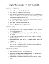
FIGURE 1-1 CPU Block Diagram

CPU/NIBP Module Assembly with LCD Display Theory of Operation
1 - 10 0070-10-0691 Accutorr Plus Service Manual
FIGURE 1-2 NIBP Block Diagram

Accutorr Plus Service Manual 0070-10-0691 1 - 11
Theory of Operation SpO
2
Processor Circuit Boards
1.3 SpO
2
Processor Circuit Boards
The Accutorr Plus can be equipped with one of two optional technologies:
•Nellcor
®
SpO
2
system
•Masimo
®
SpO
2
system
Each technology uses proprietary sensors and interface cables. There are no “adapters”
possible or available.
1.3.1 SpO
2
General Theory Of Operation
Regardless of manufacturer, SpO
2
determination is based on the relative attenuation of a
red and an infrared light source. A sensor from the instrument contains two sets of LEDs
to illuminate a portion of the body (for example, a fingertip) and a single photo sensor
detects the light returned. The LEDs are alternately pulsed, red and infrared. Since
hemoglobin is the carrier of oxygen in the blood and the relative attenuation of the light
sources is proportional to the amount of oxygen carried by the hemoglobin, a relative level
of saturated hemoglobin can be determined. Since we are measuring the ratio of red and
infrared return from the circulatory system, the detection method is substantially
independent of skin color or total skin attenuation. Since the blood flow has a pulsatile
characteristic, a pulse rate can also be computed from this information.
NOTE: There is no calibration possible for the
determination of the SpO
2
% or of the pulse rate
derived. As mentioned above, we are measuring a
ratio of intensity of two light sources to
determine the % of saturated hemoglobin. The
determination is based on proprietary software
interpretation of the reflected light ratios, and it
is validated against strict clinical trials where
fresh arterial blood is examined with a clinical
blood gas analyzer. Once the software is
finalized, the SpO
2
monitor accuracy is fixed and
there are no possible adjustments.
NOTE: The wavelengths of the light emitted are
nominally 660nm and 890nm with the energy not
exceeding 15mV.
1.3.2 Nellcor
®
Nell-3 SpO
2
Circuit Board Theory of Operation
The Nell-3 is a complete SpO
2
detection and determination circuit, proprietary of
Nellcor
®
Puritan Bennett. Patient data is processed for serial transmission to the host
system.
/