Page is loading ...

INTRODUCTION
Chapters
1. Operation
2. Theory of Operation
3. Specifications
4. Repair Information
5. Schematics
6. Parts
7. Calibration
8. Preventive Maintenance
A complete, detailed table of contents begins on page iii. Also, on the first page of each
chapter a table of contents for that chapter is provided.
FOREWORD
This Service Manual (P/N 0070-00-0429) is intended as a guide, for technically qualified
personnel, to use during repair and calibration procedures for the Accutorr Plus (part
number 0998-00-0444-XX). NOTE: See the serial number label on the rear panel of the
unit for part number identification. This manual also includes information on the Recorder
and Predictive Temperature Modules.
The information in this manual has been divided into the eight chapters listed above.
This publication may have been updated to reflect product design changes and/or manual
improvements. Any such changes to this manual would be accomplished by supplying
replacement pages and instructions for inserting or affixing them into the manual.
NOTE
Unauthorized servicing may void the remainder of the warranty. Check with the
factory or with a local authorized Datascope representative to determine the
warranty status of a particular instrument.
NOTE: This product is year 2000 compliant.
Copyright © Datascope Corp., 1999. Printed in U.S.A. All rights reserved. Contents of this
publication may not be reproduced in any form without permission of Datascope Corp.
Accutorr Plus, Service Manual i
Chapter 1 - Operation
VAULT COPY
Rev AB.1 is available in Vault-PM on Voyager

This page intentionally left blank.
ii Accutorr Plus, Service Manual
Chapter 1 - Operation

INTRODUCTION .......................................i
1.0 OPERATION .......................................1-1
1.1 Introduction.........................................1-1
1.2 Controls and Indicators.................................1-3
1.2.1 Front Panel..................................1-4
1.2.2 Rear Panel ..................................1-13
1.2.3 Predictive Thermometer Module .................1-14
1.2.4 Recorder Module .............................1-15
1.3 Operation...........................................1-17
1.3.1 Setting-Up / Turning Power On ..................1-17
1.3.2 Patient Setup and Room/Bed Assignment...........1-18
1.3.2.1 Selecting the Patient Size .......................1-18
1.3.2.2 Cuff Inflation Pressure .........................1-18
1.3.2.3 Room Number and Bed Letter ...................1-19
1.3.3 Manual NIBP Measurements and General NIBP
Measurement Information.......................1-20
1.3.3.1 NIBP Pressure Limit Fail Safe....................1-22
1.3.3.2 Cuff Inflation Time............................1-22
1.3.3.3 Automatic Adjustment of Cuff Inflation Pressure
(Adaptive Inflation) ...........................1-22
1.3.4 Automatic NIBP Measurements (Interval Mode) .....1-23
1.3.4.1 Canceling an Automatic NIBP Measurement ........1-23
1.3.4.2 Changing the Interval setting ....................1-24
1.3.4.3 Effects of Changing the Room Number and /or Bed
Letter on the Interval Setting ....................1-24
1.3.4.4 Start and Deflate Functions......................1-24
1.3.5 Alarms .....................................1-25
1.3.5.1 Setting Alarm Limits ..........................1-25
1.3.5.2 Alarm Violations .............................1-26
1.3.5.3 How to Mute Alarms ..........................1-27
1.3.5.4 Alarms and Changing the Room Number and/or
Bed Letter...................................1-27
1.3.6 To View and Delete Stored Data (Trend Mode).......1-28
1.3.6.1 To View the Stored Measurements on the Accutorr
Plus NIBP ..................................1-28
1.3.6.2 To View the Stored Measurements on the Accutorr
Plus NIBP with Trend Screen and the Accutorr Plus
NIBP with Trend Screen and SpO
2
................1-29
Accutorr Plus Service Manual iii
Introduction
TABLE OF CONTENTS

1.3.6.3 To Delete the Stored Measurements on all
Models of the Accutorr Plus .....................1-29
1.3.7 Setting the Alarm Volume and Beep Volume ........1-30
1.3.8 Setting the LCD Contrast (View Angle Adjustment) . . 1-31
1.3.9 Display Time Out Mode........................1-32
1.3.10 SpO
2
Measurements (Accutorr Plus model with SpO
2
) . 1-33
1.3.10.1 Datascope Pulse Oximetry Sensors ................1-33
1.3.10.2 Sequence for Establishing SpO
2
with Nellcor
®
Pulse
Oximetry* ..................................1-37
1.3.10.3 Sequence for Establishing SpO
2
with Masimo
Ò
Pulse
Oximetry* ..................................1-40
1.3.11 Temperature Measurement (optional) ..............1-43
1.3.11.1 Predictive Thermometer Measurements ............1-43
1.3.11.2 How to Apply Probe Cover (PTM) ................1-43
1.3.11.3 How to Take Oral, Rectal, and Axillary Temperatures . 1-44
1.3.11.4 Storing Temperature Measurements ...............1-45
1.3.12 Recorder (optional) ............................1-46
1.3.13 How to Set the Clock (Date and Time) .............1-47
1.3.14 Battery Operation .............................1-48
1.3.15 User Configuration ............................1-49
1.3.16 Status and Error Codes .........................1-51
1.3.17 How to Attach Optional Thermometer and
Recorder Modules.............................1-52
1.3.18 Placement of the Quick Reference Card ............1-53
1.3.19 Placement of Recorder Paper Loading Label .........1-54
2.0 THEORY OF OPERATION ...........................2-1
2.1 Block Diagrams ......................................2-1
2.2 Detailed Circuit Descriptions ............................2-2
2.2.1 LED/CPU Module, 0670-00-0650-03, -04..........2-9
2.2.1.1 Hardware Overview ...........................2-9
2.2.1.2 Software Overview ............................2-9
2.2.1.3 Detailed Hardware Description...................2-10
2.2.2 NIBP Module, Linear Bleed .....................2-17
2.2.3 Recorder Module .............................2-20
2.2.4 Predictive Thermometer Module .................2-21
2.2.5 SpO
2
Module (Accutorr Plus with SpO
2
only) .......2-22
2.2.6 Main Power Supply............................2-25
2.2.7 Communication Board .........................2-26
2.2.8 LCD Inverter Module - 0670-00-0649 .............2-28
2.2.9 Nellcor
®
MP 304 SpO
2
Circuit Board
Theory of Operation ...........................2-29
2.2.10 Interface Nellcor
Ò
Board Theory of Operation .......2-30
iv Accutorr Plus Service Manual
Introduction
Revised 12/20/00

2.2.11 Masimo SET
Ò
Technology......................2-31
2.2.12 Masimo Interface Board Theory of Operation ........2-32
3.0 SPECIFICATIONS ..................................3-1
3.1. Performance Specifications ..............................3-1
3.2 Safety Characteristics ..................................3-6
3.3 Physical Characteristics ................................3-7
3.4 Environmental Characteristics ...........................3-7
3.5 Electrical Ratings .....................................3-7
3.6 Agency Compliance ...................................3-8
3.7 Electromagnetic Compatibility...........................3-8
4.0 REPAIR INFORMATION ............................4-1
4.1 Introduction.........................................4-1
4.2 Safety Precautions.....................................4-2
4.3 General Troubleshooting Guidelines ......................4-2
4.4 Test Equipment Required ..............................4-3
4.5 Troubleshooting (Problem Isolation) ......................4-4
4.5.1 Isolating the Problem, System Level ...............4-5
4.5.2 Isolating the Problem within the Main Unit.........4-5
4.5.3 Isolating the Problem with Optional Accessory Modules. . . 4-6
4.5.4 Clinical Issues................................4-6
4.6 Disassembly Instructions ...............................4-9
4.6.1 Removal of the Rear Housing (27) ................4-9
4.6.2 Removal of the Front Bezel (2) ...................4-9
4.6.3 Removal of the Keyboard Assembly (4).............4-9
4.6.4 Removal of the CPU Board Assembly (8) ...........4-10
4.6.5 Removal of the NIBP Circuit Assembly (30) ........4-10
4.6.6 Removal of the Power Supply Assembly (41) ........4-10
4.6.7 Removal of the Motor Filter and LCD
High Voltage Assembly (35) ....................4-11
4.6.8 Removal of the NIBP Air Pump Assembly (37) ......4-11
4.6.9 Removal of the LCD Display Assembly and Back Light (5) 4-11
4.6.10 Removal of the SpO
2
Circuit Board (40)............4-11
4.6.11 Removal and Replacement of the Internal Sealed
Lead Acid or Li-Ion Battery .....................4-12
4.6.12 Removal of the AC Input Receptacle Assembly (16) . . . 4-12
4.6.13 Thermal Printer (Optional Module) ...............4-12
4.6.14 Thermometer, Predictive (Optional Module) ........4-13
4.6.15 AccuTemp IR, Infrared Thermometer (optional
module) ....................................4-13
4.6.16 AccuTemp IR Mounting Cradle ..................4-13
Accutorr Plus Service Manual v
Introduction
Revised 12/20/00

4.6.17 Communication Board (45)......................4-13
5.0 ASSEMBLY AND SCHEMATIC DIAGRAMS ............5-1
6.0 REPLACEMENT PARTS .............................6-1
6.1 Introduction .........................................6-1
6.2 Available Replacement Parts and Sub-Assemblies ............6-1
6.3 Product Variations and Options ..........................6-1
6.4 Exchange Program ....................................6-1
6.5 Replacement Parts Pricing Information ....................6-2
6.6 Ordering Information..................................6-2
6.7 Abbreviations........................................6-3
6.8 Isometric Drawings and Parts List ........................6-5
6.8.1 Accutorr Plus Isometric Parts List (All Models) ......6-5
6.8.2 Recorder Module Isometric Parts List ..............6-13
6.8.3 Predictive Temperature Module Isometric Parts List. . . 6-15
6.8.4 Mobile Stand Type 1 (Gray Base) Assembly Parts List . 6-17
6.8.5 Mobile Stand Type 2 (Black Base) Assembly Parts List . 6-19
6.8.6 Mounting Options ............................6-19
6.9 Circuit Board Parts Lists................................6-21
7.0 CALIBRATION.....................................7-1
7.1 Introduction .........................................7-3
7.2 Warnings and Guidelines...............................7-3
7.3 Test Equipment and Special Tools Required.................7-3
7.4 Power-Up Sequence, Internal Testing......................7-4
7.5 Service Diagnostics....................................7-4
7.5.1 Introduction (Hidden Key) ......................7-4
7.5.2 Software Version Test (0a, 0b)....................7-5
7.5.3 Keypad Test .................................7-6
7.5.4 LED Test (2a, 2b) .............................7-7
7.5.5 Communications Test (3a, 3b) ...................7-7
7.5.6 Recorder Test (4) .............................7-7
7.5.6.1 Recorder Print Head Adjustment .................7-8
7.5.7 Pump Test (5)................................7-8
7.5.8 Leak Test (7).................................7-9
7.5.9 Over Pressure Test (8a, 8b, 8c) ...................7-9
7.5.10 Pulse Channel DC Offset Test (9a, 9b, 9c) ..........7-10
7.5.11 Pulse Channel Average Noise Test (10a, 10b, 10c) ....7-10
7.5.12 Main Pressure Transducer Verification Test
(11a, 11b, 11c) ...............................7-11
vi Accutorr Plus Service Manual
Introduction
Revised 9/20/07

7.5.13 Verification of Accutorr Plus Pneumatic Performance,
Using the “Cufflink” NIBP Emulator (11d) .........7-11
7.5.14 Over Pressure Transducer Verification (12c, 12a, 12b) . 7-12
7.5.15 Main Pressure Transducer Calibration..............7-12
7.5.16 Over Pressure Transducer Calibration ..............7-13
7.5.17 Battery Selection (13) ..........................7-13
7.6 Predictive Thermometer Verification and Calibration..........7-14
7.6.1 Temperature Accuracy Verification with the
Predictive Temperature Simulator ................7-14
7.6.2 Water Bath Method ...........................7-15
7.6.3 System Calibration Procedure ....................7-15
7.6.4 Temperature Verification Test, Infrared
Thermometer ................................7-16
7.6.5 Low Battery Sensing ...........................7-17
7.7 Battery Test for Accutorr Plus ...........................7-18
7.7.1 Low Battery Indicator and Low Battery Cut-Off ......7-18
7.7.2 Set the Current Time ..........................7-19
7.8 NIBP Normal Operation ...............................7-20
7.9 Trend Memory Initialization ............................7-21
7.10 SpO
2
Normal Operation (Accutorr Plus with SpO
2
only) .......7-21
8.0 PREVENTIVE MAINTENANCE .......................8-1
8.1 Introduction .........................................8-1
8.2 Limitations of Physiological Simulators ....................8-1
8.3 Preventive Maintenance Schedule .........................8-2
8.3.1 Mechanical and Physical Visual Inspection
(One Year Interval) ............................8-2
8.3.2 Electrical Safety and Performance Checks
(One Year Interval) ............................8-2
Accutorr Plus Service Manual vii
Introduction
Revised 09/20/07

This page intentionally left blank.
viii Accutorr Plus Service Manual
Introduction

CONTENTS OF THIS CHAPTER Page
1.1 Introduction.........................................1-1
1.2 Controls and Indicators ................................1-3
1.3 Operation...........................................1-17
1.1 INTRODUCTION
This section of the Service Manual (P/N 0070-00-0429) is provided as a review
of the Accutorr Plus NIBP, the Accutorr Plus NIBP with Trend Screen and the Accutorr
Plus NIBP with Trend Screen and SpO
2
functions and operation. The reader is
encouraged to refer to the Operating Instructions, P/N 0070-00-0428, for more
complete details.
Accutorr Plus, Service Manual 1-1
Chapter 1 - Operation
Revised 06/25/99
1.0 OPERATION

This page intentionally left blank.
1-2 Accutorr Plus, Service Manual
Chapter 1 - Operation

1.2 CONTROLS AND INDICATORS
This section of the Service Manual identifies and describes each control and display of the
Datascope Accutorr Plus NIBP, the Accutorr Plus NIBP with Trend Screen and the
Accutorr Plus NIBP with Trend Screen and SpO
2
. For step-by-step operating instructions
see Chapter 1.3, “Operation”.
The following is a list of all controls, connectors and indicators, their item number and
the page number. The item number refers to the call outs on the drawings within this
chapter. The page number refers to the page where the description of the item can be
found.
Accutorr Plus Service Manual 1-3
Chapter 1, Operation
CONTROL Page #
FRONT PANEL
1. NIBP Systolic Display 1-8
2. NIBP Diastolic Display 1-8
3. NIBP MAP Display 1-8
4. Pulse Rate Display 1-8
5. NIBP/SpO
2
Pulse Rate Indicator 1-8
6. SpO
2
Display 1-8
7. Liquid Crystal Display (LCD) 1-8
8. Menu Key 1-8
9. LCD Up Arrow Key 1-8
10. LCD Down Arrow Key 1-8
11. Select Key 1-9
12. Print Key 1-9
13. Print Indicator 1-9
14. Defaults Key 1-9
15. Datascope, Nellcor
®
or Masimo
SpO
2
Connector 1-9
16. AC Power Indicator 1-9
17. Battery Indicator 1-9
18. NIBP Connector 1-9
19. On/Standby Key 1-9
20. Memory Full Indicator 1-9
21. Delete Info. Key 1-10
22. Data Scan Key 1-10
23. Data Scan Indicator 1-10
24. Room/Bed Key 1-10
25. Bed Letter Display 1-10
26. Room Number Display 1-10
27. Patient Info. Down Arrow Key 1-10
28. Patient Info. Up Arrow Key 1-10
29. Set Alarms Key 1-11
CONTROL Page#
30. Mute Key 1-10
31. Mute Indicator 1-11
32. Timer/Temp Key 1-11
33. Interval/Elap. Time/Temp Display 1-11
34. Interval Key 1-11
35. Interval Indicator 1-11
36. Deflate Key 1-12
37. Patient Setup Key 1-12
38. Start NIBP Key 1-12
39. Start NIBP Indicator 1-12
40. Patient Size Indicators 1-12
41. Hidden Key 1-12
REAR PANEL
42. Thermometer Module Connector 1-13
43. Equipotential Lug 1-13
44. AC Power Connector 1-13
45. Communications Connector 1-13
46. Datascope Connector 1-13
47. Pole Mounting Handle and Cam 1-13
48. Recorder Module Connector 1-13
PREDICTIVE THERMOMETER MODULE
49. Probe Cover Holder 1-14
50. Probe Chamber 1-14
51. Probe Connector 1-14
RECORDER MODULE
52. Paper Door 1-15
53. Paper Tear Edge 1-15
Revised 02/15/00

1.2.1 Front Panel
1-4 Accutorr Plus Service Manual
Chapter 1, Operation
START
NIBP
TIMER/TEMP
+
-
HOLD TO CLEAR.
MEMORY FULL
PATIENT INFO.
ALARMS
INTERVAL TEMPELAP.TIME
ROOM BED
SYS.
MAP
NIBP
41
40
38
37
36
35
34
33
32
31
39
DEFLATE
INTERVAL
PATIENT
SETUP
MUTE
SET
ALARMS
BED
ROOM
DATA
SCAN
DELETE
INFO.
ON
STANDBY
DEFAULTS
PRINT
SELECTMENU
S/D/M
F/C
o
20/05
20/05
20/05
20/05
20/05
03:00
02:58
02:35
02:33
02:30
114/64
123/61
127/62
185/105
129/62
83
84
83
135
84
61
60
58
56
59
98.7
98.5
97.6
98.2
----
96
97
96
96
97
%SPO2
Sp0
2
NIBP
SpO
2
DIA.
30
29
28
27
26
25
24
23
22
21
20
19
181716151413121110
9
8
7
6
5
4
3
2
1
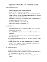
Figure 1-1 Front Panel - Accutorr Plus NIBP with Trend Screen and Datascope SpO
2

Accutorr Plus Service Manual 1-5
Chapter 1, Operation
Figure 1-2 Front Panel - Accutorr Plus NIBP with Trend Screen and Nellcor
®
or Masimo SpO
2
Revised 02/15/00
START
NIBP
TIMER/TEMP
+
-
HOLD TO CLEAR.
MEMORY F ULL
PATIENT INFO.
ALARMS
INTERVAL TEMPELAP.TIME
ROOM BED
SYS.
MAP
NIBP
41
40
38
37
36
35
34
33
32
31
39
DEFLATE
INTERVAL
PATIENT
SETUP
MUTE
SET
ALARMS
BED
ROOM
DATA
SCAN
DELETE
INFO.
ON
STANDBY
DEFAULTS
PRINT
SELECTMENU
S/D/M
F/C
o
20/05
20/05
20/05
20/05
20/05
03:00
02:58
02:35
02:33
02:30
114/64
123/61
127/62
185/105
129/62
83
84
83
135
84
61
60
58
56
59
98.7
98.5
97.6
98.2
----
96
97
96
96
97
%SPO2
Sp0
2
NIBP
SpO
2
DIA.
30
29
28
27
26
25
24
23
22
21
20
19
181716151413121110
9
8
7
6
5
4
3
2
1
Nellcor


1. NIBP Systolic Display
Displays the systolic blood pressure data from NIBP measurements. It is also used to
display NIBP error codes and systolic alarm limits.
2. NIBP Diastolic Display
Displays the diastolic blood pressure data from NIBP measurements. It is also used
to display diastolic alarm limits.
3. NIBP MAP Display
Displays the mean arterial pressure (MAP) information from NIBP measurements.
During a measurement, it will display the cuff pressure. It is also used to display the
MAP alarm limits and the inflation pressure when selecting the initial inflation
pressure.
4. Pulse Rate Display
Displays the pulse rate information from either the NIBP measurement or the SpO2
reading (Accutorr Plus model with SpO
2
). It is also used to display pulse rate alarm
limits.
5. NIBP/SpO
2
Pulse Rate Indicator
When the pulse rate displayed is based on an NIBP measurement, then NIBP is illu
-
minated. When the pulse rate displayed is based on an SpO
2
measurement
(Accutorr Plus model with SpO
2
), then SpO
2
is illuminated.
6. SpO
2
Display (Accutorr Plus model with SpO
2
)
Displays the %SpO
2
measurement information. This area is also used to display
the %SpO
2
alarm limits.
7. Liquid Crystal Display (LCD) (Accutorr Plus models with Trend Screen)
The Liquid Crystal Display (LCD) is used to display previous measurements (trend
list) for the selected patient, or a menu that controls the beep volume and alarm volume.
8. Menu Key (Accutorr Plus models with Trend Screen)
This key is used to toggle between the trend list screen and the menu screen in the
LCD. When the back light in the LCD is off, pressing this key turns it on. This key
is also used to adjust the LCD contrast. Press and hold the key for two beeps to enter
the adjustment mode. Use the Arrow keys (9 and 10) to change the contrast.
9. LCD Up Arrow Key (Accutorr Plus models with Trend Screen)
This key is used to scroll the trend data so that more recent measurements are
displayed in the LCD. When the back light in the LCD is off, pressing this key turns
it on. This key is also used to adjust the LCD contrast when in the adjustment mode.
Use the Menu key (8) to enter the adjustment mode.
10. LCD Down Arrow Key (Accutorr Plus models with Trend Screen)
This key is used to scroll the trend data so that older measurements are displayed in
the LCD. When the back light in the LCD is off, pressing this key turns it on. This
key is also used to adjust the LCD contrast when in the adjustment mode. Use the
Menu key (8) to enter the adjustment mode.
1-8 Accutorr Plus Service Manual
Chapter 1, Operation

11. Select Key (Accutorr Plus models with Trend Screen)
When the menu screen is displayed in the LCD, this key is used to select the menu
items. When the back light in the LCD is off, pressing this key turns it on.
12. Print Key
Press this key to print all stored information for the selected patient. Press to stop a
printing that is in process. Press and hold this key (2 single beep tones, approx. 3
seconds) to change the print mode between Continuous and Request. When in the
Continuous mode, the PRINT Indicator LED is illuminated. When loading in a new
roll of recorder paper, press this key to feed the paper through the printer.
13. Print Indicator
This indicator is illuminated when continuous printing of measurements is selected.
14. Defaults Key
Press and hold this key (2 single beep tones, approx. 3 seconds) to reset all parameters
back to the hospital default settings. This includes alarms, inflation pressure, interval,
etc... When in the process of making a change to a setting, you can return to the
original setting by momentarily pressing this key. To enter the User Configuration,
press and hold this key (1 beep tone), while turning the unit on. See section 1.3.15
for details on default settings and User Configuration.
15. SpO
2
Connector (Accutorr Plus model with Datascope, Nellcor
®
or Masimo SpO
2
)
This connector is used to attach Datascope, Nellcor
®
or Masimo SpO
2
sensors.
16. AC Power Indicator
This green
LED illuminates whenever AC power is applied to the unit.
17. Battery Indicator
This green
LED illuminates whenever the unit is operating on battery power. The
LED will flash when the battery requires charging. When the LED begins flashing,
approximately 30 minutes of battery time remain on the Accutorr Plus NIBP (20
minutes on the Accutorr Plus NIBP with Trend Screen and 10 minutes on the
Accutorr Plus NIBP with Trend Screen and SpO
2).
18. NIBP Connector
This connector is used to attach specified NIBP hoses.
19. On/Standby Key
This key is used to activate the unit, enabling it to begin taking measurements. The
unit does not have to be “ON” for the internal battery to charge. However, the unit
does need to be plugged into an AC receptacle for the battery to be charging.
20. Memory Full Indicator
This LED indicator flashes when 80 - 99 of the 100 available entries of trend are
used. This LED is on continuously when 100 are used. Delete measurements
manually using the DELETE INFO. key or the unit will automatically delete the
oldest measurement for the current patient. NOTE: The unit will also automatically
delete data that is 24 hours old.
Accutorr Plus Service Manual 1-9
Chapter 1, Operation
Revised 02/15/00

21. Delete Info. Key
Press the Data Scan key to enable the Delete Info. key (Accutorr Plus without Trend
and SpO
2
only). Once enabled, press and hold this key (1 beep tone, approx. 3 seconds)
to delete the most recent reading when it is displayed. When displaying any
measurement, press and hold this key (2 beep tones, approx. 6 seconds) to delete all
information for the currently selected patient. Press and hold at power up to delete
all information for all patients.
22. Data Scan Key
Press this key (1 beep tone) to view previous measurements for the selected patient
on the Accutorr Plus NIBP and to enable the Delete Info. key (Accutorr Plus with
-
out Trend and SpO
2
only). The LED indicator next to the key illuminates. On the
Accutorr Plus NIBP, use the Patient Info. Up & Down Arrow keys (27 & 28) to
scroll through the stored measurements for the selected patient. On all models of the
Accutorr Plus, press and hold this key (2 beep tones, approx. 6 seconds) to scan all of
the rooms and beds for stored measurements. Press the Data Scan key again to stop
on a particular room/bed. Press the Data Scan key again to exit this view mode.
23. Data Scan Indicator
This LED indicator is illuminated when viewing prior data.
24. Room/Bed Number Key
Press this key to change the displayed Room/Bed. After pressing this key use the
Patient Info. Up & Down Arrow keys (27 & 28) to change the Room/Bed. This key
is also used when selecting a User Configuration item.
25. Bed Letter Display
This display is used to show the current patient bed letter. It is also used to display
status codes for NIBP, SpO
2
and Temperature and to display User Configuration
items.
26. Room Number Display
This display is used to show the current patient room number. It is also used to
display status codes for NIBP, SpO
2
and Temperature, indicates which alarm is
being set (Hi or Lo), and displays a User Configuration item.
27. Patient Info. Down Arrow Key
This key is used to decrement the alarm limits when they are shown on the LED
displays and to decrement the hours, minutes, month, day and year in the clock set
mode. This key is also used to change the Room/Bed, to scroll through previous data
and to change initial inflation pressure.
28. Patient Info. Up Arrow Key
This key is used to increment the alarm limits when they are shown on the LED
displays and to increment the hours, minutes, month, day and year in the clock set
mode. This key is also used to change the Room/Bed, to scroll through previous data
and to change initial inflation pressure.
1-10 Accutorr Plus Service Manual
Chapter 1, Operation

29. Set Alarms Key
This key is used to select the NIBP and SpO
2
(Accutorr Plus model with SpO
2
)
alarms to be changed. Repeated presses of this key sequences through the choices of
Systolic Hi, Systolic Lo, Diastolic Hi, Diastolic Lo, Map Hi, Map Lo, Pulse Rate Hi,
Pulse Rate Lo, SpO
2
Hi and SpO
2
Lo. After the last available parameter, the next
press returns the unit to normal operation. Once the desired parameter is flashing,
use the Patient Info. Up & Down Arrow keys (27 & 28) to increment or decrement
the alarm values.
30. Mute Key
Press this key (one beep tone), to silence the current alarm tone for 2 minutes. If a
new alarm is detected during the 2 minutes, a new alarm tone will sound. Press and
hold (2 beep tones, approx. 3 seconds) to permanently silence all alarm tones. Press
this key again (1 beep tone), to activate alarm tones.
31. Mute Indicator
This LED indicator is illuminated when the alarm tone has been silenced permanently
and when the alarm volume is set to OFF.
32. Timer/Temp Key
This key is used to switch between viewing the elapsed time or the temperature in
the Interval/Elap. Time/Temp Display. When viewing stored measurements on the
Accutorr Plus NIBP, press this key to switch between viewing the temperature and
time of the measurement.
33. Interval/Elap. Time/Temp Display
This displays the time, in minutes since the last successful NIBP measurement (Elap.
Time is illuminated). When the Interval key is pressed, the Elap. Time changes to
the current Interval setting (Interval is illuminated). When the Predictive thermometer
probe is removed from its holder, the Elap. Time changes to Temp (Temp is illuminated).
Either “85.0" (° F) or ”29.4" (° C) will display; this is an internal self test feature. As
the Predictive thermometer is taking a measurement, the display will flash as the
number increases. When the final temperature measurement is determined, the display
will no longer flash and a beep tone is generated. When the AccuTemp IR thermometer
is used, the temperature is not displayed until after the measurement is taken and the
thermometer is placed back into its holder. This display will also show the current
time and date when setting the clock.
34. Interval Key
Press to enter the set time interval mode. An interval is set for automatic NIBP
measurement cycles. To sequence through the interval choices of: OFF (——, when
set to display graphics), CONT (Continuous), 1, 2.5, 5, 10, 15, 20, 30, 60, 120 and
240 minutes, repeatedly press the Interval key. When the desired interval is displayed
in the Interval/Elap. Time/Temp Display the TIMER/TEMP key may be pressed to
enter the interval setting or, the displayed setting will be entered when 15 seconds
have elapsed without pressing the Patient Info. Up or Down arrow keys (27 & 28).
35. Interval Indicator
When an interval setting is selected, except for Off, the Interval Indicator flashes.
When the interval mode is activated the Interval Indicator illuminates continuously.
Accutorr Plus Service Manual 1-11
Chapter 1, Operation
Revised 06/25/99

36. Deflate Key
Press this key to stop an
NIBP measurement that is in progress and deflate the cuff. A
new measurement cycle will not be allowed for 10 seconds following the use of this
key. The Start NIBP LED indicator is illuminated when a new measurement can
begin. Press this key while in the interval mode to suspend the interval operation.
37. Patient Setup Key
Press this key (1 beep tone) to select the patient size. Each time the key is pressed the
patient size will change. The choices will cycle from Adult, Pediatric, Neonate,
Adult, Pediatric, Neonate, etc...
PRECAUTION: It is the users responsibility, when changing the room/bed, to assure the
patient size and alarm settings are set as required.
This key is also used to view the cuff inflation pressure for an NIBP measurement.
Press and hold (2 beep tones, approx. 3 seconds) to display the current inflation
pressure in the MAP display. Use the Patient Info. Up & Down Arrow keys (27 &
28) to change the cuff pressure.
38. Start NIBP Key
Press this key to initiate an
NIBP measurement. If a measurement is already in
progress, a new measurement can not be initiated until a minimum of 10 seconds
after the end of the one in progress (30 seconds when in the interval mode). The Start
NIBP LED indicator is illuminated when a measurement can begin.
39. Start NIBP Indicator
This LED indicator is illuminated when the Accutorr Plus is ready to initiate an
NIBP measurement.
40. Patient Size Indicators
One of theses LEDs illuminates to indicate the selected patient size.
41. Hidden Key
To enter the Service Diagnostics mode, press and hold this key (1 beep tone) while
the Accutorr Plus is powering on and running the self tests (all “8"’s displayed in the
LEDs). The Service Diagnostics mode is used to initiate various performance tests
that are to be done by technical service personnel only. To exit Service Diagnostics,
power down the Accutorr Plus by pressing the On/Standby key.
1-12 Accutorr Plus Service Manual
Chapter 1, Operation
/