
Vital Signs Monitor
Service Manual


I
Intellectual Property Statement
SHENZHEN MINDRAY BIO-MEDICAL ELECTRONICS CO., LTD. (hereinafter called Mindray)
owns the intellectual property rights to this product and this manual. This manual may refer
to information protected by copyrights or patents and does not convey any license under
the patent rights of Mindray, nor the rights of others. Mindray does not assume any liability
arising out of any infringements of patents or other rights of third parties.
Mindray intends to maintain the contents of this manual as confidential information.
Disclosure of the information in this manual in any manner whatsoever without the written
permission of Mindray is strictly forbidden. Release, amendment, reproduction, distribution,
rent, adaption and translation of this manual in any manner whatsoever without the written
permission of Mindray is strictly forbidden.
, , and are the registered trademarks or trademarks owned by
Mindray in China and other countries. All other trademarks that appear in this manual are
used only for editorial purposes without the intention of improperly using them. They are
the property of their respective owners.
Contents of this manual are subject to changes without prior notice.
This posting serves as notice under 35 U.S.C.§287(a) for Mindray patents: http://
www.mindrayna.com/patents.
For this manual, the issued Date is January 2019 (Version 5.0).
© Copyright 2013-2019 Shenzhen Mindray Bio-Medical Electronics Co., Ltd. All rights
reserved.
WARNING
Federal Law (USA) restricts this device to sale by or on the order of a physician.
NOTE
This manual describes all features and options. The equipment may not have all
of them. Contact Mindray service department for any questions.

II
Manufacturer’s Responsibility
Con
tents of this manual are subject to changes without prior notice.
All information contained in this manual is believed to be correct. Mindray is not liable for
errors contained herein nor for incidental or consequential damages in connection with the
furnishing, performance, or use of this manual.
Mindray is responsible for the effects on safety, reliability and performance of this product,
only if:
all installation operations, expansions, changes, modifications and repairs of this
product are conducted by Mindray authorized personnel;
the electrical installation of the relevant room complies with the applicable national
and local requirements;
the product is used in accordance with the instructions for use.
Contact Information
Manufacturer:
Address:
Tel:
Shenzhen Mindray Bio-Medical Electronics Co., Ltd.
Mindray Building, Keji 12th Road South, Hi-tech Industrial Park,
Nanshan, Shenzhen 518057 P.R. China
+86 755 81888998
Fax:
Website:
+86 755 26582680
www.mindray.com
Distributor:
Address:
Tel:
Website:
Mindray DS USA, Inc.
800 MacArthur Boulevard Mahwah, New Jersey 07430 USA
1.800.288.2121, 1.201.995.8000
www.mindray.com

Pr
eface
Manual Purpose
This manual provides detailed information about the assembling, dissembling, testing and
troubleshooting of the equipment to support effective troubleshooting and repair. It is not
intended to be a comprehensive, in-depth explanation of the product architecture or
technical implementation.
Observance of the manual is a prerequisite for proper equipment maintenance and
prevents equipment damage and personnel injury.
Intended Audience
This manual is for biomedical engineers, authorized technicians or service representatives
responsible for troubleshooting, repairing and maintaining the equipment.
III

FOR YO
UR NOTES
IV

1
Contents
1 Introduction .............................................................................................................. 1-1
1.1 Manual Information ...................................................................................................................... 1-1
1.2 Safety Information ........................................................................................................................ 1-1
1.2.1 Warnings ................................................................................................................................ 1-2
1.2.2 Cautions ................................................................................................................................. 1-2
1.2.3 Notes ....................................................................................................................................... 1-2
1.3 Equipment Symbols ..................................................................................................................... 1-2
2 Theory of Operation ................................................................................................. 2-1
2.1 Overview ........................................................................................................................................... 2-1
2.2 Connectors for Peripheral Devices .......................................................................................... 2-1
2.3 Main Unit .......................................................................................................................................... 2-2
2.4 Front Housing Assembly ............................................................................................................. 2-3
2.5 Rear Housing Assembly .............................................................................................................. 2-4
2.6 External Module ............................................................................................................................. 2-5
3 Equipment Installation ............................................................................................ 3-1
3.1 Unpacking the Equipment ......................................................................................................... 3-1
3.2 Preparation for Installation ........................................................................................................ 3-1
3.2.1 Preparation for Installation Site ..................................................................................... 3-1
3.2.2 Environmental Requirements ........................................................................................ 3-1
3.2.3 Electrical Requirements .................................................................................................... 3-2
3.3 Equipment Installation ................................................................................................................ 3-2
3.4 Preparation for Power on ............................................................................................................ 3-2
4 Testing and Maintenance ......................................................................................... 4-1
4.1 Introduction .................................................................................................................................... 4-1
4.2 Performance Tests ......................................................................................................................... 4-1
4.2.1 Performance Test Frequencies ....................................................................................... 4-1
4.2.2 Visual Inspection ................................................................................................................. 4-2
4.2.3 SpO
2
Test ................................................................................................................................ 4-2
4.2.4 NIBP Test ................................................................................................................................. 4-3
4.2.5 Temperature Test ................................................................................................................. 4-7
4.3 Electrical Safety and Other Tests .............................................................................................. 4-8
4.3.1 Electrical Safety and Other Test Frequencies ............................................................ 4-8
4.3.2 Electric safety tests ............................................................................................................. 4-8
4.3.3 Power-on Test ....................................................................................................................... 4-8
4.3.4 Battery Check ....................................................................................................................... 4-8
4.4 Maintenance Mode ....................................................................................................................... 4-9
4.4.1 Entering/Quitting Maintenance Mode ....................................................................... 4-9
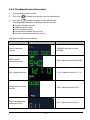
4.4.2 Checking Version Information .................................................................................... 4-11
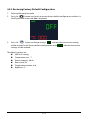
4.4.3 Restoring Factory Default Configuration ................................................................ 4-12
5 Troubleshooting ....................................................................................................... 5-1
5.1 Overview ........................................................................................................................................... 5-1
5.2 Parts Replacement ........................................................................................................................ 5-1

2
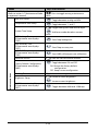
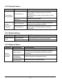
5.3 Troubleshooting Guide ............................................................................................................... 5-1
5.3.1 Power On/Off Failure ......................................................................................................... 5-1
5.3.2 Display Failures .................................................................................................................... 5-2
5.3.3 Button Failures..................................................................................................................... 5-2
5.3.4 Battery Failures .................................................................................................................... 5-2
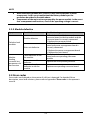
5.3.5 Module defective ............................................................................................................... 5-3
5.4 Error codes ....................................................................................................................................... 5-3
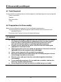
6 Disassembly and Repair .......................................................................................... 6-1
6.1 Tools Required ................................................................................................................................ 6-1
6.2 Preparations for Disassembly ................................................................................................... 6-1
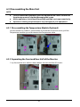
6.3 Disassembling the Main Unit .................................................................................................... 6-2
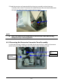
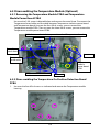
6.3.1 Disassembling the Temperature Module (Optional) ............................................. 6-2
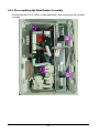
6.3.2 Separating the Front and Rear Half of the Monitor ............................................... 6-2
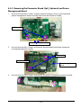
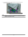
6.3.3 Removing the Parameter Connector Panel Assembly .......................................... 6-3
6.3.4 Disassembling the Main Bracket Assembly .............................................................. 6-4
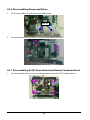
6.3.5 Removing the Parameter Board (SpO
2
Optional) and Power Management Board
............................................................................................................................................................. 6-5
6.3.6 Disassembling Pumps and Valves ................................................................................ 6-6
6.3.7 Disassembling AC/DC Power Board and Battery Converter Board .................. 6-6
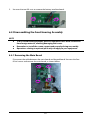
6.4 Disassembling the Front Housing Assembly ...................................................................... 6-7
6.4.1 Removing the Main Board .............................................................................................. 6-7
6.4.2 Removing the Display ....................................................................................................... 6-8
6.4.3 Removing the Keypad ...................................................................................................... 6-8
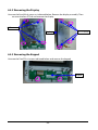
6.5 Disassembling the Temperature Module (Optional) ........................................................ 6-9
6.5.1 Removing the Temperature Module PCBA and Temperature Module Power
Board PCBA ..................................................................................................................................... 6-9
6.5.2 Disassembling the Temperature On-Position Detection Board PCBA ............ 6-9
7 Parts .......................................................................................................................... 7-1
7.1 Introduction .................................................................................................................................... 7-1
7.2 Main Unit .......................................................................................................................................... 7-1
7.2.1 Exploded View ..................................................................................................................... 7-1
7.2.2 Parts List ................................................................................................................................. 7-2
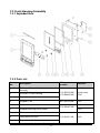
7.3 Front Housing Assembly ............................................................................................................ 7-3
7.3.1 Exploded View ..................................................................................................................... 7-3
7.3.2 Parts List ................................................................................................................................. 7-3
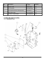
7.4 Main Bracket Assembly ............................................................................................................... 7-4
7.4.1 Exploded View ..................................................................................................................... 7-4
7.4.2 Parts List ................................................................................................................................. 7-5
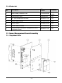
7.5 Power Management Board Assembly ................................................................................... 7-5
7.5.1 Exploded View ..................................................................................................................... 7-5
7.5.2 Parts List ................................................................................................................................. 7-6
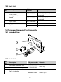
7.6 Parameter Connector Panel Assembly .................................................................................. 7-6
7.6.1 Exploded View ..................................................................................................................... 7-6
7.6.2 Parts List ................................................................................................................................. 7-6
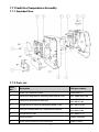
7.7 Predictive Temperature Assembly .......................................................................................... 7-7
7.7.1 Exploded View ..................................................................................................................... 7-7
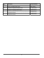
7.7.2 Parts List ................................................................................................................................. 7-7
8 Hardware and Software Upgrade ........................................................................... 8-1

3
8.1 Hardware Upgrade ........................................................................................................................ 8-1
8.1.1 Upgrade Package ................................................................................................................ 8-1
8.1.2 Upgrading Parameter Modules ..................................................................................... 8-1
8.1.3 Upgrading Temp ................................................................................................................. 8-2
8.1.4 Enabling Parameter Functions ....................................................................................... 8-2
8.2 Software Upgrade ......................................................................................................................... 8-2
A Electrical Safety Inspection .................................................................................... A-1
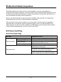
A.1 Power Cord Plug .......................................................................................................................... A-1
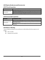
A.2 Device Enclosure and Accessories ........................................................................................ A-2
A.3 Device Labeling ........................................................................................................................... A-2

4
FOR YOUR NOTES

1-1
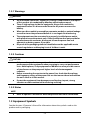
1 Introduction
1.1 Manual Information
A detailed revision history of this manual is recorded in the table below:
Version Revision History
1.0 New
2.0 Modify Temperature module test method, update parts list
3.0 Delete the equipment symbols
4.0 Update parts list for new cleaning and disinfecting agents
1.2 Safety Information
WARNING
Indicates a potential hazard or unsafe practice that, if not avoided, will
result in death or serious injury.
CAUTION
Indicates a potential hazard or unsafe practice that, if not avoided, could
result in minor personal injury or product/property damage.
NOTE
Provides application tips or other useful information to ensure that you
get the most from your product.

1-2
1.2.1 Warnings
WARNING
All installation operations, expansions, changes, modifications and repairs
of this product are conducted by Mindray authorized personnel.
There is high voltage inside the equipment. Never disassemble the
equipment before it is disconnected from the AC power source or the
battery.
When you disassemble/reassemble a parameter module, a patient leakage
current test must be performed before it is used again for monitoring.
The equipment must be connected to a properly installed power outlet
with protective earth contacts only. If the installation does not provide for
a protective earth conductor, disconnect it from the power line and
operate it on battery power, if possible.
Disposal of the packaging material should observe the applicable waste
control regulations and keeping it out of children’s reach.
1.2.2 Cautions
CAUTION
Make sure that no electromagnetic radiation interferes with the
performance of the equipment when preparing to carry out performance
tests. Mobile phone, X-ray equipment or MRI devices are a possible source
of interference as they may emit higher levels of electromagnetic
radiation.
Before connecting the receiver to the power line, check that the voltage
and frequency ratings of the power line are the same as those indicated on
the unit’s label or in this manual.
Protect the equipment from damage caused by drop, impact, strong
vibration or other mechanical force during servicing.
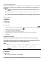
1.2.3 Notes
NOTE
Refer to operator’s manual for detailed operation and other information.
1.3 Equipment Symbols
See the Accutorr 3 Operator’s Manual for information about the symbols used on this
product and its packaging.

2-1
2 Theory of Operation
2.1 Overview
The monitor is intended for spot-check monitoring physiologic parameters, including SpO
2
,
Pulse Rate, NIBP and Temperature, on adult, pediatric, and neonatal patients in healthcare
facilities by clinical physicians or appropriate medical staff under the direction of physicians.
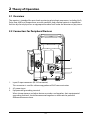
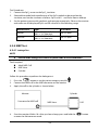
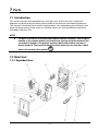
2.2 Connectors for Peripheral Devices
1. Input/Output connector (RS-232 connector)
This connector is used for software upgrade and DIAP communication.
2. AC power input
3. Equipotential grounding terminal:
When the equipment and other devices are to be used together, their equipotential
grounding terminals should be connected together to eliminate the potential
difference between them.
2
3
1

2-2
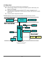
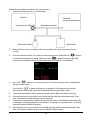
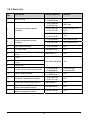
2.3 Main Unit
The main unit of the vital signs monitor consists of three parts:
Front housing assembly, consisting of main board, segment-code display, and
Power On/Off keypad;
Rear housing assembly: power module (AC/DC), power management and
interface board (including SpO2 isolation power), battery, NIBP module, and SpO2
board; and,
External module: Temperature module.
The following figure shows the main unit architecture of the vital signs monitor.
NIBP
connector
SpO
2
receptacle
15V
AC-DC power
module
AC-IN
Power
management
and interface
board
2600mAh
battery
Segment-code
display
Pump
RS232 port (for software upgrade
and DIAP communications.)
Front Housing Assembly
Rear Housing Assembly
NIBP module
External module
External connector
Power On/Off keypad
(indicator)
Main board
SpO
2
isolation power
Temperature
module
SpO
2
board
Temperature
probe

2-3
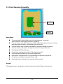
2.4 Front Housing Assembly
Main Board
The main board is the control center of the equipment. It provides
communication and display functions, including:
Communication with SpO2 board, and NIBP module through serial ports, starting
parameter measurement, and reading measured results;
Communication with Predictive temperature module through serial ports;
Communication with power management board through serial ports;
Extending an RS232 serial port;
Control over the Segment-code LCD display through I2C;
Providing backlight drive for segment-code display;
Recognition of keypad actions, and providing corresponding response;
Control over the beeper through IO port; and,
Providing 24 hour timing via the internal real time clock.
Keypad
The keypad contains the power switch, function keys and AC Battery indicator etc.
Main Board
Keypad

2-4
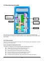
2.5 Rear Housing Assembly
Rear housing assembly consists of power module (AC/DC), power management and
interface board (including SpO
2
isolation power), battery compartment, NIBP module, and
SpO
2
board.
AC/DC Power Module
The AC/DC power board transforms the input AC into DC power, and is the power source for
all voltages in the equipment.
Power management and interface board
The power management interface board provides the following functions:
Charge and discharge of battery and charge detection;
DC/DC conversion: outputs 12V and 5V DC power;
Control over power On/Off key and AC, BAT indicator;
Communication transmission among parameter modules;
Providing isolation power for the SpO2 module; and,
Providing external connectors, filter and protection for these connectors.
AC/DC power
module
NIBP module
Battery
compartment
Power
management and
interface board
SpO
2
board

2-5
NIBP Module
The NIBP module consists of blood pressure measurement board and pump and valve
assembly, providing measurement acquisition of blood pressure data. The main functions of
the NIBP module are:
NIBP measurement; and,
Data exchange with the main board through the serial ports.
SpO
2
board
The SpO
2
board collects SpO
2
signals, processes SpO
2
algorithm and sends measurement
results to the main board. The power management interface board provides isolation power
for it.
2.6 External Module
An external Temperature module can be mounted on the monitor.
The independently developed Mindray Temperature module consists of an isolation power
board, Temperature measurement board, and probes. The Temperature measurement
board collects Temperature signals, processes algorithm and sends measurement results to
the main board.

2-6
FOR YOUR NOTES

3-1
3 Equipment Installation
3.1 Unpacking the Equipment
Open the package and remove the packing list. Check that all the articles included in the
packing list are available and the quantity and specification are correct. Make sure that:
All the optional parts purchased by the customer have been received.
Notify Mindray North America if your order is not correct or is incomplete. In case
of damage during transportation, keep the packing material and notify the
Mindray North America immediately.
Keep the packing material until all equipment is checked and accepted.
3.2 Preparation for Installation
3.2.1 Preparation for Installation Site
1. Ensure that the site meets all safety, environmental and power requirements.
2. Ensure that a network connector is available if the equipment is to be connected to
network.
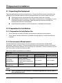
3.2.2 Environmental Requirements
To avoid explosion hazard, do not use the equipment in the presence of flammable
anesthetics, vapors or liquids. The environment where the equipment will be used should
be reasonably free from vibration, dust and corrosive substances. If these conditions are not
met, the system may not function normally.
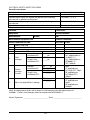
The environmental specification is as follows:
Main Unit
Item
Temperature (℃)
Relative humidity
(noncondensing)
Altitude (mmHg)
Operating
environment
0 to 40 (without
Temperature module)
5 to 40 (with Temperature
module)
15% to 95% 427.5 to 805.5
Storage
environment
-30 to 70 10% to 95% 120.0 to 805.5
NOTE
The environmental specifications of unspecified parameters are the same as
those of the main unit.

3-2
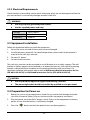
3.2.3 Electrical Requirements
Check that the system cables, power cords, and power plugs are not damaged, and that the
pins are not loose. In case of any damage, remove it from use.
WARNING
Use only properly grounded power outlets.
Use the supplied power cord only!
Voltage 100 to 240V AC
Current 0.9 to 0.5A
Frequency 50/60 Hz
3.3 Equipment Installation
Follow the procedure below to install the equipment:
1. Ensure the main unit and all accessories are not damaged.
2. Install the battery (optional). For detailed operations, please refer to the operator’s
manual of the vital signs monitor.
3. Connect AC power.
4. Connect the accessories.
The vital signs monitor can be mounted on a wall bracket or on a trolley support. The wall
bracket or trolley support can be ordered as an optional accessory. Each type of mounting
bracket is delivered with a complete set of mounting hardware and instructions. For
detailed installation information, please refer to Wall-mount Bracket Instructions for Use
(PN: 0010-20-42933) and Rollstand Instructions for Use (PN: 0010-20-42934).
CAUTION
Use only Mindray supplied or approved mounting solutions.
The mounting bracket should be installed by qualified service personnel.
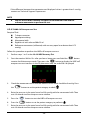
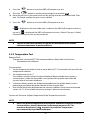
3.4 Preparation for Power on
1. Before you start using the equipment, check for any mechanical damage and make
sure that all external cables, plug-ins and accessories are properly connected.
2. Plug the power cord into the AC power source. If you run the equipment on battery
power, ensure that the battery is sufficiently charged.
3. Press the button on the front panel to turn on the equipment.
Page is loading ...
Page is loading ...
Page is loading ...
Page is loading ...
Page is loading ...
Page is loading ...
Page is loading ...
Page is loading ...
Page is loading ...
Page is loading ...
Page is loading ...
Page is loading ...
Page is loading ...
Page is loading ...
Page is loading ...
Page is loading ...
Page is loading ...
Page is loading ...
Page is loading ...
Page is loading ...
Page is loading ...
Page is loading ...
Page is loading ...
Page is loading ...
Page is loading ...
Page is loading ...
Page is loading ...
Page is loading ...
Page is loading ...
Page is loading ...
Page is loading ...
Page is loading ...
Page is loading ...
Page is loading ...
Page is loading ...
Page is loading ...
Page is loading ...
Page is loading ...
Page is loading ...
Page is loading ...
Page is loading ...
Page is loading ...
Page is loading ...
Page is loading ...
-
 1
1
-
 2
2
-
 3
3
-
 4
4
-
 5
5
-
 6
6
-
 7
7
-
 8
8
-
 9
9
-
 10
10
-
 11
11
-
 12
12
-
 13
13
-
 14
14
-
 15
15
-
 16
16
-
 17
17
-
 18
18
-
 19
19
-
 20
20
-
 21
21
-
 22
22
-
 23
23
-
 24
24
-
 25
25
-
 26
26
-
 27
27
-
 28
28
-
 29
29
-
 30
30
-
 31
31
-
 32
32
-
 33
33
-
 34
34
-
 35
35
-
 36
36
-
 37
37
-
 38
38
-
 39
39
-
 40
40
-
 41
41
-
 42
42
-
 43
43
-
 44
44
-
 45
45
-
 46
46
-
 47
47
-
 48
48
-
 49
49
-
 50
50
-
 51
51
-
 52
52
-
 53
53
-
 54
54
-
 55
55
-
 56
56
-
 57
57
-
 58
58
-
 59
59
-
 60
60
-
 61
61
-
 62
62
-
 63
63
-
 64
64


Ask a question and I''ll find the answer in the document
Finding information in a document is now easier with AI
Related papers
Other documents
-
 Tablette Store TabStore Counter Flex Assembly Instructions
-
Shenzhen PM-9000 Express User manual
-
Fujitsu Arrows M04 User manual
-
ADC 774 Series Maintenance Manual
-
Genius GHT-511 User manual
-
-
GE Panda User manual
-
Toshiba HT-201 User manual
-
Ultimate Healthcare UBAB0026-2 User manual
-
 TensCare SonicStimu CT2011 User manual

