Page is loading ...

P-047550-1448 ISSUE 10 © 2003
Installation Instructions for Catalog Series 48
AdaptaBeacon
Signals
Specifications
Edwards halogen models, 48SIN and 48FIN, are designed for use
where increased light output is required. The 20 watt halogen
bulbs are rated by the manufacturer at 226 lumens. The 25 watt
halogen bulbs are rated at 175 lumens.
Edwards 48FLED long life, flashing LED models are effective in
high noise level areas, especially where ear protection must be
worn and a visual status indicator is required. Edwards 48SLED
long life, steady-on LED models are suited for light duty appli-
cations where a continuous steady-on status indicator is required
and where ambient noise makes audible signals difficult to hear.
The 48 series signals can be mounted on 1/2" (13mm) NPT con-
duit (indoor or outdoor) or direct surface mounted (indoor). For
outdoor (weatherproof) installation, the signals must be conduit
mounted with their lens facing directly up. When installing in-
doors, these signals can be mounted in any position.
PLC Compatibility
The electrical input load requirements for PLC compatible sig-
naling devices are listed in Table 1. Signaling devices may be
directly connected to output cards that meet these requirements.
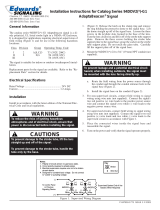
Figure 1. Conduit Mounting
Catalog Electrical Lamp
Number Rating Ratings
48SIN(*)-E1 12V DC 188 Lumens
†
1.0A 1,520 hr.
‡
48SIN(*)-G1-20WH 24V DC 226 Lumens
†
0.80A 20,000 hr.
‡
48SIN(*)-G5-20WH 24V 50/60 Hz 226 Lumens
†
0.80A 20,000 hr.
‡
48SIN(*)-N5-25WH 120V 50/60 Hz 175 Lumens
†
0.20A 20,000 hr.
‡
48SLED(**)-G1 24V DC 100,000 hr.
‡
0.062A
48SLED(**)-N5 120V 50/60 Hz 100,000 hr.
‡
0.022A
48FIN(*)-E1 12V DC 188 Lumens
†
1.0A 1,520 hr.
‡
48FIN(*)-G1-20WH 24V DC 226 Lumens
†
0.80A 25,000 hr.
‡
48FIN(*)-G5-20WH 24V 50/60 Hz 226 Lumens
†
0.80A 25,000 hr.
‡
48FIN(*)-N5-25WH 120V 50/60 Hz 175 Lumens
†
0.20A 25,000 hr.
‡
48FLED(**)-G1 24V DC 100,000 hr.
‡
0.062A
48FLED(**)-N5 120V 50/60 Hz 100,000 hr.
‡
0.022A
*Specify color of lens by adding one of the following letters to the cat.
number: A-amber, B-blue, C-clear, G-green, M-magenta, or R-red.
**Specify color of lens by adding one of the following letters to the cat.
number: A-amber, B-blue, G-green, or R-red.
†
Bulb manufacturer's Lumen rating.
‡
Projected lamp life based on manufacturer's calculated lamp life at 65
fpm and 50% duty cycle.
Lens
Mounting base
and lamp
support plate
1/2“ (13mm)
NPT conduit
(not supplied)
To field wiring
Locking
Mechanism
Description
The Catalog Series 48 Adaptabeacon signal is a UL and cUL listed
signaling appliance in a NEMA 4X enclosure. The signals are
suitable for indoor or outdoor (weatherproof) installation and are
available in AC and DC models as listed above.
Table 1. PLC Compatibility
Operating Maximum off state Continuous on Surge (inrush/duration)
Cat. No. voltage* leakage current (mA) current (mA) (A/ms**)
48SIN( )-G1-20WH 24V DC 25 800 0.9/1
48SIN( )-N5-25WH 120V AC 25 200 0.8/8
48SLED( )-G1 24V DC 4 65 0.07/1
48SLED( )-N5 120V AC 5 25 0.09/8
48FIN( )-G1-20WH 24V DC 25 800 2.2/100
48FIN( )-N5-25WH 120V AC 25 200 1.3/8
48FLED( )-G1 24V DC 4 65 0.07/1
48FLED( )-N5 120V AC 5 25 0.09/8
*All AC volts at 60 Hz
**Amps/milliseconds
Cheshire, CT 06410 203-699-3300 (Ph)
203-699-3365 (Cust. Serv. Fax)
203-699-3078 (Tech. Serv. Fax)

P-047550-1448 ISSUE 10
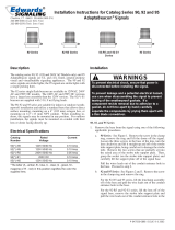
Figure 2. Direct Surface Mounting of the 48 Series
Signals
NOTE: Enclose wiring within an approved raceway
interconnecting the appliance and junction
box in accordance with governing codes,
standards and regulations.
Installation
Direct Surface Mounting (Indoor Only) - Figure 2
NOTE: AC signals may be direct surface mounted but are not
supplied with a direct surface mounting kit. The
installer should use suitable hardware appropriate for
the installation.
1. Insert a small flat blade screwdriver between the locking
mechanism and the lens. Gently push down and then pry up,
unseating the lens. Pull the lens up and off of the signal
mounting base, being careful not to damage the lamp.
2. Remove the two knockouts for mounting screws from the
signal base. Place the 3-3/4" (95mm) mounting gasket
provided in the direct surface mounting kit (DC models only)
on the mounting surface and mark the center of the three
holes in the gasket on the mounting surface. Remove the
gasket and drill a 3/8" (10mm) hole at each of the marked
positions.
3. Install the two rubber expansion plugs provided in the
hardware kit (DC models only) into the two outer holes in
the mounting surface.
4. Route the wire leads from the signal base through the center
hole in both the mounting gasket and surface. The wiring
should be run through an approved raceway or conduit
connected between the bottom of the signal base and an
approved junction box (not supplied). Bring wire leads into
the junction box. Refer to the signal's label for voltage rating.
5. Align the outer holes in the mounting gasket with the holes
in the surface. Insert two screws with lockwashers through
the two outer holes in the signal base and align the screws
with the rubber expansion plugs as shown in Figure 2. Press
the signal base firmly against the mounting surface and tighten
the screws.
6. Connect the field wiring to the signal wire leads as described
in the Wiring Section.
Wiring
1. For AC models, use wire nuts (not supplied) and connect the
signal's black and white wire leads to the power source wires.
Polarity is not important.
2. For DC models, connect the signal's red wire to the positive
power source wire and connect the signal's black wire to the
negative power source using appropriate connectors (not
supplied). Polarity must be observed.
Troubleshooting
If the signal light fails to operate, make sure there is power to the
signal. If there is power and the light still fails to operate, replace
the lamp as directed in the "lamp replacement" section.
Maintenance
Cleaning
To field wiring
One of two
knockouts for
direct surface
mounting
Lens
(2) Mounting
screws (supplied with
DC models)
(2) Lockwashers (supplied
with DC models)
Mounting base
and lamp
support plate
Mounting gasket
(supplied with DC
models)
(2) Rubber expansion
plugs (supplied with
DC models)
Mounting surface
Enclose in
Raceway
CAUTION
To prevent damage to the lens, do not use abrasive
materials or cleaners.
WARNING
To prevent electrical shock, ensure that power is
disconnected before installing the signals.
WARNING
To prevent leakage and a potential shock hazard,
when mounting outdoors the signal must be
installed with the lens or dome facing directly up.
Install in accordance with the latest edition of the National Elec-
trical Code and local regulations. Install the signals using one of
the following applicable mounting procedures.
Conduit Mounting (Indoor or Outdoor) - Figure 1
1. Route the signal's wire leads through 1/2" (13mm) NPT
conduit (not supplied) and thread the conduit into the signal
mounting base.
2. Connect the field wiring to the signal wire leads as described
in the Wiring Section.
Periodically clean the Adaptabeacon lens surface with a soft cloth
or sponge and water or a mild detergent solution to maintain op-

P-047550-1448 ISSUE 10
Figure 3. Lamp Replacement
Replacement Parts
Component Catalog or Part Number
Halogen Lamp - 48SIN(*)-N5-25WH, 48FIN(*)-N5-25WH 50LMP-25WH or
Industry Trade No. 15T7DC**
Halogen Lamp - 48SIN(*)-G1-20WH, 48SIN(*)-G5-20WH, 50LMP-20WH or
48FIN(*)-G1-20WH, 48FIN(*)-G5-20WH Industry Trade No. 1692**
Incandescent Lamp - 48SIN(*)-E1, 48FIN(*)-E1 Industry Trade No. 94
Lens (Amber, Blue, Clear, Green, Magenta or Red) - 48FIN and 96-L(*)
48SIN Series
Lens (Amber, Blue, Green, Red) - 48FLED and 48SLED Series 96-L(*)
*Specify color of lens by adding one of the following letters to the catalog number: A-amber, B-blue,
C-clear, G-green, M-magenta, or R-red. Example: A red lens for the 48SIN series signal is 96-LR.
**The non-halogen bulb listed may be used in the halogen bulb models.
1. Insert a small flat blade screwdriver between the locking
mechanism and the lens. Gently push down and then pry up,
unseating the lens. Pull the lens up and off of the signal
mounting base.
2. Gently push down on the lamp, twist and pull up to remove
the lamp from its socket. Install the new lamp by aligning
the connector on the base of the tube with its mating socket,
then carefully press down into the socket. Assemble the
signal.
3. Apply power to the signal and verify that the signal operates
properly.
WARNINGS
To prevent injury, do not remove or insert lamp
when unit is energized.
To prevent leakage and potential electrical shock,
use care when disassembling the signals to
prevent tearing of the weatherproof gaskets.
timum light visibility. Ensure that the lens is completely dry
before assembling the signal.
Lamp Replacement (non-LED models only)
CAUTION
To prevent property damage and injury,
do not
touch glass with bare fingers. Grasp glass with a
soft, clean cloth or with packaging supplied with
the replacement lamp.
Refer to the "Replacement Parts" section, for the required type of
lamp. After disconnecting power, replace the lamp as follows:
Refer to Figure 3.
/