Page is loading ...

P-047550-1641 ISSUE 5 © 1998
FARMINGTON, CT 203-699-3000 FAX 860-677-7746
Installation Instructions for Catalog Series
58-N5-100WH AdaptaBeacon
Signals
EDWARDS
Install in accordance with the latest edition of the National Elec-
trical Code and local regulations.
1. Unfasten and remove the clamp ring. Lift off the dome.
2. Remove the three screws in the rotating lamp assembly
mounting plate, lift the assembly off the base and pull the
wire leads out of the conduit entrance hole in the base.
3. For indoor, non-hazardous installation, the signal may be
direct surface mounted or mounted on 3/4" (19mm) NPT
conduit. For outdoor (weatherproof) and hazardous location
installation, the signal must be conduit mounted. Install the
signal base using one of the following applicable mounting
procedures.
Direct Surface Mounting (indoor, non-hazardous
location installation only)
NOTE: For direct surface mounting, the signal must be
installed with its dome facing either directly up or
down.
• Remove the three mounting screw knock-outs from the bottom
of the signal base.
• Route the field wiring from the 120V AC power source
through the conduit entrance hole in the base.
• Fasten the base to the surface by installing three #10 wood
screws (not supplied) or other suitable hardware through the
knock-out holes in the base. Proceed to step 4 for wiring
connections.
Conduit Mounting (hazardous location, indoor or
outdoor installation)
Description
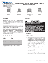
The Adaptabeacon Catalog Series 58-N5-100WH signal is a UL
Listed, general purpose visual signaling appliance. The signal
is supplied in a UL Listed NEMA 4X enclosure. This signal is
suitable for installation in the hazardous locations outlined be-
low:
Class Division Group Operating Temp. Code
I 2 A,B,C,D T1 (450ºC, 842ºF)
II 2 F,G T6 (85ºC, 185ºF)
III 1 and 2 T6 (85ºC, 185ºF)
The 58-N5-100WH contains a 100 watt halogen rotating bea-
con which is motor driven at 75 rpm. The signal operates on
120V AC, 50/60 Hz at 1.0 amp.
The 58-N5-100WH signal is suitable for indoor or outdoor
(weatherproof) installation and utilizes a standard base that al-
lows for direct surface mounting or mounting on 3/4" (19mm)
NPT conduit. For outdoor installation, the signal must be con-
duit mounted.
Installation
WARNINGS
To reduce the risk of ignition of hazardous atmo-
spheres or risk of electrical shock, keep assembly
tightly closed when circuits are energized. Discon-
nect power before disassembling enclosure or
removing or replacing lamp.
To prevent leakage and a potential shock hazard,
use care when disassembling the signal to prevent
tearing the gasket.
WARNING
To prevent leakage and a potential shock hazard,
when mounting outdoors the signal must be
installed with the lens or dome facing directly up.
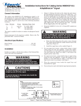
Figure 1. Catalog Series 58-N5-100WH Signal
• Route the field wiring from the 120V AC power source
through the conduit entrance hole in the base.
• Install the base on the conduit (not supplied).
4. Using wire nuts (not supplied), connect the field wiring to
the signal's wire leads. Connect one field wire to a wire lead
from each the motor assembly and the strobe tube. Connect
the other field wire to the other wire lead from each the motor
assembly and the strobe tube.
Connect the ground wire to the ground screw in the base of
the unit.
5. Place the connected wires inside the base of the signal and
reassemble the signal on the base using the three screws
removed in step 2.

6. Ensure that the dome gasket is properly installed and replace
the signal dome and secure with the clamp ring removed in
step 1.
7. Turn on power and verify that the signal operates properly.
Maintenance
WARNINGS
To reduce the risk of ignition of hazardous atmo-
spheres or risk of electrical shock, keep assembly
tightly closed when circuits are energized. Discon-
nect power before disassembling enclosure or
removing or replacing lamp.
To prevent leakage and a potential shock hazard,
use care when disassembling the signal to prevent
tearing the gasket.
Should the lamp fail to operate, check that power is on. If power
is on, replace the lamp as directed in the Lamp Replacement sec-
tion.
WARNINGS
To prevent electrical shock, do not remove or insert
lamp when unit is energized.
Lamp Replacement
1. Unfasten and remove the clamp ring. Lift off the dome.
2. Remove the lamp by pushing it up slightly and turning
counterclockwise.
3. Refer to the "Replacement Parts" section and replace the lamp
using the cover supplied with the lamp.
4. Ensure that the dome gasket is properly installed and replace
the signal dome and secure with the clamp ring removed in
step 1.
Cleaning
The signal's dome should be periodically cleaned to maintain
optimum light visibility. Clean the dome with a soft cloth or
sponge using water and a mild detergent.
1. Unfasten and remove the clamp ring. Lift off the dome.
2. Clean the dome with a soft cloth or sponge using water and a
mild detergent.
3. Ensure that the dome is completely dry and the gasket
properly installed. Replace the signal dome and secure with
the clamp ring removed in step 1.
Replacement Parts
Replacement lamps and domes may be obtained from your Edwards distributor. The catalog numbers are listed below.
Replacement Component Replacement Component
Catalog or Part Number
Lamp - 100 Watt Halogen double Phillips 100Q/CL/DC/120V or
contact, bayonet base equivalent
Dome (Amber, Blue, Clear, Green, 94DV2-D(*)
Magenta, or Red)
*Specify color of dome by adding the letter A-Amber, B-Blue, C-Clear, G-Green, M-Magenta or R-Red to this order number.
P-047550-1641 ISSUE 5
/


