Page is loading ...

P/N 3100382 ISSUE 1 © 2001
Installation Instructions for DC Power Supplies
Catalog Numbers S-25-24, S-40-24 and S-60-24
Description and Operation
Edwards DC power supplies are easy to install, convection
cooled low voltage power sources designed to operate
DC powered products including bells, buzzers, horns and
beacons.
Installation
1. Mount the power supply using one of the following
methods.
a. Mount using (2) M3 threaded holes located on
either the side or the bottom of the power supply.
OR
b. Mount the power supply using the (2) predrilled
3.5 mm holes located on either the side or the
bottom of the power supply.
NOTE: Pre-drilled holes on Cat. Nos. S-40-24 and S-60-24
are accessible without removal of cover.
For Cat. No. S-25-24 only, remove the single screw
(located in the corner of the power supply) securing
the cover on the power supply. Slide the cover
back and then lift up and remove the cover.
Replace the cover on the Cat. No. S-25-4 power
supply and secure using screw removed in step
1.b.
CHESHIRE, CT 203-699-3300 FAX 203-699-3365 (CUST. SERV.) 203-699-3078 (TECH SERV.)
WARNING
Prior to making connections, ensure the supply voltage is
turned off to prevent accidental electric shock.
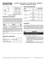
2. Connect supply wiring to terminal block TB1 (Figure
1, 2 or 3) as follows. Using a three-wire cord, connect
the black conductor (Line) to the terminal labeled "L",
connect the white conductor (Neutral) to the terminal
labeled "N" and connect the green conductor (Ground)
to the terminal labeled .
3. Connect a wire from the positive side of the load to
the terminal screw labeled "V+". Connect a wire from
the negative side of the load to the terminal screw
labeled "V-".
4. After all electrical connections have been made, turn
on the supply voltage. The green power LED should
illuminate indicating voltage output.
The output is factory set for 24V DC and no adjustment
should be required. However, if voltage adjustment
is necessary, turn the voltage adjustment
potentiometer "SVR1" counterclockwise to lower the
voltage or clockwise to increase the voltage. The
voltage is adjustable from 21.6V to 26.4V.
V ADJ
-V +V
L
N
(AC In)DC Out
S-25
Screw holding
cover in place
Power LED
(Green)
Terminal
Block TB-1
Voltage Adjustment
Potentiometer
Figure 1. Catalog Number S-25-24
3 3/4"
(97 mm)
3 7/8"
(98.5 mm)
1 3/8"
(54 mm)
(2) M3
threaded
holes
Table 1. Electrical Specifications
Output Power
Catalog Number Input Power Volts Watts
S-25-24 85 - 264V AC 47-63 Hz 24V DC 25
S-40-24 85 - 264V AC 47-63 Hz 24V DC 40
S-60-24 85 - 264V AC 47-63 Hz 24V DC 60

P/N 3100382 ISSUE 1
PAGE 2
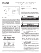
Figure 2. Catalog Number S-40-24
V ADJ
-V +V
L
N
(AC In) (DC Out)
Power LED
(Green)
Terminal
Block TB-1
Voltage Adjustment
Potentiometer
3 3/4"
(97 mm)
5"
(197 mm)
1 3/8"
(54 mm)
(3) M3
threaded
holes
Figure 3. Catalog Number S-60-24
V ADJ
-V +V
L
N
(AC In) (DC Out)
Power LED
(Green)
Terminal
Block TB-1
Voltage Adjustment
Potentiometer
3 3/4"
(97 mm)
6 1/4"
(246 mm)
1 3/8"
(54 mm)
(3) M3
threaded
holes
/