Page is loading ...

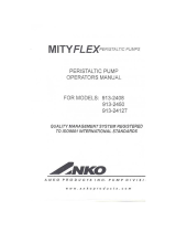
KA7E WITH STAND ACCESSORY SHOWN
KA SERIES ELECTRIC ROTARY
OVENS
Information in this manual superceedes TSB 1406.
KA7E ML-137701 SELF-CLEAN, GLASS BACK
ML-137709 SELF-CLEAN, SOLID BACK
KA7EM ML-137710 MANUAL-CLEAN, GLASS
BACK WITH GREASE ASSIST
ML-137711 MANUAL-CLEAN, GLASS
BACK WITHOUT GREASE
ASSIST
ML-137713 MANUAL-CLEAN, SOLID BACK
WITH GREASE ASSIST
ML-137714 MANUAL-CLEAN, SOLID BACK
WITHOUT GREASE ASSIST
- NOTICE -
This Manual is prepared for the use of trained Hobart Service
Technicians and should not be used by those not properly
qualified.
This manual is not intended to be all encompassing. If you have
not attended a Hobart Service School for this product, you should
read, in its entirety, the repair procedure you wish to perform to
determine if you have the necessary tools, instruments and skills
required to perform the procedure. Procedures for which you do
not have the necessary tools, instruments and skills should be
performed by a trained Hobart Service Technician.
The reproduction, transfer, sale or other use of this Manual,
without the express written consent of Hobart, is prohibited.
This manual has been provided to you by ITW Food Equipment
Group LLC ("ITW FEG") without charge and remains the property
of ITW FEG, and by accepting this manual you agree that you will
return it to ITW FEG promptly upon its request for such return at
any time in the future.
SERVICE MANUAL
A product of Hobart Service 701 S. Ridge Ave Troy, OH 45374
F25294 Rev. A (0412)

TABLE OF CONTENTS
GENERAL .................................................................................................. 4
REFERENCE INFORMATION .......................................................................... 4
TSB'S & TSI'S ...................................................................................... 4
INSTRUCTIONS & SPECIFICATIONS .............................................................. 4
INTRODUCTION ....................................................................................... 4
ELECTRICAL SPECIFICATIONS ....................................................................... 5
WATER SUPPLY REQUIREMENTS (KA7E ONLY) ...................................................... 5
TOOLS ................................................................................................. 5
ACCESSORY STAND INSTRUCTIONS ................................................................. 5
KA7E SELF-CLEAN (ML-137701, ML-137709) ...................................................... 5
KA7EM WITH GREASE ASSIST (ML-137710, ML-137713) .......................................... 7
KA7EM WITHOUT GREASE ASSIST (ML-137711, ML-137714) ..................................... 8
TETHER BRACKET AND OVEN MOUNTING TO STAND (KA7E, KA7EM) ........................... 9
REMOVAL AND REPLACEMENT OF PARTS .............................................................. 10
COVERS .............................................................................................. 10
PUMP COVER .................................................................................... 10
RIGHT SIDE COVER .............................................................................. 10
LEFT SIDE COVER ............................................................................... 10
TOP COVER (CONTROL PANEL) ................................................................. 10
TOP COVER ...................................................................................... 10
FAN COVER ...................................................................................... 11
DOOR ................................................................................................ 11
DOOR ADJUSTMENT ............................................................................. 12
DOOR SWITCH ADJUSTMENT (KA7E ONLY; IF REQUIRED) ..................................... 12
DOOR SWITCH MAGNET (KA7E ONLY) .............................................................. 13
OUTER DOOR GLASS ................................................................................ 13
WASH ARM, STRAINER PANS, STRAIN PAN SUPPORT, DRAIN SHROUD (KA7E ONLY) ............. 13
LAMP ................................................................................................. 14
FAN MOTORS ASSEMBLY ............................................................................ 15
HEATING ELEMENTS ................................................................................ 17
HIGH LIMIT THERMOSTAT ........................................................................... 18
TEMPERATURE SENSOR ............................................................................ 18
CONTACTORS ....................................................................................... 19
POWER SWITCH AND MOMENTARY SWITCHES .................................................... 19
DISPLAY BOARD AND KEYPAD ...................................................................... 20
ROTOR STOP/START SWITCH ....................................................................... 21
MEAT PROBE MINI JACK ............................................................................. 22
CAPACITORS ........................................................................................ 22
WATER LEVEL CONTROL BOARD (KA7E ONLY) ..................................................... 23
WATER LEVEL SENSOR (KA7E ONLY) ............................................................... 24
CHEMICAL SENSOR (KA7E ONLY) ................................................................... 24
WASH PUMP RELAY (KA7E ONLY) ................................................................... 24
TRANSFORMER ...................................................................................... 25
CPU BOARD .......................................................................................... 25
PERISTALTIC PUMPS ................................................................................ 26
PUMP REMOVAL ................................................................................. 26
PROCEDURE TO REPLACE PUMP HOSE ........................................................ 26
WATER FILL VALVE (KA7E ONLY) .................................................................... 28
WASH PUMP (KA7E ONLY) ........................................................................... 28
DRAIN PUMP (KA7E ONLY) ........................................................................... 29
DRIVE MOTOR ASSEMBLY ........................................................................... 29
DRIVE MOTOR ADJUSTMENT .................................................................... 31
DRIVE MOTOR, SPEED REDUCER AND GEARBOX .................................................. 33
SERVICE PROCEDURES AND ADJUSTMENTS ........................................................... 36
SERVICE MODE - PROGRAMMING AND DIAGNOSTICS ............................................. 36
KA SERIES ELECTRIC ROTARY OVENS
F25294 Rev. A (0412) Page 2 of 72

PROCEDURE TO ENTER SERVICE MODE ....................................................... 36
PROCEDURE TO TOGGLE BETWEEN NO ID AND OPERATOR ID MODE ........................ 36
PROCEDURE TO TOGGLE BETWEEN 9 AND 99 PROGRAMS .................................... 36
SERVICE MODE PARAMETERS .................................................................. 36
DEMO MODE (KA7E ONLY) ........................................................................... 41
RETURN TO NORMAL MODE ..................................................................... 43
TEMPERATURE SENSOR TEST ...................................................................... 43
HEATING ELEMENT TEST ............................................................................ 44
PUMP, K3 RELAY COIL TESTS ....................................................................... 44
CONTROLS CALIBRATION ........................................................................... 44
CALIBRATION PROCEDURE ..................................................................... 44
ELECTRICAL OPERATION ................................................................................ 46
COMPONENT FUNCTION ............................................................................ 46
SEQUENCE OF OPERATION ......................................................................... 46
PROGRAMMED COOKING ....................................................................... 46
WASHING CYCLE SEQUENCE OF OPERATIONS ................................................ 47
USER PRESSES CLEAN BUTTON ................................................................ 47
CONTROLS EXPLANATION .......................................................................... 48
MODEL KA7E ..................................................................................... 48
MODEL KA7EM ................................................................................... 49
COMPONENT LOCATIONS ........................................................................... 50
MODEL KA7E ..................................................................................... 50
MODEL KA7EM ................................................................................... 52
WIRING DIAGRAMS .................................................................................. 54
KA7E - COMPONENT CONNECTIONS ............................................................ 54
KA7EM - COMPONENT CONNECTIONS .......................................................... 55
POWER CONNECTION ........................................................................... 56
SCHEMATIC DIAGRAMS ............................................................................. 57
MODEL KA7E ..................................................................................... 57
MODEL KA7EM ................................................................................... 59
PLUMBING DIAGRAMS (KA7E ONLY) ................................................................ 62
TROUBLESHOOTING ..................................................................................... 64
TROUBLESHOOTING ................................................................................. 64
TROUBLESHOOT ROTOR COMPONENTS ........................................................... 67
APPENDIX ................................................................................................ 69
REVERSING CONTROLS ............................................................................. 69
KA SERIES ELECTRIC ROTARY OVENS
© HOBART SERVICE 2012
Page 3 of 72 F25294 Rev. A (0412)

GENERAL
Oven cleaners are corrosive and can cause chemical burns. Rubber gloves, goggles and protective
clothing are required. Read and follow the instructions for the oven cleaner.
Safety standards require that, when the rotary oven’s electric supply line is properly connected to the
electrical power supply, an adequate means must be provided to limit movement of the oven without applying stress
to the electrical conduit. This means that, as part of the installation, the oven must be secured to either the wall or
the floor to limit movement of the oven and, thus, preventing damage to the flexible electrical conduit during cleaning,
maintenance and service operations.
REFERENCE INFORMATION
TSB'S & TSI'S
NOTE: Links or references to the TSB's are provided
here and in the appropriate sections of service
manual.
TSB 1381 KA7E ROTARY OVEN SCRAMBLED VFD DISPLAY.
TSB 1383
ROTISSERIE OVENS HR5E, HR7E AND KA7E NEW DRIVE MOTOR
ASSEMBLIES.
See Multimedia
section in TIS.
TSB 1400 KA7E - LEAKS AT DRIVE ARM GASKET DURING WASH CYCLE.
TSB 1417 KA7E - CLOGGING AT INPUT AND OUTPUT OF PERISTALTIC PUMPS.
See Multimedia
section in TIS.
TSI
HR7E AND KA7E ROTISSERIE OVEN ROTOR CRANK ARM DISENGAGING
FROM ROTOR.
See Multimedia
section in TIS.
Instructions & Specifications
Model Specifications Instructions Manual
KA7E F-40182 F-35521
KA7EM F-40287 F-45111
INTRODUCTION
All pictures and illustrations shown are of a KA7E
unless otherwise specified. When specific model
number designations are needed for clarity, they are
added to the procedure or picture.
General
• Capacity of the KA series seven spit oven is 21
to 35 chickens.
• Stacking kit available to stack ovens.
• Refer to the Specifications sheet for oven
Installation details and Instructions manual for
operating and cleaning instructions.
KA7E - Model Description
• Rotisserie oven with automatic clean cycle.
• Electronic control with message center, time,
temperature and program display features.
• Pass through controls on the unload side to
snooze cook cycle, silence beeper and stop cook
cycle.
• Equipped with grease assist and chemical
cleaner peristaltic pumps.
• Pump for automatic draining.
KA7EM - Model Description
• Rotisserie oven without automatic clean cycle
features (manual cleaning).
• Electronic control with time, temperature and
program display features.
• Manual drain valve.
KA SERIES ELECTRIC ROTARY OVENS - GENERAL
F25294 Rev. A (0412) Page 4 of 72

• Equipped with grease assist and chemical
cleaner peristaltic pumps.
• Available with a grease assist peristaltic pump to
remove grease during a cook cycle (optional).
ELECTRICAL SPECIFICATIONS
KA7E AND KA7EM
VOLTS PHASE WATTAGE AMPERAGE
208 1 9,300 42.8
208 3 9,300 24.7
240 1 9,300 37.7
240 3 9,300 21.8
NOTE: Separate power supplies must be used when
stacking two ovens.
INSTALLATION NOTE:
Before putting oven into service, check to ensure
incoming power terminal block TB6 wire retaining
screws are tight.
Ovens mounted on casters or installed on stands with
casters must be provided with an adequate restraining
means to guard against transmission of strain to the
electric supply line. Instructions for tethering are
included in stacking kit instructions and with optional
oven stand. Disconnect the flexible electrical
conduit(s) before disconnecting the restraint.
WATER SUPPLY REQUIREMENTS
(KA7E ONLY)
NOTE: For proper operation, use only HOT water
supply. For installations at the end of a long hot water
line, a second pre-rinse may be required to be
programmed to prime the line.
Hot water supply:
• 3/4" hose bib fitting.
• 0.5 GPM @ 25-50 PSI.
• 120°F - 140°F.
• Recommended hardness, 4 - 6 grains.
• Minimum conductivity required, 30
MICROMHOS/CM.
TOOLS
• Standard set of hand tools
• VOM with AC current tester (Any VOM with a
sensitivity of at least 20,000 ohms per volt can be
used.)
• Temperature Tester
• Field Service Grounding Kit
• Torque wrench capable of measuring up to 45 in-
lbs.
• Jewelers screwdriver
• Power switch and momentary switch removal
tool (two required) made locally to dimensions in
graphic below
NOTE: Material for tool can be aluminum, hard plastic
or any other hard material which can be easily
fabricated to dimensions.
Fig. 1
ACCESSORY STAND
INSTRUCTIONS
NOTE: Separate units can be lifted by means of a
forklift. To do this, open both doors. Remove fan
cover. Slide forks all of the way thru top of oven. Make
sure forks rest on the frame member and are spread
as far apart as possible. Stacked units must not be
lifted in this manner.
KA7E Self-Clean (ML-137701, ML-137709)
1. Remove Right Side Cover.
2. With oven lifted, remove drain plug and save it.
Drain hose is connected here and routed down
thru base.
3. Remove electric power cord blank and install
proper restraining fitting for power cord.
KA SERIES ELECTRIC ROTARY OVENS - GENERAL
Page 5 of 72 F25294 Rev. A (0412)

BOTTOM VIEW SHOWN
4. Remove screws securing water fill valve to utility
plate.
5. Remove screws securing drain manifold to utility
plate and utility plate to frame.
6. Current construction - Remove strain relief nuts
securing chemical-in and grease-out hoses.
A. Remove hoses from strain relief fittings (pull
hoses through fittings but leave connected
to machine).
CURRENT CONSTRUCTION
7. Previous construction - Remove chemical-in and
grease-out hoses from 45 degree strain relief
fittings.
PREVIOUS CONSTRUCTION
Fig. 5
8. Discard original utility plate, saving screws.
9. Slide mounting bracket off water fill valve.
Fig. 6
10. Reinstall mounting bracket to water fill valve
(rotated as shown).
KA SERIES ELECTRIC ROTARY OVENS - GENERAL
F25294 Rev. A (0412) Page 6 of 72

Fig. 7
11. Install water valve onto bracket on new utility
plate (supplied with stand).
Fig. 8
12. Install new utility plate onto oven using screws
removed earlier.
13. Install drain plug removed earlier.
14. Install new hoses supplied with oven and route
down into base.
Fig. 9
15. Route water supply through the bottom of the
stand and connect. (Fittings mate to ¾ inch male
hose bib, not supplied.)
16. Route water drain through the bottom of the
stand and connect. (Fittings mate to 1 inch
female NPT, not supplied.)
17. Route chemical-in and grease-out hoses down
through bottom of machine into stand. Connect
hoses to grease vessel and chemical container.
18. Route power cord thru base into oven and
connect to terminal block.
19. Proceed to Tether Bracket and Oven Mounting to
Stand (KA7E, KA7EM).
KA7EM with Grease Assist (ML-137710,
ML-137713)
1. Remove Right Side Cover.
2. Remove electric power cord blank. Install power
cord restraining fitting (not supplied) in the proper
hole E1.
Fig. 10
KA SERIES ELECTRIC ROTARY OVENS - GENERAL
Page 7 of 72 F25294 Rev. A (0412)

3. Remove screws and valve bracket from factory
standard utility plate.
4. Save screws and bracket. Discard original
factory standard utility plate.
5. Remove grease-out hose from 45 degree strain
relief fitting.
Fig. 11
6. Install valve bracket from old plate onto new utility
plate (supplied with stand).
7. Install new utility plate assembly onto oven using
screws removed earlier.
8. Install ¾" MNPT to ¾" ID, 90 deg, Barb Hose
Fitting (not supplied) into P1 drain connection.
NOTE: P1 drain connection cannot drop through into
stand and must exit out the right side of the oven.
9. Route grease-out hose down through bottom of
machine into stand.
10. Route power cord through stand up into oven and
connect to terminal block.
11. Proceed to Tether Bracket and Oven Mounting to
Stand (KA7E, KA7EM).
KA7EM without Grease Assist (ML-137711,
ML-137714)
1. Remove Right Side Cover.
2. Remove electric power cord blank. Install power
cord restraining fitting (not supplied) in the proper
hole E1.
Fig. 12
3. Remove screws from factory standard utility
plate.
Fig. 13
4. Install ¾" MNPT to ¾" ID, 90 deg, Barb Hose
Fitting (not supplied) into P1 drain connection.
5. Install new utility plate (supplied with stand)
assembly onto oven using screws removed
earlier.
6. Install Plug Button (supplied with stand
accessory) into new utility plate.
KA SERIES ELECTRIC ROTARY OVENS - GENERAL
F25294 Rev. A (0412) Page 8 of 72

Fig. 14
7. Route power cord through stand up into oven and
connect to terminal block.
8. Proceed to Tether Bracket and Oven Mounting to
Stand (KA7E, KA7EM).
Tether Bracket and Oven Mounting to Stand
(KA7E, KA7EM)
1. Ensure that tether bracket is installed.
A. The bracket must be installed along with
one of the swivel casters to a corner as
shown using the caster hardware provided.
The remaining open hole in the center of the
tether bracket is to be used to secure one
end of the tether (locally supplied chain,
cable, etc.). The other end of the tether is to
be secured to an anchoring point in the wall
or floor when oven installation is complete.
Make sure that during oven movement, no
stress is applied to the flexible electrical
conduit(s).
Fig. 15
2. Using holes in oven's caster mounting plate,
secure oven to stand using 4 screws and 4
washers provided with stand accessory. Install
washers such that bolt does not slip through.
Fig. 16
3. Install all removed covers.
4. Continue with installation per Instructions
Manual.
KA SERIES ELECTRIC ROTARY OVENS - GENERAL
Page 9 of 72 F25294 Rev. A (0412)

REMOVAL AND REPLACEMENT OF PARTS
Due to use of chemical detergents, all interior replacement hardware must be stainless steel hardware
as listed in the parts catalog.
COVERS
Disconnect the
electrical power to the machine and
follow lockout / tagout procedures.
Pump Cover
1. Remove two thumbscrews securing pump cover
and lift cover off.
2. Reverse procedure to install.
NOTE: Anytime service is performed requiring the
right side cover to be removed, check to ensure
incoming power terminal block wire retaining screws
are tight.
Right Side Cover
1. Remove Pump Cover.
2. Remove twelve screws securing right side cover
to frame.
3. Loosen one screw securing top center of cover.
Fig. 17
4. Remove cover.
5. Reverse procedure to install.
Left Side Cover
1. Remove ten screws securing left side cover to
frame.
2. Loosen one screw securing top center of cover.
Fig. 18
3. Remove cover.
4. Reverse procedure to install.
Top Cover (Control Panel)
1. Remove screws securing top cover over controls
area.
2. Remove cover.
3. Reverse procedure to install.
Top Cover
1. Remove screws securing Top Cover (Control
Panel).
2. Remove cover.
3. Remove remaining screws securing top cover
and lift cover off.
KA SERIES ELECTRIC ROTARY OVENS - REMOVAL AND REPLACEMENT OF PARTS
F25294 Rev. A (0412) Page 10 of 72

Fig. 19
4. Reverse procedure to install.
Fan Cover
1. Open door.
2. Remove nut securing fan cover to top of cavity.
3. Grab deflector edge and pivot edge toward you
to disengage cover from studs.
4. Slide cover off studs at opposite side and remove
cover.
NOTE: Fan cover can be removed thru either door in
the same manner.
VIEW - AS LOOKING THROUGH DOOR GLASS
5. Reverse procedure to install.
NOTE: Make sure all six studs are engaged properly
and that the cover does not hang down.
DOOR
Disconnect the
electrical power to the machine and
follow lockout / tagout procedures.
1. Remove Left Side Cover.
2. Open oven door and pull inner oven door to
overcome magnet hold to main door.
Fig. 21
3. Lift inner door hinge pins out of hinge bushings
and lay door on a flat padded surface.
Fig. 22
4. Remove screws securing facade to oven.
KA SERIES ELECTRIC ROTARY OVENS - REMOVAL AND REPLACEMENT OF PARTS
Page 11 of 72 F25294 Rev. A (0412)

Fig. 23
5. Close door.
6. Remove nuts securing top hinge to cabinet.
Fig. 24
7. Carefully remove hinge plate while supporting
hinge backing plate and lift door off lower hinge
pin.
Fig. 25
8. Reverse procedure to install but leave nuts
securing hinge plate loose. Perform Door
Adjustment.
Door Adjustment
1. With top hinge plate mounting nuts loose, use an
object to shim handle end of door to make bottom
of door parallel to the sump facade.
Fig. 26
2. Tighten hinge plate nuts and check door
operation. Make sure there is no interference or
rubbing when door is operated. Door must not
contact sump facade when opening or closing.
3. Check Door Switch Adjustment (KA7E only; if
required). LED at CPU board input X22 should
be on when both doors are closed and both door
switches are closed.
Door Switch Adjustment (KA7E only; if required)
1. With oven top facade removed to access door
switch, loosen switch mounting screws and
adjust switch as required. LED at CPU board
input X22 should be on when both doors are
closed and both door switches are closed.
2. Install all covers and check for proper operation.
Fig. 27
KA SERIES ELECTRIC ROTARY OVENS - REMOVAL AND REPLACEMENT OF PARTS
F25294 Rev. A (0412) Page 12 of 72

DOOR SWITCH MAGNET (KA7E
ONLY)
Disconnect the
electrical power to the machine and
follow lockout / tagout procedures.
1. Open oven door and pull inner oven door to
overcome magnet hold to main door.
Fig. 28
2. Remove screws securing magnet housing and
remove magnet.
Fig. 29
3. Reverse procedure to install and check Door
Switch Adjustment (KA7E only; if required).
OUTER DOOR GLASS
Disconnect the
electrical power to the machine and
follow lockout / tagout procedures.
1. Remove door as outlined under DOOR.
2. Lay door on a flat padded surface.
3. Remove screws securing glass and remove
glass.
4. Install new glass in same orientation as old glass.
NOTE: Avoid contact such as bumping or hitting, or
abrasion of glass edges.
5. Install in reverse order and adjust door as
outlined under Door Adjustment.
WASH ARM, STRAINER PANS,
STRAIN PAN SUPPORT, DRAIN
SHROUD (KA7E ONLY)
Disconnect the
electrical power to the machine and
follow lockout / tagout procedures.
1. Open oven door.
2. Use strainer pan handle and lift pan out of oven.
NOTE: Pan positions are not interchangeable.
Fig. 30
3. To remove wash arm, unscrew knurled part of
wash arm.
KA SERIES ELECTRIC ROTARY OVENS - REMOVAL AND REPLACEMENT OF PARTS
Page 13 of 72 F25294 Rev. A (0412)

Fig. 31
4. To remove strain pan support, lift end and
disengage other end from stud.
Fig. 32
5. To remove drain shroud, remove nuts and
washers securing shroud and lift shroud out of
oven.
Fig. 33
6. Reverse procedures to install.
LAMP
Disconnect the
electrical power to the machine and
follow lockout / tagout procedures.
Do not touch the glass portion of the lamp
with your hands. The oil from your hands could affect
the operation of the lamp. Skin oil may be removed
with alcohol while the lamp is cold.
NOTE: Use a clean rag or paper towel to handle
replacement lamp.
1. Open door.
2. Remove screws securing facade to oven.
Fig. 34
3. Remove two nuts securing lamp assembly to top
of oven.
Fig. 35
4. Lift lamp assembly out of oven and support it.
5. Loosen screws in terminal block securing lamp
wires and pull wires out of block.
KA SERIES ELECTRIC ROTARY OVENS - REMOVAL AND REPLACEMENT OF PARTS
F25294 Rev. A (0412) Page 14 of 72

Fig. 36
6. Work lamp with wires out of lamp brackets. Wires
can not be removed from lamp.
Fig. 37
7. Install and tighten insulators evenly to prevent
damage.
8. Reverse procedure to install.
FAN MOTORS ASSEMBLY
Disconnect the
electrical power to the machine and
follow lockout / tagout procedures.
1. Remove
Right Side Cover and Fan Cover.
2. Remove wing nut securing each fan blade. Nut is
left hand thread, turn clockwise to remove.
3. Remove both fan blades.
Fig. 38
4. Remove washer from both shafts.
Fig. 39
5. Remove C clip from both shafts.
Fig. 40
6. Unscrew both fan mounting nuts.
NOTE: Check condition of o-ring on fan mounting nut
and replace if necessary.
KA SERIES ELECTRIC ROTARY OVENS - REMOVAL AND REPLACEMENT OF PARTS
Page 15 of 72 F25294 Rev. A (0412)

Fig. 41
7. KA7E only:
Fig. 42
A. Loosen hose clamp and remove hose from
control side nozzle and pipe assembly.
B. Remove screws and nuts securing control
side nozzle pipe assembly to top of oven.
NOTE: Check condition of o-rings on screw heads
and replace if necessary.
Fig. 43
C. Work pipe out of oven.
Fig. 44
8. Insert two large screwdrivers or similar objects
that can lift fan motor assembly enough for motor
shafts to clear inside ceiling.
Fig. 45
9. Identify and disconnect motor wires.
10. Carefully slide fan motor assembly out of cavity.
11. Remove screws securing fan motor assembly
and lift out.
KA SERIES ELECTRIC ROTARY OVENS - REMOVAL AND REPLACEMENT OF PARTS
F25294 Rev. A (0412) Page 16 of 72

Fig. 46
12. Remove o-ring from old fan motor shaft and
install on new fan motor. If not in good condition,
install new o-ring.
Fig. 47
13. Reverse procedure to install.
14. After installing the fan blade, verify that it does
not rub the top of the cavity. If required, remove
fan blade and tighten fan mounting nut (shown in
Step 6 above).
HEATING ELEMENTS
Disconnect the
electrical power to the machine and
follow lockout / tagout procedures.
1. Remove Right Side Cover and Fan Cover.
2. Disconnect lead wires from element being
replaced.
Fig. 48
3. Use a wrench on element inside oven while
removing and installing mounting nut.
Fig. 49
4. Remove nuts securing element being replaced.
NOTE: If mounting nuts will not slide over wire lead
backup nuts, loosen them or remove them.
Fig. 50
5. Remove screws securing element support
bracket to ceiling and remove bracket.
KA SERIES ELECTRIC ROTARY OVENS - REMOVAL AND REPLACEMENT OF PARTS
Page 17 of 72 F25294 Rev. A (0412)

Fig. 51
6. Slide element out of wall.
7. Clean off old gasket that may stick to wall or
washer and replace with new gasket (not
included with element).
Fig. 52
8. Reverse procedure to install.
9. Torque element mounting nuts to 45in-lbs. Use
backup wrench on element inside oven to
prevent twisting and damage to element.
10. Torque nuts securing wires onto element to 14-
20in-lbs. Use a backup wrench on back nut to
prevent twisting and damage to element.
HIGH LIMIT THERMOSTAT
Disconnect the
electrical power to the machine and
follow lockout / tagout procedures.
1. Remove Right Side Cover.
2. Pull high limit probe out of hole located in top right
hand corner.
Fig. 53
3. Disconnect wires from high limit thermostat.
4. Remove screws securing high limit to frame.
Fig. 54
5. Reverse procedure to install.
NOTE: Set the high limit thermostat to its maximum
clockwise position.
TEMPERATURE SENSOR
Disconnect the
electrical power to the machine and
follow lockout / tagout procedures.
1. Remove Right Side Cover.
2. Remove screw and nut securing temperature
sensor to mounting bracket.
KA SERIES ELECTRIC ROTARY OVENS - REMOVAL AND REPLACEMENT OF PARTS
F25294 Rev. A (0412) Page 18 of 72

Fig. 55
3. Disconnect wires from temperature sensor.
4. Pull temperature sensor out thru the opening in
oven wall.
5. Reverse procedure to install.
CONTACTORS
Disconnect the
electrical power to the machine and
follow lockout / tagout procedures.
1. Remove
Right Side Cover.
2. Disconnect lead wires from contactor being
replaced.
3. Push down on top of contactor and pull bottom of
contactor out then up to remove it from the din
rail.
PARTS REMOVED FOR VIEW
4. Reverse procedure to install.
POWER SWITCH AND
MOMENTARY SWITCHES
Disconnect the
electrical power to the machine and
follow lockout / tagout procedures.
NOTE: Momentary switches on KA7E only.
1. Remove
Right Side Cover.
2. Disconnect wires from switch.
NOTE: There are four tabs (two at each end) that
must be depressed in order for switch to slide out of
bezel.
SWITCH DISASSEMBLED FOR VIEW
3. Use recommended tools to release locking tabs
at both top and bottom of switch body.
NOTE: Picture below shows parts not installed in
oven for illustration purposes. It is recommended that
you fully insert tools and gently spread tool ends apart
as shown. Then gently pull switch out of bezel. Some
gentle prying may be necessary to start switch out of
bezel.
KA SERIES ELECTRIC ROTARY OVENS - REMOVAL AND REPLACEMENT OF PARTS
Page 19 of 72 F25294 Rev. A (0412)

Fig. 58
Fig. 59
4. Push switch out of bezel.
5. Reverse procedure to install.
DISPLAY BOARD AND KEYPAD
Disconnect the
electrical power to the machine and
follow lockout / tagout procedures.
Certain components in this system are
subject to damage by electrostatic discharge during
field repairs. A field service grounding kit is available
to prevent damage. The field service grounding kit
must be used anytime the control board is handled.
TSB 1381 KA7E ROTARY OVEN SCRAMBLED VFD
DISPLAY.
1. Remove
Right Side Cover.
2. Unplug ribbon cable from display board.
A. Spread retaining clips to extract plug from
socket.
Fig. 60
3. Remove six nuts securing display panel with
display board attached and lift out of oven.
Fig. 61
KA SERIES ELECTRIC ROTARY OVENS - REMOVAL AND REPLACEMENT OF PARTS
F25294 Rev. A (0412) Page 20 of 72
/