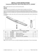
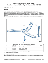
Page is loading ...

INSTALLATION INSTRUCTIONS
Centerline or Ecoline Undercounter External Caster Kit - 00-563187
These instructions are only intended for use by properly trained and qualified service technicians.
If you do not have technical training for this product, you should read the following procedure, in its entirety, to
determine if you have the necessary tools, instruments and skills required to perform the procedure. Procedures for
which you do not have the necessary tools, instruments and skills should be performed by a trained Hobart Service
technician.
The reproduction, transfer, sale or other use of this manual, without the express written consent of Hobart Service,
is prohibited.
NOTE: When installing casters, make sure the power cord strain reliefs are being utilized in the service connection,
located in the back lower left side of the unit. Also use the strain relief on the back of the machine.
Immediately after unpacking, check for possible shipping damage. If damage is found, save packing material and
contact the carrier within 15 days of delivery.
KIT # 00-563187 CENTERLINE or ECOLINE DOOR TYPE EXTERNAL CASTER KIT
Reference No. Part No. Description Qty
1 00-563191-00002 Caster, Assy, External, Left 1
2 00-563191-00001 Caster, Assy, External, Right 1
SC-118-33 Screw, Cap, Met M8 X 1.25 X 20mm SST 4
WL-019-74 Washer, Lock, Helical M8 4
F45859 Instructions 1
Fig. 1
© HOBART SERVICE 2022 Page 1 of 3 F45859 Rev. A (September 2022)

WARNING
Disconnect the electrical power to the machine and follow lockout / tagout procedures.
INSTALLATION
1. Measure amount of clearance on both sides of dishwasher. There must be a minimum of 3" clearance on both
sides of the dishwasher.
2. Position dishwasher so left and right sides are accessible.
3. Raise one side of machine and place a 2x4 under unit for support (1, Fig. 2).
Fig. 2
4. Remove adjustable feet (2, Fig. 2) from machine.
5. Using supplied hardware, mount caster assembly in adjustable feet holes.
NOTE: Ensure brake is oriented towards front of unit (See: Fig. 3).
Fig. 3
6. Carefully remove 2x4 and lower machine.
7. Repeat steps for caster assembly on other side.
8. Check for proper operation.
F45859 Rev. A (September 2022) Page 2 of 3

HEIGHT ADJUSTMENT
1. Adjust caster height until machine is level left-to-right and front-to-back.
A. Tighten caster nut to raise (Fig. 4).
B. Loosen caster nut to lower.
Fig. 4
BRAKES
1. To engage brakes, lift lever (1, Fig. 5) and pull towards front of unit until fully engaged.
2. To disengage brakes, push lever towards back of unit until fully disengaged (2, Fig. 5).
Fig. 5
Page 3 of 3 F45859 Rev. A (September 2022)
/


