Legrand 5500 Series Large Capacity Raceway Installation guide

Category
Wall & ceiling mounts accessories
Type
Installation guide
6
11
/16"
A
8.142 Sq. In
1
3
/4"
5500 Series Surface
Nonmetallic Raceway System
Installation Instruction
Wiremold Electrical Systems conform to and should be installed and properly
grounded in compliance with requirements of the current National Electrical
Code, Canadian Electrical Code or codes administered by local authorities.
All electrical products may represent possible shock or fire hazard if improperly
installed or used. Wiremold electrical products are UL listed, made for interior
use only and should be installed in conformance with current local and/or the
National Electrical Code.
5514A
Use this Fitting to back feed from an existing wall box, or to feed from
1
/2",
3
/4", and 1 inch conduit; score K.O with knife, then punch out.
5515
Punch out appropriate hole in the Tee Fitting Base, and snap to Raceway
Base; screw down to wall. Assemble Raceway covers to Base and then
snap on Tee cover overlapping R/W covers.
Punch out appropriate hole in base and snap to raceway base: screw down
to wall. The 5574 is used to feed 400, 800, 2300 raceways. Remove proper
twistout by first scoring with knife and then twisting. The 5574A is used to
feed 5400 Series Raceway. Assemble raceway covers to base and then
snap on the 5574 or 5574A cover overlapping the raceway covers.
5511
Mount flat elbow as shown; Assemble Raceway covers first, Then elbow
cover.
Communications and Signal Capacity
B
D
B
B
2.643
Sq. In
2.643
Sq. In
2.643
Sq. In
C
B
D
I
J
H
F
40614 896©1996 The Wiremold Company
The Wiremold Company
60 Woodlawn Street, P.O.Box 332500
West Hartford, CT 06110-2500
Tel (860) 233-6251 Fax 860-232-2062
2.643
Sq. In.
5.286
Sq. In.
5574
5574A
Cable Type Category/Designation Typical 20% Fill 20% Fill Undivided
O.D. (in.) A B C A B C 20% 40%
Unshielded 4-pair, 24 AWG Cat 5 UTP 0.22 42 13 28 85 27 56 42 85
Twisted Pair 4-pair, 24 AWG Cat 3 UTP 0.19 57 18 38 114 37 76 57 114
Telephone 2-pair, 24 AWG 0.14 105 34 70 211 68 140 105 211
3-pair, 24 AWG 0.15 92 29 61 184 59 122 92 184
4-pair, 24 AWG 0.19 57 18 38 114 37 76 57 114
25-pair, 24 AWG 0.41 12 4 8 24 8 16 12 24
Coaxial RG58/U 0.195 54 17 36 109 35 72 54 109
RG59/U 0.242 35 11 23 70 22 46 35 70
RG62/U 0.242 35 11 23 70 22 46 35 70
RG6/U 0.27 28 9 18 56 18 37 28 56
Twinaxial 100 Ohm 0.33 19 6 12 38 12 25 19 38
Shielded Type 1 0.39 13 4 9 27 8 18 13 27
Twisted Pair Type 2 0.465 9 3 6 19 6 12 9 19
(STP) Type 3 0.245 34 11 22 69 22 45 34 69
Fiber Optic Two Stranded (Duplex)
Multimode, 62.5/125 um 0.19 57 18 38 114 37 76 57 114
Wire Capacity 5500 Raceway
Wire Size THHN, THWN A B C D
Power Wiring 6 AWG 41 12 12 24
without Devices 8 AWG 60 13 13 28
10 AWG 72 35 35 59
12 AWG 65 33 33 63
14 AWG 55 41 41 54
Power Wiring 6 AWG 41 6 6 24
with Devices 8 AWG 60 8 8 28
10 AWG 72 16 16 54
12 AWG 65 26 26 63
14 AWG 55 34 34 54
Wire capacity is reduced to allow for proper conductor bend radius and maximum per-
missible heat rise.
1. A, B, C, D are areas of usage.
2. No one compartment may exceed capacity as specified in area B and C.
3. Total raceway max. wire capacity may not exceed fill as specified in area A or B,
depending on configuration being used.
B
D
C
5507A
Used to install devices offset from the raceway to maintain the large wire
fill capacity. Install bracket to R/W base first, mount to the wall with
screws, and mount device; after installing R/W cover, snap box cover to
bracket and finally assemble device plate.
5507A4 (not shown)
Used to install multiple devices, up to four, at one point of service. Use
same procedure to install as 5507A, above.
5507S Spacer (not Shown)
The Spacer is needed when a commercially available standard device face
plate needs to be used with the 5507A or 5507A4 device brackets; insert
the spacer into the rectangular opening of the 5507A cover; place device
onto spacer and fasten. Install face plate.
The 5510 end cap may be used as a blank to cap off the raceway or to feed
wires from a 1/2" KO. The end cap is mounted to the wall using appropri-
ate screws. Slide raceway cover under the upper lip of the end cap as
shown before snapping to base.
The 5510D is used to feed 3/4" to 2" trade size KOs from the end and
back. Line up base of fitting with the raceway base using tongues. Fasten
to wall using appropriate screws. Remove the proper KO and attach con-
duit fitting. Slide dividers into mounting guides if needed. Snap the race-
way cover to the base. Snap 5510D cover onto the base overlapping race-
way cover.
5506
Slide the 5506 seam cover on the uninstalled section of raceway cover as
shown; snap cover to the base overlapping the seam cover over the
installed section.
Mount raceway base to wall by using appropriate screws. Use 2 every 18 inches,
using the RIBS on the outermost compartments of the raceway as guides.
Snap 5500D dividers in 5500B to configure compartments as desired. Integral
dividers of the 5500BD May be removed by tearing off at the score mark. The
5500D may also be installed in the 5500BD base, if a divider needs to be replaced.
Helpful hints: 1) For mounting the raceway base, snap a chalkline on the wall which
indicates the top of the raceway. Line up the top of one end of raceway base and
screw down to the wall. Then progressively install screws at every 18 inch interval,
starting from the screwed down end while lining up the top of the raceway base with
the chalkline. Alternatively, you may use a level instead of a chalkline to ensure that
the raceway is straight. 2) Make sure the cover and base seams do not line up. The
cover should overlap the base seam by a minimum of 6 inches.
Place the 5500WC Wire clips in base as shown to contain the wires in
place while installing.
5507
Sequence for installing devices:
1. Snap bracket in raceway base.
2. Fasten devices to bracket (RJ's and other
communication devices snap to the device
plates, provided).
3. Snap Raceway covers to Base, butting
against bracket.
4. Snap trim ring into base.
5. Assemble device plates.
Use blank plates to cover any unused slots in bracket.
Note: To disassemble trim ring and base, use a
screwdriver in the screwdriver slots to pry trim ring
away from base.
5517 5518
Install one corner base first, then measure to other corner (measure from edges of fittings). Mount raceway base, and cover; assemble fitting
cover last.
A
D
E G
K
B
A
C
L
5500B
5500D
5500BD
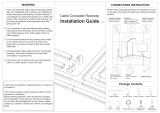
Typical Installation Layout
5500C
5510D
5510
F
G
I
L
J
K
H
B
E
5500WC
Screwdriver
slots
Screwdriver
slots
  • Page 1 1
  • Page 2 2

Legrand 5500 Series Large Capacity Raceway Installation guide

Category
Wall & ceiling mounts accessories
Type
Installation guide

Ask a question and I''ll find the answer in the document

Finding information in a document is now easier with AI