Smith & Nephew JOURNEY II BCS User manual

Type
User manual

This manual is also suitable for

Surgical Technique for use with the
JOURNEY™ II BCS and JOURNEY™ II CR
2
NAVIO Surgical System
Surgical Technique for use with the JOURNEY™ II BCS and JOURNEY II CR
Smith & Nephew


The following technique is for informational and educational purposes only. It is not intended

the appropriate products and techniques according to their own clinical judgment for each of


the Instructions for Use packaged with the product.


3
Introduction

recommended surgical technique for using the
NAVIO™ surgical system technology with the JOUR
NEY™ II CR (Cruciate Retaining) and JOURNEY™ II



the NAVIO system.




the NAVIO surgical system. Additional information
on the JOURNEY II CR (Cruciate Retaining) and BCS




& Nephew.
4
Contents
........ 5
Design Rational/Surgical Planning Rational........... 6
 ......................... 7
 .......................................... 8
Positioning the System .......................................... 9
1. System and Patient Setup .................................. 10
2. Bone Tracking Hardware ................................... 12
3. Surgical Preferences .......................................... 14
4. Registration ....................................................... 17
5. Ligament Balancing ........................................... 25
6. Implant Planning ................................................ 26
 .......... 32
8. Bone Cutting ..................................................... 36
9. Trial Reduction ................................................... 44
10. Cement and Close .......................................... 45
 ............................ 46
Notes ..................................................................... 47
 ........................ 48
5
Intended Use
The NAVIO surgical system is intended to assist the surgeon in

reference information to anatomical structures during orthopedic
procedures.
Indications for Use
The NAVIO™ surgical system is indicated for use in surgical knee





The NAVIO surgical system is indicated for use with cemented
implants only.
Contraindications





knee replacement surgery.


Warning: 
instructions for use and recommendations for the

6






through the unique features of the JOURNEY





unicompartmental replacement. This system is
designed for use in patients in primary total knee

posterior cruciate ligaments are incompetent and
the collateral ligaments remain intact.


compartment than other total knee systems.



whether additional implant constraint is more
appropriate.
Surgical Planning Rationale
Co
Surgical Technique for more details on the
surgical planning rationale for the implant
components.
Figure 1
7





The optical tracking camera communicates the



the handpiece (Figure 2).






placement plan.


guide is separated into sequential sections:
1. System and Patient Setup
2. Bone Tracking Hardware
3. Surgical Preferences
4. Registration
5. Ligament Balancing
6. Implant Planning

8. Bone Cutting
9. Trial Reduction
10. Cementing Final Components & Closing



Preferences section (Section 3) of this guide.
Figure 2
8

NAVIO™ Instrument tray












or dropped tool.
Femur Cut Adapter
JOURNEY™









Figure 3b.



Handpiece Tracker Frame
Tracker Clamps (2)

Anspach Surgical Drill


Rasp
Femur Tracker Frame
Tissue Protector

Handpiece
Long Attachment
Figure 3a.

tray that contains the required instrumentation





surfaces (Figure 3a).
9
Positioning the System
Position the NAVIO™ computer cart so that the
surgeon can clearly see and easily operate the
graphical user interface at all times. The computer






the laser pointer integrated into the faceplate of the



during the operation to meet the needs of the

center.

the Camera Orientation Adjustment screen of the

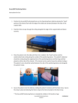
Once the system is positioned and the patient has



drape manufacturer (Figure 5). An additional





Left-knee OR Setup (above)
Right-knee OR Setup (above)
Figure 4a.
Additional Notes








to the entire tracker frame.




Figure 4b.
10
Preparing the System and Tool



NAVIO™ Surgical System for Total Knee Arthroplasty
Users Manual)







consists of the following:
5 mm Spherical Bur


touchscreen monitor with a sterile drape. This will
allow the surgeon to manipulate the touchscreen



included instructions for use for how to properly
apply to the monitor).
Patient Setup



patient registration.







Figure 6.
Figure 5.
1 System and Patient Setup
11

and inspect the joint. If any prominent spurs or



the leg motion.

typically found on the lateral aspect of the medial





interfere with the collateral ligaments and capsule. In






patellar osteophytes.





component implantation.


arthroplasty.


instructions for use and product documentation.
1 System and Patient Setup
12
Figure 8.
Placing Tracking Hardware







towards the optical tracking camera so the markers






9.)



Use the tissue protector to mark the position of the


the tissue protector to ensure the pins are placed
parallel to each other.




to place the clamp touching the skin.



(Figure 9). Orient the spheres towards the camera
and slide the array away from the incision site.
Femur Tracker Array Placement


in the center of the femur (Figure 9).





pins are placed parallel to each other.
Figure 7.
Figure 9.
2 Bone Tracking Hardware
Femur Tracker Frame

13
Slide the tracker clamp (with the clamp opening



clamp where it is touching the patient's skin.
Clamp the femur tracker frame
. Place the smaller side
of the tracker frame
Orient the spheres towards the camera and slide
the array away from the incision site.

Prior to registering the leg with the NAVIO™

of the optical tracking camera and tracker frames

registration and cutting processes.



following two positions:




 Both



(Figure 11).
Figure 10. 
Figure 11. 
2 Bone Tracking Hardware
14








performed.




Femur First
1. 

2. Femur Component Placement

3. 

4. 

5. 

Tibia First
1. 
Section 6)
2. 
Section 8)
3. 
Section 5)
4. Femur Component Placement
Section 6)
5. 
Section 7)
6. Femur Bone Preparation
Section 8)
Figure 13.
Figure 12.
3 Surgical Preferences
15
Rotational References

to choose landmark collection preferences on the



is calculated.


the component on the femur (Figure 14a):
1. 
2. 
3. Posterior Condylar



1. 
2. 
3. 
4. 
Based on the chosen preference for rotational

registration of the patient anatomy. Further details



Figure 14a.
Figure 14b.
3 Surgical Preferences
16
Joint Line Selection Preference

which allows the user to choose a landmark



This reference line is then displayed during the

placement.
Checkpoint Pins




stages throughout the procedure to determine if

Figure 16.
3 Surgical Preferences
Figure 15.
Figure 17.
Warning: Ensure that the checkpoint pins


dislocating the checkpoint pins.
17




and kinematics. The user may choose to

the included NAVIO system footpedal or the
touchscreen controls. Any collected point


Femur Neutral Position






right footpedal to collect the position (Figure




Hip Center
The Hip Center Calculation stage will follow
the femoral tracker array through circular




error.



wide circle. Slowly rotate the leg at the hip until

(Figure 19).



Figure 18.
Figure 19.
4 Registration
18
Figure 20.
Ankle Center


the most prominent portion (Figure 20). Ensure





Femoral Condyle
There are four femoral landmark points to collect.

during Implant Planning (Section 6). It is important
to take care to understand where these points




Knee Center





Most Posterior Medial Point



This point is used in conjunction with the anterior
notch point and the most posterior lateral point for

Figure 22.
Figure 21.
4 Registration
19
Figure 23.
Figure 24.
Figure 25.
Most Posterior Lateral Point
This point is used in conjunction with the anterior
notch point and the most posterior medial point for

Anterior Notch Point
This point is used as a reference during

of the implant component.
Femoral Condyle Surface Mapping



well as the four discrete femur landmark points




down the footpedal. The user must input enough
information into the system to appropriately



map input in 3D.
4 Registration
20
Femoral Condyle Rotational References

options on which the femur rotational reference

are used during Implant Planning (Section 6) for
component placement onto the patient anatomy. It
is important to understand how these collections



Transepicondylar Axis Collection
If the epicondyles are selected as the preference





stage.
Femoral AP Axis Collection









Figure 26.
Figure 27.
4 Registration
  • Page 1 1
  • Page 2 2
  • Page 3 3
  • Page 4 4
  • Page 5 5
  • Page 6 6
  • Page 7 7
  • Page 8 8
  • Page 9 9
  • Page 10 10
  • Page 11 11
  • Page 12 12
  • Page 13 13
  • Page 14 14
  • Page 15 15
  • Page 16 16
  • Page 17 17
  • Page 18 18
  • Page 19 19
  • Page 20 20
  • Page 21 21
  • Page 22 22
  • Page 23 23
  • Page 24 24
  • Page 25 25
  • Page 26 26
  • Page 27 27
  • Page 28 28
  • Page 29 29
  • Page 30 30
  • Page 31 31
  • Page 32 32
  • Page 33 33
  • Page 34 34
  • Page 35 35
  • Page 36 36
  • Page 37 37
  • Page 38 38
  • Page 39 39
  • Page 40 40
  • Page 41 41
  • Page 42 42
  • Page 43 43
  • Page 44 44
  • Page 45 45
  • Page 46 46
  • Page 47 47
  • Page 48 48

Smith & Nephew JOURNEY II BCS User manual

Type
User manual
This manual is also suitable for

Ask a question and I''ll find the answer in the document

Finding information in a document is now easier with AI