Page is loading ...

univation
™
X
Unicondylar Knee System Surgical Technique
Aesculap Orthopaedics

2
univation
™
X Unicondylar Knee System
Surgical Technique
Table of Contents
I. System Overview ......................................................3
II. Indications, Contraindications, Warnings and Potential Risks & Precautions .....4
III. Preoperative Planning ..................................................6
IV. Approach ............................................................7
V. Instrument Assembly Instructions ........................................8
1. Extramedullar Tibial Alignment ........................................8
2. Femur Trial Insertion Instrument .......................................9
VI. Workow Synopsis ...................................................10
VII. Surgical Technique ...................................................11
1. Tibia Alignment ....................................................11
2. Tibia Resection ....................................................13
3. Measuring Flexion and Extension Gaps .................................14
4. Femur Preparation ..................................................16
a. Distal Cut .......................................................18
b. Chamfer and Posterior Cuts .........................................18
5. Tibia Sizing and Preparation ..........................................20
6. Implant Sizing and Final Preparation ..................................24
7. Trial Reduction and Implant Final Components ..........................26
8. Trial and Final Implant ..............................................28
9. Cementing Technique ...............................................29
10. Closure ..........................................................29
VIII. Implants Overview ....................................................30
IX. Femur/Tibia Compatibility .............................................30
X. Instrument Overview ..................................................30
Saw Blades ..........................................................35
Table of Contents

3
The univation™ X Unicondylar Knee System was designed with a xed platform to treat
medial knee defects. The system oers streamlined, user-friendly instrumentation
to optimize surgical time and allow for intra-operative exibility. The univation X
system is an enhanced design with ecient instrumentation to help restore natural
knee kinematics.
Design Advantages:
■
Advanced Surface Technology: All univation X knee components are created
with the 7-layer Advanced Surface technology, which makes the system the rst
choice for surgeons and patients alike.
■
Anatomic Implant Fit and Design: With 5 femoral sizes and 6 tibial sizes there are
over 30 possible implant combinations. The design of each component addresses
the various needs of the natural anatomy of the patient while providing optimal
bone coverage and minimal bone resection.
■
Gap Balancing Technique: Aesculap’s innovative gap balancing instrumentation
allows the surgeon to manage the gap before the distal cut is made. The
instrumentation and technique also permits gap management by resecting the
posterior condyles as well.
■
Stability and Bone Preservation: univation X is a xed platform with a peg
design that oers optimal primary stability with minimal cuts to preserve bone.
There are three sizes that have identical cuts allowing the surgeon intra-operative
exibility.
■
IQ Instrumentation Platform: Instrumentation is part of the Intuitive & Quick (IQ)
platform, which is designed to create eciency in the operating room (OR) through
a streamlined workow, improved ergonomics and familiar instrumentation, all
with reproducible results. This is accomplished through:
Reduced instrumentation
Ergonomic handles
Fast-acting lock mechanisms
Color-coded instruments and trays
■
Ecient Reprocessing: univation X IQ instruments are stored in modern and
simple wash trays for eciencies in reprocessing. Instruments can remain in the
tray during cleaning for fast sterilization intended to save time and money in the
Central Sterile Supply Department (CSSD). Note: Complex instruments such as
incision guides require manual precleaning.
I. System Overview

4
univation
™
X Unicondylar Knee System
Surgical Technique
Indications for Use
The univation X Unicompartmental Knee System is indicated for cemented use only in patients undergoing surgery for a severely
painful and/or disabled joint damaged as a result of osteoarthritis, traumatic arthritis, or a failed previous implant when only one
condyle of the knee (medial) is aected.
Contraindications
Contraindications include, but are not limited to:
■
Presence of fever, infection or inammation (systemic or localized);
■
Morbid obesity;
■
Pregnancy;
■
Mental illness or drug abuse
■
Severe osteopenia (or any medical or surgical condition) which would preclude potential benets of implants;
■
Suspected or documented metal allergy or intolerance;
■
Mixing of implant components from other manufacturers;
■
Any case not listed in the indications; and
■
Patients unwilling or unable to follow post-operative care instructions.
Warnings
■
The univation X implants are designed for single patient use only and must never be reused. As with all other orthopedic
implants, the univation X components should never be re-implanted under any circumstances.
■
The mixing of dierent manufacturer implant components is not recommended due to metallurgical, mechanical and functional
reasons. Dissimilar metals in contact with each other can accelerate the corrosion process due to galvanic corrosion eects. Do
not use implants or instruments from other systems or manufacturers, and do not mix cobalt-chromium and titanium implant
components together in a total knee system.
■
The univation X implants can become loose or break if subjected to increased loading. Factors such as the patient’s weight,
activity level and adherence to weight-bearing or load-bearing instructions can aect the implant’s longevity. Damage to the
weight-bearing bone cement and/or bone structures caused by infection can give rise to loosening of the components and/or
fracture of the bone.
■
The univation X Unicompartmental Knee System has not been evaluated for safety and compatibility in the MR environment. The
univation X Unicompartmental Knee System implants have not been tested for heating or migration in the MR environment.
■
These warnings do not include all adverse eects which could occur with surgery, but are important considerations specic
to metallic devices. The risks associated with orthopedic surgery, general surgery and the use of general anesthesia should be
explained to the patient prior to surgery. See the complete indications for use provided with the product.
II. Indications, Contraindications, Warnings and Potential Risks & Precautions

5
Precautions
■
The univation
™
X Unicompartmental Knee System is intended to be used by surgeons specializing in orthopedic surgery who have
a thorough knowledge of knee arthroplasty, joint morphology and the biomechanical principles of the knee.
■
Pre-operative assessment of the suitability of the patient’s anatomy for accepting implants is made on the basis of X-rays, CT
scans and other radiological studies.
■
Only patients that meet the criteria described in the Indications for Use section should be selected.
■
Correct selection of the implant is extremely important. The morbidity as well as patient weight height, occupation and/or
degree of physical activity should be considered.
■
Proper implant handling before and during the operation is crucial. Handle the implant components properly. Ensure
packaging integrity for implant sterility. Do not use any implant where the packaging has been breached. Do not resterilize an
implant. Do not allow the implants surfaces to be damaged.
■
Adequately instruct the patient. The physician should inform the patient about knee implant advantages and disadvantages,
post-operative limitations, weight/load bearing stresses which could aect bone healing, implant limitations, and the fact that
premature physical activity and full weight/load bearing stresses have been implicated in premature loosening, damage and/or
fracture of knee prosthesis.
II. Indications, Contraindications, Warnings and Potential Risks & Precautions (continued)

6
univation
™
X Unicondylar Knee System
Surgical Technique
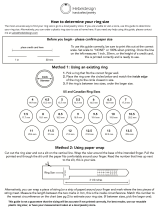
For every knee arthroplasty, careful pre-operative X-ray
planning is recommended.
The size of the femoral component is determined in the
X-ray before the surgery. To do this, X-ray templates are
available in dierent scales.
The contours of the implant partly project up to 2 mm over
the bony edge and therefore replace the cartilage.
The tibial component should also be determined, but the
size of the tibia can easily be determined intra-operatively.
The tibial slope of the tibial component should correspond
as closely as possible to the natural slope of the patient. For
this reason, it is also determined from the X-ray image.
The following images are required for X-ray analysis:
■
Knee joint in AP projection (Fig. 1)
■
Knee extended
■
Centered over the distal patella
■
Knee joint in lateral projection (Fig. 2)
■
Knee 30° exed
■
Centered over the distal patella.
■
Ideally for tibial slope: long leg image in lateral
projection.
The results of preoperative planning should be documented
in the patients le and available during the operative
procedure for reference.
Fig. 2
Fig. 1
III. Preoperative Planning
Note: Place the dotted line of the femoral template in
parallel to the longitudinal axis of the femur. The femoral
templates are designed so that the dotted line is parallel
to the lengthwise axis of the femur. Please note that the
femoral pegs do not run parallel to the longitudinal axis.
The posterior edge of the implant should not project over
the posterior edge of the condyle.

7
IV. Approach
At 90° exion, make a paramedial skin incision from the
medial edge of the patella to a point 2 to 3 cm distal of the
joint line. (Fig. 3) The incision point descends through the
joint capsule. At its cranial end, extend the capsule incision
about 1 to 2 cm tilted from the medial into the musculus
vastus medialis. For a better view, remove part of the
retropatellar fat pad (Hoa’s fat pad). The surgeon should
decide the overall length of the incision based on each
patient and what is required for proper visualization of the
knee anatomy.
All osteophytes must be removed from the medial edge
of the medial condyle as well as from the intercondylar
notch and in the posterolateral area of the medial condyle.
Dierent exion positions of the leg can be used to reveal
all the remaining osteophytes through the moving incision
window.
Fig. 4
Fig. 3
Caution: Careful consideration must be made to not
damage the suprapatellaris recess/bursa
Medial parapatellar Arthrotomy
With the knee in exion or extension, the arthrotomy is
performed starting proximal to the superior pole of the
patella, incising the rectus femoris tendon longitudinally.
(Fig. 4) Continuing the arthrotomy distally around the
medial aspect of the patella, and ending medial to the tibial
tubercule is then carried out.

8
univation
™
X Unicondylar Knee System
Surgical Technique
■
Press and hold the button on the
bimalleolar clamp.
■
Guide the holder for the
bimalleolar clamp into the groove.
■
After the neutral position has been
reached, release the button.
■
Turn the wheel on the tibial
alignment handle to the open
position, in which it shows 'OPEN'.
■
Place the handle onto the holder
for the bimalleolar clamp.
■
Adjust to the neutral position.
■
Press and hold the handle
adjustment wheel to release the
locking mechanism.
■
Insert the holding rod for the
resection block into the handle.
■
After reaching the desired height,
release the wheel.
■
Turning the wheel will allow a ne
adjustment to the height.
1 2 3
■
Connect the support rod to the
right or left tibial resection block.
■
Lock the assembly using the front
wheel.
■
Insert the rod into the sleeve and
tighten the xation screw.
4 5
V. Instrument Assembly Instructions
1. Extramedullar Tibial Alignment

9
1
2
3
■
Insert the implant holder with
the thread into the sleeve of the
femoral holder.
■
Place the insertion instrument
with both pins parallel to the trial
implant. Place rm pressure on
the implant and click it into place.
■
The femoral trial holder is xated
to the trial using a rolling motion.
Using rm pressure, start with the
lower pin and roll upward.
■
Tighten the holder onto the
femoral trial.
2. Femur Trial Holder Instrument

10
univation
™
X Unicondylar Knee System
Surgical Technique
VI. Workow Synopsis
1
2
3
4 5
6
7 8
1. Tibial alignment and proximal tibia
resection
2. Measuring exion and extension gaps
3. Femur preparation
4. Femur anterior and posterior cuts
5. Tibia sizing
6. Implant sizing and nal preparation
7. Trial reduction and implant nal
components
8. Trial and nal implant

11
Fig. 6
Fig. 5
VII. Surgical Technique
1. Tibia Alignment
Extramedullary Alignment
■
The extramedullary (EM) alignment system assembly is
placed parallel to the front of the tibia with the leg in
exion.
■
The bimalleolar clamp, previously placed in the neutral
position, is xed around the lower leg just above and
centered around the ankle joint.
Height Adjustment
■
Using the cutting check plate, the height and posterior
slope of the resection can be checked.
■
If necessary, the resection height can be adjusted using
the wheel for the height adjustment. The goal is to
remove any defect of the tibial plateau so that the tibial
implant lays on intact bone for optimal implant support.
■
Depending on the resection method, either through the
sawing slit or on the block, the resection height must be
appropriately adjusted.
A: Bimalleolar clamp NS345R, B: Holder for bimalleolar clamp NS344R, C: Tibial alignment system NS342R, D: Holding rod for tibial resection block
NM583R, E: Tibial resection block right/left NM585R/NM584R, F: Cutting depth check plate NS850R
A B C D E F
Note: When aligning it parallel to the axis of the tibia
(2 and 3 nger rule), a tibial slope of 5° is pre-adjusted.

12
univation
™
X Unicondylar Knee System
Surgical Technique
1. Tibia Alignment (continued)
Varus-valgus Alignment
■
Push the knob (1) on the bimalleolar clamp and slide
the alignment system medially or laterally to adjust the
varus/valgus of the proximal tibial resection. The distance
between the laser-marked lines on the scale corresponds
to a deviation of 1° for a tibia length of 40 cm.
Alignment of the tibial slope
■
Releasing the xation wheel (2) on the lower part of
the alignment system (by turning the screw to OPEN)
allows the alignment system to be shifted in the anterior
direction to increase the slope of the proximal tibial
resection. The distance between the laser-marked lines
on the scale corresponds to a deviation of 1° for a tibia
length of 40 cm.
Fig. 8
Fig. 7
1
2
A: Bimalleolar clamp NS345R, B: Holder for bimalleolar clamp NS344R, C: Tibial alignment system NS342R,
D: Holding rod for tibial resection block NM583R, E: Tibial resection block right/left NM585R/NM584R
A B C D
E
■
Fasten the tibial cutting guide with two headless pins
through the two lowest marked pinholes to the bone. To
secure the resection block, a third pin can be inserted in
the convergent pin holes.

13
2. Tibia Resection
Step 1:
■
The horizontal tibia cut is made either through the
cutting guide (Fig. 9) or on top of the cutting guide
(Fig. 10). In either approach ensure the blade reaches the
back of the joint.
Step 2:
■
Using the reciprocating saw blade, make the vertical
tibial cut. The cut should be made slightly medial to the
origin of the anterior cruciate ligament.
■
Point the saw blade towards the femoral head in the
direction of the femoral axis as shown in (Fig. 11).
Fig. 10
Fig. 9
A: Headless pins 63 mm NP583R, B: Pin driver NP613R, C: Acculan
®
drill, D: Acculan saw, E: Acculan reciprocating saw
A B DC E
Note: The dierence in height from the top of the
cutting guide to the cutting guide slot is 4 mm.
Caution: The protection of the
surrounding soft tissue of the
knee joint is critical. Special
attention and necessary retractor
instruments should be used to
protect this during the tibia
resection.
Fig. 11
■
Tip: The vertical/sagittal cut should
not extend below the transverse/
horizontal cut.
■
You can now use the necessary
instrumentation to excise the
resected tibial plateau.

14
univation
™
X Unicondylar Knee System
Surgical Technique
3. Measuring Flexion and Extension Gaps
Measurement with Spacers
■
The exion gap is measured with the spacers. Please note
that the exion gap is measured with the leg hanging. To
do this, an assistant must lift the upper thigh slightly. The
thickness of the spacer is correct if it can no longer be
shifted and pushed in and out while holding it with two
ngers.
Fig. 12
Fig. 13
A: Trial Spacer NM651R – NM653R, B: Gap distractor for femoral-tibial distractor NP609R, C: Femoral alignment guide NP894R
A B C
■
The minimum height for the tibial plateau and meniscus
component is 7 mm. If the 7 mm spacer does not t, the
tibia must be resected again.
Caution: Before extending the leg for measurement of
the extension gap, remove the spacer to avoid injury to
the ligaments.
Optional: Instead of the spacer, a distractor can be used to
measure the gaps. To do this, use the spreader in exion and
extension and apply the same force. The size of the gap can
be read o the instrument.
Note: In some cases, the cement thickness causes the
meniscus components to be inserted about 1 mm higher
than planned. Therefore, it is recommended that the joint
gap is resected to at least 8 mm.

15
■
Flexion and extension gaps must be balanced for optimal
post-operative results.
■
The resection height can be adjusted either through the
distal cut (distal cutting block) or through the posterior/
chamfer cut (2-in-1 cutting block), by setting the blocks
to the corresponding level on the spacer. At “0”, the gaps
are not changed. At +1, +2, the cut is increased. At -1,
-2, the cut is decreased.
Gap Balancing Strategies
Scenario Option 1 Option 2
Flexion Gap
= Extension
Gap
Both resection blocks
are set to ‘0’. The
implant thickness is
resected.
Extension
Gap >
Flexion Gap
The extension gap
is adjusted to the
exion gap. There is
less resection in the
distal cut. The distal
cutting guide is set at
-1 or -2.
The exion gap
is adjusted to the
extension gap.
There is more
resection in the
posterior cut
(2-in-1 cutting
guide). The
2-in-1 cutting
block is set to
+1 or +2.
Extension
Gap <
Flexion Gap
The extension gap is
adjusted to the exion
gap. There is greater
resection distally than
posteriorly. Cutting
block is set to +1 or
+2.
On the 2-in-1
cutting guide,
that is the
posterior cut,
no less can be
resected.
Fig. 15
Fig. 14
A: Distal cutting guide NM540R, B: Femur 2-in-1 cutting guide left/right NM006R – NM011R
A B

16
univation
™
X Unicondylar Knee System
Surgical Technique
4. Femur Preparation
a. Distal Femur Cut
■
Place the distal femur cutting guide onto the trial spacer
with the leg placed in extension.
■
For alignment to the mechanical axis, the rod and
the adapter are attached to the spacer. The rod points
towards the femoral head.
Fig. 17
Fig. 16
A B C
A: Trial Spacer NM651R – NM653R, B: Distal femur cutting guide NM540R, C: Femoral alignment guide NM560R,
D: Alignment check rod with sleeve NE331R, E: Alignment check rod NP471R
ED
■
Fasten the cutting guide with two headless pins. Be sure
that the cutting guide is in contact with the distal and
anterior condyle.
Note: The distal cutting guide should slide easily along
the spacer tool.

17
■
Before resection, remove the spacer and bring the knee
to 90° exion.
Fig. 19
Fig. 18
A B C
D
E F
A: Headless pins 63 mm NP583R, B: Pin driver NP613R, C: Acculan
®
drill, D: Tibial preparation plateau T1-T6 NM591R – NM596R,
E: Acculan reciprocating saw, F: Femoral size determination guide NM667R
Caution: The tibial plateau must be protected during
resection using the tibia preparation plate.
Femoral Sizing
■
It is recommended to measure the femur size on the
X-ray. The posterior part is dicult to assess
intra-operatively. The femur sizer is used to determine
the size of the femur component.
■
Place the femoral sizer onto the spacer with the side
marked “F” for xed version (facing outward). The sizer is
placed onto the previously planned level of the spacer.
■
The femur sizing instrument measures the anterior
section of the femoral component shield. The distal
resection should also be covered as much as possible.
Note: The spacer contains ridges on the side which
corresponds to the femoral size. The sizer should be
placed at “0” and slide forward. Careful attention should
be made to ensure the femoral size guide is placed on the
same groove on both sides of the spacer.
Note: Please make sure you can read “F” on the femoral
sizer.

18
univation
™
X Unicondylar Knee System
Surgical Technique
Fig. 20
4. Femur Preparation (continued)
b. Femur Chamfer and Posterior Cuts
■
Place the 2-in-1 cutting guide onto the spacer with the
knee in 90° exion.
■
The 2-in-1 cutting guide is placed ush against the distal
surface and posterior condyle.
Fig. 21
A: Trial Spacer NM651R – NM653R, B: Femur 2-in-1 cutting guide left/right NM006R – NM011R
A B
■
Based on the tibia cut, the rotation of the femur is
adjusted. In the case of a medial or lateral overhang of
the cutting guide, translation in the medial/lateral plane
can be adjusted.
Note: Protection of the surrounding soft tissue of the
knee joint is imperative! We recommend the use of
Hohmann or collateral retractors for protection.

19
■
The resection block is fastened with two headed pins. The
anterior pin is 30 mm long (NP585R), and the posterior
pin is 50 mm long (NP586R).
Fig. 23
Fig. 22
A: Headed pins 30 mm NP585R, B: Headed pin 50 mm NP586R, C: Pin driver NP613R, D: Acculan
®
drill, E: Tibial preparation plateau
T1-T6 NM591R – NM596R, F: Acculan saw
A
B C FD
■
Make the posterior cut rst, then the chamfer cut is
made.
Note: Either the trial spacer or tibia preparation plateau
should be used to protect the tibia.
E

20
univation
™
X Unicondylar Knee System
Surgical Technique
Fig. 24
Fig. 25
5. Tibia Sizing and Preparation
■
Use the hook to measure the AP dimension of the tibia
and tibia implant size.
A: Tibial size measurement instrument AP NM903R, B: Tibial preparation plateau T1-T6 NM591R – NM596R
A B
■
Place the corresponding size tibial plate on the tibial cut.
The plate should not overhang on the sides. If necessary,
a new sagittal cut should be performed to enlarge the ML
surface. It is important during this process to keep the
footprint of the cruciate ligament intact.
1/40