Page is loading ...


i
Warnings and Cautions:
Installation Instructions
Secure Racking
If Secure Racked units are installed in a closed or multi-unit rack assembly, they may
require further evaluation by Certification Agencies. The following items must be
considered.
1. The ambient within the rack may be greater than room ambient. Installation
should be such that the amount of air flow required for safe operation is not
compromised. The maximum temperature for the equipment in this environment is
45°C. Consideration should be given to the maximum rated ambient.
2. Installation should be such that a hazardous stability condition is not achieved due
to uneven loading.
Input Supply
1. Check nameplate ratings to assure there is no overloading of supply circuits that
could have an effect on overcurrent protection and supply wiring.
2. When installing 48 VDC rated equipment, it must be installed only per the following
conditions:
A. Connect the equipment to a 48 VDC supply source that is electrically isolated
from the alternating current source. The 48 VDC source is to be connected to
a 48 VDC SELV source.
B. Input wiring to terminal block must be routed and secured in such a manner
that it is protected from damage and stress. Do not route wiring past sharp
edges or moving parts.
C. A readily accessible disconnect device, with a 3 mm minimum contact gap,
shall be incorporated in the fixed wiring.
Grounding
Reliable earthing of this equipment must be maintained. Particular attention should
be given to supply connections when connecting to power strips, rather than direct
connections to the branch circuit.
No Serviceable Parts Inside; Authorized Service Personnel Only
Do not attempt to repair or service this device yourself. Internal components must be
serviced by authorized personnel only.
• Shock Hazard - Do Not Enter
• Lithium Battery
CAUTION: Danger of explosion if battery is incorrectly replaced. Replace
only with same or equivalent type recommended by the manufacturer.
Discard used batteries according to the manufacturer's instructions.

ii
Warnings and Cautions
Disconnect Power
If any of the following events are noted, immediately disconnect the unit from the outlet
and contact qualified service personnel:
1. If the power cord becomes frayed or damaged.
2. If liquid has been spilled into the device or if the device has been exposed to rain
or water.

iii
Agency Approvals
FCC Part 15 Regulation
This equipment has been tested and found to comply with the limits for a Class A digital
device, pursuant to part 15 of the FCC Rules. These limits are designed to provide
reasonable protection against harmful interference when the equipment is operated
in a commercial environment. This equipment generates, uses, and can radiate radio
frequency energy and, if not installed and used in accordance with the instruction
manual, may cause harmful interference to radio communications. Operation of this
equipment in a residential area is likely to cause harmful interference in which case the
user will be required to correct the interference at his own expense.
This device complies with part 15 of the FCC Rules. Operation is subject to the following
two conditions: (1) This device may not cause harmful interference, and (2) this device
must accept any interference received, including interference that may cause undesired
operation
WARNING: Changes or modifications to this unit not expressly approved by
the party responsible for compliance could void the user’s authority to operate
the equipment
EMC, Safety, and R&TTE Directive Compliance
The CE mark is affixed to this product to confirm compliance with the following
European Community Directives:
• Council Directive 89/336/EEC of 3 May 1989 on the approximation of the laws
of Member States relating to electromagnetic compatibility;
and
• Council Directive 73/23/EEC of 19 February 1973 on the harmonization of
the laws of Member States relating to electrical equipment designed for use
within certain voltage limits;
and
• Council Directive 1999/5/EC of 9 March on radio equipment and
telecommunications terminal equipment and the mutual recognition of their
conformity.
Industry Canada
This Class A digital apparatus complies with Canadian ICES-003.
Cet appareil numérique de la classe A est conforme à la norme NMB-003 du Canada.
This product meets the applicable Industry Canada technical specifications
The Ringer Equivalence Number is an indication of the maximum number of devices
allowed to be connected to a telephone interface. The termination on an interface may
consist of any combination of devices subject only to the requirement that the sum of
the RENs of all the devices does not exceed five.

iv
Table of Contents
1. Introduction . . . . . . . . . . . . . . . . . . . . . . . . . . . . . . . . . . . . . . . . . . . . . . . . . . . . . . . . . . . . . 1-1
2. Unit Description . . . . . . . . . . . . . . . . . . . . . . . . . . . . . . . . . . . . . . . . . . . . . . . . . . . . . . . . . .
2-1
2.1. Front Panel . . . . . . . . . . . . . . . . . . . . . . . . . . . . . . . . . . . . . . . . . . . . . . . . . . . . . . . . . . . . 2-1
2.2. Back Panel . . . . . . . . . . . . . . . . . . . . . . . . . . . . . . . . . . . . . . . . . . . . . . . . . . . . . . . . . . . . 2-2
3. Getting Started . . . . . . . . . . . . . . . . . . . . . . . . . . . . . . . . . . . . . . . . . . . . . . . . . . . . . . . . . . 3-1
3.1. Quick Hardware Installation . . . . . . . . . . . . . . . . . . . . . . . . . . . . . . . . . . . . . . . . . . . . . . . 3-1
3.1.1. Apply Power to the RSM . . . . . . . . . . . . . . . . . . . . . . . . . . . . . . . . . . . . . . . . . . . 3-1
3.1.2. Connect your Control Device to the RSM
. . . . . . . . . . . . . . . . . . . . . . . . . . . . . 3-1
3.2. Communicating with the RSM . . . . . . . . . . . . . . . . . . . . . . . . . . . . . . . . . . . . . . . . . . . . . 3-2
4. Hardware Installation . . . . . . . . . . . . . . . . . . . . . . . . . . . . . . . . . . . . . . . . . . . . . . . . . . . . . 4-1
4.1. Connecting Power to the RSM Unit . . . . . . . . . . . . . . . . . . . . . . . . . . . . . . . . . . . . . . . . . 4-1
4.1.1. AC Powered Units . . . . . . . . . . . . . . . . . . . . . . . . . . . . . . . . . . . . . . . . . . . . . . . .
4-1
4.1.2. DC Powered Units . . . . . . . . . . . . . . . . . . . . . . . . . . . . . . . . . . . . . . . . . . . . . . . .
4-1
4.2. Connecting the Network Cable . . . . . . . . . . . . . . . . . . . . . . . . . . . . . . . . . . . . . . . . . . . . 4-2
4.3. Connecting Devices to the RSM . . . . . . . . . . . . . . . . . . . . . . . . . . . . . . . . . . . . . . . . . . . 4-2
5. Configuration . . . . . . . . . . . . . . . . . . . . . . . . . . . . . . . . . . . . . . . . . . . . . . . . . . . . . . . . . . . . 5-1
5.1. Communicating with the RSM Unit . . . . . . . . . . . . . . . . . . . . . . . . . . . . . . . . . . . . . . . . . 5-1
5.1.1. The Text Interface
. . . . . . . . . . . . . . . . . . . . . . . . . . . . . . . . . . . . . . . . . . . . . . . . 5-1
5.1.2. The Web Browser Interface . . . . . . . . . . . . . . . . . . . . . . . . . . . . . . . . . . . . . . . . .
5-3
5.2. System SetUp Ports . . . . . . . . . . . . . . . . . . . . . . . . . . . . . . . . . . . . . . . . . . . . . . . . . . . . . 5-4
5.3. Configuration Menus . . . . . . . . . . . . . . . . . . . . . . . . . . . . . . . . . . . . . . . . . . . . . . . . . . . . 5-4
5.4. Defining System Parameters . . . . . . . . . . . . . . . . . . . . . . . . . . . . . . . . . . . . . . . . . . . . . . 5-5
5.4.1. The Real Time Clock and Calendar
. . . . . . . . . . . . . . . . . . . . . . . . . . . . . . . . . . 5-7
5.4.2. The Invalid Access Lockout Feature . . . . . . . . . . . . . . . . . . . . . . . . . . . . . . . . . .
5-8
5.4.3. The Audit Log
. . . . . . . . . . . . . . . . . . . . . . . . . . . . . . . . . . . . . . . . . . . . . . . . . . . 5-9
5.4.4. Callback Security
. . . . . . . . . . . . . . . . . . . . . . . . . . . . . . . . . . . . . . . . . . . . . . . 5-10
5.5. User Accounts . . . . . . . . . . . . . . . . . . . . . . . . . . . . . . . . . . . . . . . . . . . . . . . . . . . . . . . . 5-12
5.5.1. Supervisor Access
. . . . . . . . . . . . . . . . . . . . . . . . . . . . . . . . . . . . . . . . . . . . . . 5-12
5.5.2. Port Access . . . . . . . . . . . . . . . . . . . . . . . . . . . . . . . . . . . . . . . . . . . . . . . . . . . .
5-12
5.6. Managing User Accounts . . . . . . . . . . . . . . . . . . . . . . . . . . . . . . . . . . . . . . . . . . . . . . . 5-13
5.6.1. Viewing User Accounts . . . . . . . . . . . . . . . . . . . . . . . . . . . . . . . . . . . . . . . . . . .
5-13
5.6.2. Adding User Accounts
. . . . . . . . . . . . . . . . . . . . . . . . . . . . . . . . . . . . . . . . . . . 5-14
5.6.3. Modifying User Accounts
. . . . . . . . . . . . . . . . . . . . . . . . . . . . . . . . . . . . . . . . . 5-16
5.6.4. Deleting User Accounts
. . . . . . . . . . . . . . . . . . . . . . . . . . . . . . . . . . . . . . . . . . 5-16
5.7. RS232 Port Configuration . . . . . . . . . . . . . . . . . . . . . . . . . . . . . . . . . . . . . . . . . . . . . . . 5-17
5.7.1. RS232 Port Modes
. . . . . . . . . . . . . . . . . . . . . . . . . . . . . . . . . . . . . . . . . . . . . . 5-17
5.7.2. RS232 Port Configuration Menus . . . . . . . . . . . . . . . . . . . . . . . . . . . . . . . . . . .
5-19
5.7.3. Configuring the Internal Modem . . . . . . . . . . . . . . . . . . . . . . . . . . . . . . . . . . . .
5-23
5.8. Network Configuration . . . . . . . . . . . . . . . . . . . . . . . . . . . . . . . . . . . . . . . . . . . . . . . . . . 5-24
5.8.1. Network Parameters . . . . . . . . . . . . . . . . . . . . . . . . . . . . . . . . . . . . . . . . . . . . . 5-26
5.8.2. Network Port Parameters . . . . . . . . . . . . . . . . . . . . . . . . . . . . . . . . . . . . . . . . . 5-27
5.8.3. IP Security . . . . . . . . . . . . . . . . . . . . . . . . . . . . . . . . . . . . . . . . . . . . . . . . . . . . .
5-29
5.8.3.1. Adding IP Addresses to the Allow and Deny Lists
. . . . . . . . . . . . . . 5-30
5.8.3.2. Linux Operators and Wild Cards . . . . . . . . . . . . . . . . . . . . . . . . . . . .
5-32
5.8.3.3. IP Security Examples . . . . . . . . . . . . . . . . . . . . . . . . . . . . . . . . . . . . .
5-33
5.8.4. Static Route . . . . . . . . . . . . . . . . . . . . . . . . . . . . . . . . . . . . . . . . . . . . . . . . . . . . 5-34
5.8.5. Domain Name Server
. . . . . . . . . . . . . . . . . . . . . . . . . . . . . . . . . . . . . . . . . . . . 5-35
5.8.6. SNMP Parameters . . . . . . . . . . . . . . . . . . . . . . . . . . . . . . . . . . . . . . . . . . . . . . .
5-36

Table of Contents
v
5. Configuration (continued)
5.8.7. LDAP Parameters . . . . . . . . . . . . . . . . . . . . . . . . . . . . . . . . . . . . . . . . . . . . . . . 5-38
5.8.7.1. Adding LDAP Groups
. . . . . . . . . . . . . . . . . . . . . . . . . . . . . . . . . . . . 5-40
5.8.7.2 Viewing LDAP Groups . . . . . . . . . . . . . . . . . . . . . . . . . . . . . . . . . . . .
5-42
5.8.7.3. Modifying LDAP Groups
. . . . . . . . . . . . . . . . . . . . . . . . . . . . . . . . . . 5-43
5.8.7.4. Deleting LDAP Groups
. . . . . . . . . . . . . . . . . . . . . . . . . . . . . . . . . . . 5-44
5.8.7.5. LDAP Kerberos Set Up
. . . . . . . . . . . . . . . . . . . . . . . . . . . . . . . . . . . 5-45
5.8.8. TACACS Parameters . . . . . . . . . . . . . . . . . . . . . . . . . . . . . . . . . . . . . . . . . . . . .
5-47
5.8.9. RADIUS Parameters
. . . . . . . . . . . . . . . . . . . . . . . . . . . . . . . . . . . . . . . . . . . . . 5-49
5.9. Copying Parameters to Several RS-232 Ports (Text Interface Only) . . . . . . . . . . . . . . . 5-51
5.10. Save User Selected Parameters . . . . . . . . . . . . . . . . . . . . . . . . . . . . . . . . . . . . . . . . . . 5-52
6. The Status Screens . . . . . . . . . . . . . . . . . . . . . . . . . . . . . . . . . . . . . . . . . . . . . . . . . . . . . . . 6-1
6.1. The Port Status Screen (/S) . . . . . . . . . . . . . . . . . . . . . . . . . . . . . . . . . . . . . . . . . . . . . . . 6-2
6.2. The Port Diagnostics Screen (/SD) . . . . . . . . . . . . . . . . . . . . . . . . . . . . . . . . . . . . . . . . . 6-3
6.3. The Network Status Screen (/SN) . . . . . . . . . . . . . . . . . . . . . . . . . . . . . . . . . . . . . . . . . . 6-4
6.4. The Port Parameters Screens (/W) . . . . . . . . . . . . . . . . . . . . . . . . . . . . . . . . . . . . . . . . . 6-5
7. Operation . . . . . . . . . . . . . . . . . . . . . . . . . . . . . . . . . . . . . . . . . . . . . . . . . . . . . . . . . . . . . . . 7-1
7.1. Any-to-Any Mode . . . . . . . . . . . . . . . . . . . . . . . . . . . . . . . . . . . . . . . . . . . . . . . . . . . . . . . 7-1
7.1.1. Port Connection and Disconnection . . . . . . . . . . . . . . . . . . . . . . . . . . . . . . . . . .
7-1
7.1.1.1. Connecting Ports . . . . . . . . . . . . . . . . . . . . . . . . . . . . . . . . . . . . . . . . .
7-1
7.1.1.2. Disconnecting Ports
. . . . . . . . . . . . . . . . . . . . . . . . . . . . . . . . . . . . . . 7-3
7.1.2. Defining Hunt Groups . . . . . . . . . . . . . . . . . . . . . . . . . . . . . . . . . . . . . . . . . . . . .
7-5
7.2. Passive Mode . . . . . . . . . . . . . . . . . . . . . . . . . . . . . . . . . . . . . . . . . . . . . . . . . . . . . . . . . . 7-6
7.3. Buffer Mode . . . . . . . . . . . . . . . . . . . . . . . . . . . . . . . . . . . . . . . . . . . . . . . . . . . . . . . . . . . 7-7
7.3.1. Reading Data from Buffer Mode Ports
. . . . . . . . . . . . . . . . . . . . . . . . . . . . . . . . 7-7
7.3.2. Port Buffers
. . . . . . . . . . . . . . . . . . . . . . . . . . . . . . . . . . . . . . . . . . . . . . . . . . . . . 7-8
7.4. Modem Mode . . . . . . . . . . . . . . . . . . . . . . . . . . . . . . . . . . . . . . . . . . . . . . . . . . . . . . . . . . 7-9
8. Telnet & SSH Functions . . . . . . . . . . . . . . . . . . . . . . . . . . . . . . . . . . . . . . . . . . . . . . . . . . . 8-1
8.1. Network Port Numbers . . . . . . . . . . . . . . . . . . . . . . . . . . . . . . . . . . . . . . . . . . . . . . . . . . 8-1
8.2. SSH Encryption . . . . . . . . . . . . . . . . . . . . . . . . . . . . . . . . . . . . . . . . . . . . . . . . . . . . . . . . 8-1
8.3. The Direct Connect Feature . . . . . . . . . . . . . . . . . . . . . . . . . . . . . . . . . . . . . . . . . . . . . . 8-2
8.3.1. Standard Telnet Protocol, SSH and Raw Socket . . . . . . . . . . . . . . . . . . . . . . . .
8-2
8.3.2. Configuration . . . . . . . . . . . . . . . . . . . . . . . . . . . . . . . . . . . . . . . . . . . . . . . . . . . .
8-2
8.3.3. Connecting to an RS232 Port using Direct Connect
. . . . . . . . . . . . . . . . . . . . . 8-4
8.3.4. Terminating a Direct Connect Session . . . . . . . . . . . . . . . . . . . . . . . . . . . . . . . .
8-6
9. The Syslog Feature . . . . . . . . . . . . . . . . . . . . . . . . . . . . . . . . . . . . . . . . . . . . . . . . . . . . . . . 9-1
9.1. Configuration . . . . . . . . . . . . . . . . . . . . . . . . . . . . . . . . . . . . . . . . . . . . . . . . . . . . . . . . . . 9-1
9.2. Criteria for Generating a Syslog Message . . . . . . . . . . . . . . . . . . . . . . . . . . . . . . . . . . . . 9-2
9.3. Testing Syslog Configuration . . . . . . . . . . . . . . . . . . . . . . . . . . . . . . . . . . . . . . . . . . . . . . 9-3
10. SNMP Traps . . . . . . . . . . . . . . . . . . . . . . . . . . . . . . . . . . . . . . . . . . . . . . . . . . . . . . . . . . . . 10-1
10.1. Configuration: . . . . . . . . . . . . . . . . . . . . . . . . . . . . . . . . . . . . . . . . . . . . . . . . . . . . . . . . 10-1
10.2. SNMP Trap Message . . . . . . . . . . . . . . . . . . . . . . . . . . . . . . . . . . . . . . . . . . . . . . . . . . . 10-2
10.3. How and When SNMP Traps are Sent . . . . . . . . . . . . . . . . . . . . . . . . . . . . . . . . . . . . . . 10-2
10.4. Testing the SNMP Trap Function . . . . . . . . . . . . . . . . . . . . . . . . . . . . . . . . . . . . . . . . . . 10-3
11. Saving and Restoring Configuration Parameters . . . . . . . . . . . . . . . . . . . . . . . . . . . . . . 11-1
11.1. Sending Parameters to a File . . . . . . . . . . . . . . . . . . . . . . . . . . . . . . . . . . . . . . . . . . . . . 11-1
11.2. Restoring Saved Parameters . . . . . . . . . . . . . . . . . . . . . . . . . . . . . . . . . . . . . . . . . . . . . 11-2
12. Upgrading RSM Firmware . . . . . . . . . . . . . . . . . . . . . . . . . . . . . . . . . . . . . . . . . . . . . . . . . 12-1
13. Command Reference Guide . . . . . . . . . . . . . . . . . . . . . . . . . . . . . . . . . . . . . . . . . . . . . . .
13-1
13.1. Command Conventions . . . . . . . . . . . . . . . . . . . . . . . . . . . . . . . . . . . . . . . . . . . . . . . . . 13-1
13.2. Command Summary . . . . . . . . . . . . . . . . . . . . . . . . . . . . . . . . . . . . . . . . . . . . . . . . . . . 13-2
13.3. Command Set . . . . . . . . . . . . . . . . . . . . . . . . . . . . . . . . . . . . . . . . . . . . . . . . . . . . . . . . 13-3

Table of Contents
vi
Appendices:
A. RS232 Port Interface . . . . . . . . . . . . . . . . . . . . . . . . . . . . . . . . . . . . . . . . . . . . . . . . . . . . Apx-
1
B. Specifications
. . . . . . . . . . . . . . . . . . . . . . . . . . . . . . . . . . . . . . . . . . . . . . . . . . . . . . . . . Apx-2
C. Customer Service
. . . . . . . . . . . . . . . . . . . . . . . . . . . . . . . . . . . . . . . . . . . . . . . . . . . . . . Apx-3
Index . . . . . . . . . . . . . . . . . . . . . . . . . . . . . . . . . . . . . . . . . . . . . . . . . . . . . . . . . . . . . . . . . . Index-1

Table of Contents
vii
List of Figures
2.1. Instrument Front Panel (Model RSM-8 Shown) . . . . . . . . . . . . . . . . . . . . . . . . . . . . . . . . . 2-1
2.2. Instrument Back Panel (Model RSM-8) . . . . . . . . . . . . . . . . . . . . . . . . . . . . . . . . . . . . . . . .
2-2
2.3. Instrument Back Panel (Model RSM-16) . . . . . . . . . . . . . . . . . . . . . . . . . . . . . . . . . . . . . . .
2-2
2.4. Instrument Back Panel (Model RSM-32) . . . . . . . . . . . . . . . . . . . . . . . . . . . . . . . . . . . . . . .
2-2
3.1. The Port Status Screen - Text Interface (RSM-8 Shown) . . . . . . . . . . . . . . . . . . . . . . . . . .
3-3
3.2. The Home Screen - Web Interface
. . . . . . . . . . . . . . . . . . . . . . . . . . . . . . . . . . . . . . . . . . . 3-3
4.1. Terminal Block Assembly (DC Units Only)
. . . . . . . . . . . . . . . . . . . . . . . . . . . . . . . . . . . . . 4-1
5.1. The Port Status Screen (Text Interface; RSM-8 Shown) . . . . . . . . . . . . . . . . . . . . . . . . . . .
5-2
5.2. The Home Screen (Web Browser Interface) . . . . . . . . . . . . . . . . . . . . . . . . . . . . . . . . . . . .
5-3
5.3. The System Parameters Menu (Text Interface) . . . . . . . . . . . . . . . . . . . . . . . . . . . . . . . . . .
5-5
5.4. The System Configuration Menu (Web Browser Interface)
. . . . . . . . . . . . . . . . . . . . . . . . 5-5
5.5. The Add User Menu (Text Interface; RSM-8 Shown)
. . . . . . . . . . . . . . . . . . . . . . . . . . . . 5-14
5.6. The Add User Menu (Web Browser Interface; RSM-8 Shown) . . . . . . . . . . . . . . . . . . . . .
5-14
5.7. Port Configuration Menu (Text Interface)
. . . . . . . . . . . . . . . . . . . . . . . . . . . . . . . . . . . . . 5-18
5.8. Port Configuration Menu (Web Browser Interface) . . . . . . . . . . . . . . . . . . . . . . . . . . . . . .
5-18
5.9. Network Parameters Menu (Supervisor Mode Only)
. . . . . . . . . . . . . . . . . . . . . . . . . . . . 5-24
5.10. Network Configuration Menu (Web Browser Interface)
. . . . . . . . . . . . . . . . . . . . . . . . . . 5-24
5.11. Network Parameters Menu (Web Browser Interface) . . . . . . . . . . . . . . . . . . . . . . . . . . . .
5-26
5.12. Network Port Parameters Menu (Web Browser Interface)
. . . . . . . . . . . . . . . . . . . . . . . . 5-27
5.13. IP Security Menu (Text Interface)
. . . . . . . . . . . . . . . . . . . . . . . . . . . . . . . . . . . . . . . . . . . 5-29
5.14. IP Security Menu (Web Browser Interface) . . . . . . . . . . . . . . . . . . . . . . . . . . . . . . . . . . . .
5-29
5.15. Static Route Menu (Text Interface) . . . . . . . . . . . . . . . . . . . . . . . . . . . . . . . . . . . . . . . . . . 5-34
5.16. Static Route Menu (Web Browser Interface) . . . . . . . . . . . . . . . . . . . . . . . . . . . . . . . . . . .
5-34
5.17. Nomain Name Server Menu (Text Interface) . . . . . . . . . . . . . . . . . . . . . . . . . . . . . . . . . . . 5-35
5.18. Domain Name Server Menu (Web Browser Interface) . . . . . . . . . . . . . . . . . . . . . . . . . . .
5-35
5.19. SNMP Access Menu (Text Interface) . . . . . . . . . . . . . . . . . . . . . . . . . . . . . . . . . . . . . . . . . 5-36
5.20. SNMP Trap Menu (Text Interface) . . . . . . . . . . . . . . . . . . . . . . . . . . . . . . . . . . . . . . . . . . . 5-36
5.21. SNMP Parameters Menu (Web Browser Interface)
. . . . . . . . . . . . . . . . . . . . . . . . . . . . . 5-36
5.22. LDAP Parameters Menu (Text Interface) . . . . . . . . . . . . . . . . . . . . . . . . . . . . . . . . . . . . . .
5-38
5.23. LDAP Parameters Menu (Web Browser Interface)
. . . . . . . . . . . . . . . . . . . . . . . . . . . . . . 5-38
5.24. LDAP Group Configuration (Text Interface)
. . . . . . . . . . . . . . . . . . . . . . . . . . . . . . . . . . . 5-40
5.25. Add LDAP Group Menu (Text Interface
; RSM-8 Shown) . . . . . . . . . . . . . . . . . . . . . . . . . 5-41
5.26. Add LDAP Group Menu (Web Browser Interface
; RSM-8 Shown) . . . . . . . . . . . . . . . . . . 5-41
5.27. View LDAP Group Menu (Text Interface
; RSM-8 Shown) . . . . . . . . . . . . . . . . . . . . . . . . . 5-42
5.28. View LDAP Group Menu (Web Browser Interface
; RSM-8 Shown) . . . . . . . . . . . . . . . . . 5-42
5.29. Modify LDAP Group Menu (Text Interface
; RSM-8 Shown) . . . . . . . . . . . . . . . . . . . . . . . 5-43
5.30. Modify LDAP Group Menu (Web Browser Interface
; RSM-8 Shown) . . . . . . . . . . . . . . . . 5-43
5.31. Delete LDAP Group Menu (Web Browser Interface)
. . . . . . . . . . . . . . . . . . . . . . . . . . . . 5-44
5.32. LDAP Kerberos Set Up Menu (Text Interface
) . . . . . . . . . . . . . . . . . . . . . . . . . . . . . . . . . . 5-45
5.33. LDAP Kerberos Set Up Menu (Web Browser Interface) . . . . . . . . . . . . . . . . . . . . . . . . . . 5-45
5.34. The TACACS Parameters Menu (Text Interface) . . . . . . . . . . . . . . . . . . . . . . . . . . . . . . . .
5-47
5.35. The TACACS Parameters Menu (Web
Browser Interface) . . . . . . . . . . . . . . . . . . . . . . . . 5-47
5.36. The RADIUS Parameters Menu (Text Interface)
. . . . . . . . . . . . . . . . . . . . . . . . . . . . . . . . 5-49
5.37. The RADIUS Parameters Menu (Web
Browser Interface) . . . . . . . . . . . . . . . . . . . . . . . . 5-49
5.38. The Copy Port Parameters Menu
. . . . . . . . . . . . . . . . . . . . . . . . . . . . . . . . . . . . . . . . . . . 5-51
6.1. Port Status Screen (Sample Data Shown - RSM-8 Unit Shown)
. . . . . . . . . . . . . . . . . . . . 6-2
6.2. Port Diagnostics Screen (RSM-8 Shown) . . . . . . . . . . . . . . . . . . . . . . . . . . . . . . . . . . . . . .
6-3
6.3. Network Status Screen . . . . . . . . . . . . . . . . . . . . . . . . . . . . . . . . . . . . . . . . . . . . . . . . . . . .
6-4
6.4. Port Parameters Screen (RS232 Port Shown)
. . . . . . . . . . . . . . . . . . . . . . . . . . . . . . . . . . 6-5
6.5. Port Parameters Screen (Network Port Shown) . . . . . . . . . . . . . . . . . . . . . . . . . . . . . . . . .
6-5
9.1. The Test Menu (Text Interface, Supervisor Mode Only)
. . . . . . . . . . . . . . . . . . . . . . . . . . . 9-3
A.1. RS232 Port Interface
. . . . . . . . . . . . . . . . . . . . . . . . . . . . . . . . . . . . . . . . . . . . . . . . . . . Apx-1

1-1
1. Introduction
The RSM-8, RSM-16, RSM-16DC, RSM-32 and RSM-32DC Remote Site Managers
provide in-band and out-of-band access to RS-232 console ports and maintenance
ports on UNIX servers, routers and any other network element that includes a serial
console port. System administrators can access the RSM via TCP/IP network, using
SSH or Telnet, or out-of-band via modem or local terminal. The RSM features two
separate command interfaces; a convenient, user-friendly web browser interface, and a
simple, command driven text interface.
Intelligent Port Selection
Each of the RSM’s RS232 serial ports can be individually accessed by number, name or
group via SSH or Telnet sessions. The RSM also allows direct connections using TCP
port assignments. Each RSM serial port can be separately configured using simple
menu driven commands to set the port password, data rate, flow control and other
operating parameters.
The full matrix capability of the RSM allows you to easily connect any two ports on the
switch, even when the ports are using different communications settings. Ports can
also be connected or disconnected by a third party with supervisor rights, and system
managers can swap various RS232 devices between ports at a remote location.
Security and Collocation Features
Secure Shell (SSHv2) encryption and address-specific IP security masks prevent
unauthorized access to command and configuration functions. The RSM also provides
two different levels of user security; the Supervisor level and the Non-Supervisor
level. The Supervisor level, which is intended for use by system managers and other
administrators, provides complete access to all RSM port connection / disconnection
functions, operating features and configuration menus, and also allows access to
any port on the switch. The Non-Supervisor level is ideal for collocation applications,
since users are only permitted to view status and connect to the ports allowed by their
password.
Capture Buffer
"Buffer Mode" allows individual ports to capture and store incoming data, such as error
and status messages received from attached console ports. This "snapshot" of the last
data received is stored in memory, and can be viewed, saved, or erased by the system
operator at any time. Console messages can be stored in the RSM port buffers, and
sent to a remote location via SYSLOG, or an SNMP message can be generated to alert
administrators when new console messages are received.

1-2
Introduction
Configuration Backup
Once you have configured the RSM to fit your application, parameters and options
can be saved to an ASCII text file on your PC. This allows you to quickly restore user-
selected parameters if unit configuration is accidentally altered or deleted. Saved
parameters can also be uploaded to other RSM units. This allows rapid set-up when
several units will be configured with identical or similar parameters.
RSM-8, RSM-16, RSM-16DC, RSM-32 and RSM-32DC Units
This User’s Guide discusses five different models from our RSM product line: the
RSM-8, RSM-16, RSM-16DC, RSM-32 and the RSM-32DC. Throughout this User's
Guide, all of these units are referred to as the "RSM." Note however that these units
differ as described below:
• RSM-8: 8 Serial Ports, 100 to 240 VAC, 50/60 Hz, 5 Watts
• RSM-16: 16 Serial Ports, 100 to 240 VAC, 50/60 Hz, 5 Watts
• RSM-16DC: 16 Serial Ports, -48 VDC
• RSM-32: 32 Serial Ports, 100 to 240 VAC, 50/60 Hz, 5 Watts
• RSM-32DC: 32 Serial Ports, -48 VDC.
Aside from the differences listed above, all other features function identically in all five
models.
Typographic Conventions
^ (e.g. ^X) Indicates a control character. For example, the text
"^X" (Control X) indicates the [Ctrl] key and the [X]
key must be pressed simultaneously.
COURIER FONT Indicates characters typed on the keyboard.
For example, /E or /P 02.
[Bold Font] Text set in bold face and enclosed in square brackets,
indicates a specific key.
For example, [Enter] or [Esc].
< > Indicates required keyboard entries:
For Example: /P <n>.
[ ] Indicates optional keyboard entries.
For Example: /W [n].

2-1
CLEAR
SET
ON
RDY
CONNECTIONS
1
2 3
4
5
6
7 8
www.wti.com
RSM-8
Remote
Site Manager
1
2
3
4
5
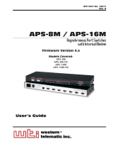
Figure 2.1: Instrument Front Panel (Model RSM-8 Shown)
2. Unit Description
2.1. Front Panel
CLEAR: Restarts the RSM without changing user-selected parameter settings.
Note: When Clear is pressed, all ports will be disconnected.
ON: Lights when AC Power is applied.
SET: Used to Initialize the RSM to default parameters. To initialize the RSM, press
and hold the SET button for approximately five seconds.
Notes:
• During initialization, all port LEDs will flash ON three times.
• After initialization, all command-selected parameters will be cleared, and the
RSM will revert to the default parameters. The default "super" user account
will also be restored.
RDY: (Ready) Flashes to indicate unit is operational.
ACTIVITY LEDs: A series of LEDs, which light to indicate data activity at the
corresponding port.
• RSM-8 units include 8 Activity LEDs
• RSM-16 and RSM-16DC units include 16 Activity LEDs
• RSM-32 and RSM-32DC units include 32 Activity LEDs.

2-2
Unit Description
O
I
PHONE
LINE
10/100BaseT
LINK
ACTIVITY
SYSTEM SETUP PORTS
(DTE)
1 2 3 4 5 6 7 8
1
2
3
4
5
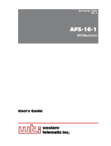
Figure 2.2: Instrument Back Panel (Model RSM-8)
O
I
PHONE
LINE
10/100BaseT
LINK
ACTIVITY
2
1
3
4
5
6
7
8
9
10
11
12
13
14
15
16
SYSTEM
SETUP
PORTS
(DTE)
1
2
3
3
4
5
Figure 2.3: Instrument Back Panel (Model RSM-16)
PHONE
LINE
10/100BaseT
LINK
ACTIVITY
2
1
3
4
5
6
7
8
9
10
11
12
13
14
15
16
18
17
19
20
21
22
23
24
25
26
27
28
29
30
31
32
SYSTEM
SETUP
PORTS
(DTE)
1
2
3
3
4
5
Figure 2.4: Instrument Back Panel (Model RSM-32)
2.2. Back Panel
As shown in Figures 2.2, 2.3 and 2.4, the RSM Back Panel includes the following
components:
Phone Line Port: For connection to your external phone line.
Network Port: An RJ45 Ethernet port for connection to your 10/100Base-T, TCP/IP
network. Note that the RSM features a default IP address (192.168.168.168). This
allows you to connect to the unit without first assigning an IP address. Note that the
Network Port also includes two, small LED indicators for Link and Data Activity. For
more information on Network Port configuration, please refer to Section 5.8.

2-3
Unit Description
RS232 Serial Ports: For connection to console ports on target devices. Standard
DB9 connectors configured as DTE ports. The RS232 ports are similar to a serial
port on a PC. When connecting a modem, use a standard serial cable. When
connecting a PC or other DTE device use a null modem cable.
• RSM-8 units include 8 Serial Ports.
• RSM-16 and RSM-16DC units include 16 Serial Ports.
• RSM-32 and RSM-32DC units include 32 Serial Ports.
Power Inlet: An IEC-320-C14 inlet, for connection to your 100 to 240 VAC power
supply. Note that RSM-16DC and RSM-32DC units (-48 VDC powered models)
include a terminal block assembly (see Figure 4.1) in place of the power inlet. For
more information, please refer to Section 4.1.
Power On/Off Switch

3-1
3. Getting Started
This section describes a simplified installation procedure for our RSM-8, RSM-16,
RSM-16DC, RSM-32 and RSM-32DC models, which will allow you to communicate with
the unit in order to demonstrate basic features and check for proper operation.
Note that this Quick Start Guide does not provide a detailed description of unit
configuration, or discuss advanced operating features in detail. In order to take full
advantage of the features provided by this unit, it is recommended that you should
complete the entire Installation and Configuration sections after performing this Quick
Start procedure.
3.1. Quick Hardware Installation
3.1.1. Apply Power to the RSM
Refer to the safety precautions listed at the beginning of this User’s Guide and in
Section 4, and then connect the unit to an appropriate power source. Note that RSM-8,
RSM-16 and RSM-32 units are designed for 100 to 240 VAC, 50/60 Hz operation and
feature an auto sensing power supply; while RSM-16DC and RSM-32DC models are
designed for -48 VDC operation.
When power is applied to the RSM, the ON LED should light, and the RDY LED should
begin to flash. Note however, that the boot up procedure may take up to two minutes;
this delay is due to the time required to generate SSH keys.
3.1.2. Connect your Control Device to the RSM
The RSM can either be controlled via local PC Serial Port, modem, or TCP/IP network.
In order to connect ports or select parameters, commands are issued to the RSM via
either the Network Port, Modem or RS232 Setup Port. Note that it is not necessary to
connect to both the Network and Setup Ports, and that the Setup Port can be connected
to either a local PC or an external modem.
• Network Port: Connect your 10Base-T or 100Base-T network interface to the RSM
10/100Base-T Network port.
• Console Port: Use the supplied null modem cable to connect your PC COM port
to the RSM Set-Up Port (RS232).
• Modem: Connect your phone line to the RSM’s Phone Line (Modem) port.

3-2
Getting Started
3.2. Communicating with the RSM
When properly installed and configured, the RSM will allow command mode access
via Telnet, Web Browser, SSH client, modem, or local PC. However, in order to ensure
security, both Telnet and Web Browser access are disabled in the default state. To
enable Telnet and/or Web Browser access, please refer to Section 5.8.
Notes:
• Default RSM serial port parameters are set as follows: 9600 bps, RTS/
CTS Handshaking, 8 Data Bits, One Stop Bit, No Parity. Although these
parameters can be easily redefined, for this Quick Start procedure, it is
recommended to configure your communications program to accept the
default parameters.
• The RSM features a default IP Address (192.168.168.168) and a default
Subnet Mask (255.255.255.0.) This allows network access to command
mode, providing that you are contacting the RSM from a node on the same
subnet. When attempting to access the RSM from a node that is not on the
same subnet, please refer to Section 5.8 for further configuration instructions.
1. Access Command Mode: The RSM includes two separate user interfaces; the Text
Interface and the Web Browser Interface. The Text Interface is available via Local
PC, SSH Client, Telnet, or Modem and can be used to both configure the RSM and
create connections between ports. The Web Browser interface is only available
via TCP/IP network, and can be used to configure the unit, but cannot create port
connections.
a) Via Local PC: Start your communications program and then press [Enter].
b) Via SSH Client: Start your SSH client, enter the default IP address
(192.168.168.168) for the RSM and invoke the connect command.
c) Via Web Browser: Make certain that Web Browser access is enabled as
described in Section 5.8. Start your JavaScript enabled Web Browser, enter
the default RSM IP address (192.169.168.168) in the Web Browser address bar,
and then press [Enter].
d) Via Telnet: Make certain that Telnet access is enabled as described in
Section 5.8.1. Start your Telnet client, and enter the RSM's default IP address
(192.168.168.168).
e) Via Modem: Use your communications program to dial the number for the line
connected to the RSM’s Phone Line port.
2. Username / Password Prompt: A message will be displayed, which prompts you
to enter your username (Login) and password.. The default username is "super"
(all lower case, no quotes), and the default password is also "super". If a valid
username and password are entered, the RSM will display either the Home Screen
(Web Browser Interface) or the Port Status Screen (SSH, Telnet, or Modem) as
shown in Figure 3.1 and Figure 3.2.

3-3
Getting Started
3. Review Help Menu: If you are communicating with the RSM via the text interface
(SSH, Telnet or Modem), type /H and press [Enter] to display the Help Menu,
which lists all available RSM commands. Note that the Help Menu is not available
via the Web Browser Interface.
4. Creating Connections Between Ports: The RSM can perform two types of
connections; Resident Connections and Third Party Connections. Note that Port
Connection commands are only available via the Text Interface, and cannot be
invoked via the Web Browser Interface.
a) Resident Connection: Your resident port (e.g. Port 1) issues a /C command to
connect to a second port.
i. To connect Port 1 to Port 2, type /C 2 [Enter]. While Port 1 is connected,
the RSM will not recognize commands issued at Port 1. However, the unit
will recognize a Resident Disconnect Sequence issued at Port 1 or Port 2.
ii. Issue the Resident Disconnect Sequence (Logoff Sequence); type ^X
(press [Ctrl] and [X] at the same time).
PORT STATUS:
Site ID: (undefined) 02/07/2007 00:23:39 GMT (GMT+0000)
PORT | NAME | USERNAME | STATUS | MODE | BUFFER COUNT
-----+------------------+------------------+--------+--------+--------------
01 | (undefined) | | Free | Any | 0
02 | (undefined) | | Free | Any | 0
03 | (undefined) | | Free | Pass | 0
04 | (undefined) | | Free | Pass | 0
05 | (undefined) | | Free | Pass | 0
06 | (undefined) | | Free | Pass | 0
07 | (undefined) | | Free | Pass | 0
08 | (undefined) | | Free | Pass | 0
09 | MODEM | | Free | Modem | 0
Enter /H for command menu.
RSM>
Figure 3.1: The Port Status Screen - Text Interface (RSM-8 Shown)
Figure 3.2: The Home Screen - Web Interface

3-4
Getting Started
b) Third Party Connection: Your resident port (e.g. Port 1) issues a /C command
to create a connection between two other ports.
i. To connect Port 2 to Port 3, type /C 2 3 [Enter].
ii. While Ports 2 and 3 are connected, Port 1 will still recognize RSM
commands. Type /S [Enter] to display the Port Status Screen. The
"STATUS" column should now list Ports 2 and 3 as connected, and Port 1
as "Free".
iii. Issue a Third Party Disconnect command to disconnect Ports 2 and 3; type
/D 2 [Enter]. The unit will display the "Are you Sure (y/n)?" prompt. Type
y and press [Enter] to disconnect.
iv. Type /S [Enter] to display the Port Status Screen. The Status screen
should now list Ports 2 and 3 as "Free".
5. Exit Command Mode: When you finish communicating with the unit via the text
interface, it is important to always log off using the appropriate RSM command,
rather than by simply closing your Telnet program. When you log off using the
proper command, this ensures that the unit has completely exited from command
mode, and is not waiting for the inactivity timeout to elapse before allowing
additional connections. To exit command mode, type /X and press [Enter].
This completes the RSM Quick Start procedure. Prior to placing the unit into operation,
it is recommended to refer to the remainder of this User’s Guide for important
information regarding advanced configuration capabilities and more detailed operation
instructions. If you have further questions regarding the RSM unit, please contact WTI
Customer Support as described in Appendix C.

4-1
-48V 0.1A
0
-48V
A
-48V
B
GROUND
SCREW
Figure 4.1: Terminal Block Assembly (DC Units Only)
4. Hardware Installation
4.1. Connecting Power to the RSM Unit
The RSM is available in both AC and DC powered versions. When connecting AC or DC
power to the RSM, proceed as follows:
CAUTIONS:
• Before attempting to install this unit, please review the warnings and
cautions listed at the front of the user's guide.
• This device should only be operated with the type of power source
indicated on the instrument nameplate. If you are not sure of the type
of power service available, please contact your local power company.
• Reliable earthing (grounding) of this unit must be maintained.
Particular attention should be given to supply connections when
connecting to power strips, rather than directly to the branch circuit.
4.1.1. AC Powered Units
Plug the power cable (supplied with the unit) into the receptacle on the RSM back panel.
Then, connect the power cable to an appropriate, grounded outlet. The RSM features
a self adjusting power supply that automatically adapts to power supplies between 90
and 250 VAC. Press the Power Switch ON. The ON LED should light and the RDY LED
should begin to flash.
4.1.2. DC Powered Units
When connecting the RSM to your DC Power source, first remove the protective cover
from the terminal block, attach the wires from the -48 VDC power source to the screw
terminals, connect the ground line to the labeled ground screw, and then replace the
protective cover.

4-2
Hardware Installation
4.2. Connecting the Network Cable
The Network Port is an RJ45, 10/100BaseT Ethernet Jack, for connection to a TCP/IP
network. Note that the RSM features a default IP Address (192.168.168.168.) Providing
that you are communicating with the unit from a node on the same subnet, this allows
you to contact the RSM without first accessing command mode to assign an IP address.
When installing the RSM in a working network environment, it is recommended to
assign the IP Address, Gateway Address, and Subnet Mask as described in Section 5.8.
4.3. Connecting Devices to the RSM
1. Determine which RSM port will be used for connection to the new device
(e.g. Port 3).
2. Use an appropriate DB9 cable to connect the RS232 serial port on the device to a
DB9 port on the RSM.
a) External Modems and other DCE Devices: Use a standard serial
modem cable.
b) PCs and other DTE Devices: Use a null modem cable.
3. Access the RSM command mode and select communication parameters for each
RSM port as described in Section 5.7.

5-1
5. Configuration
5.1. Communicating with the RSM Unit
In order to configure the RSM, you must first connect to the unit, and access command
mode. Note that, the RSM offers two separate configuration interfaces; the Web
Browser Interface and the Text Interface.
In addition, the RSM also offers three different methods for accessing command mode;
via network, via modem, or via local console. The Web Browser interface is only
available via network, and the Text Interface is available via network (SSH or Telnet),
modem or local PC.
5.1.1. The Text Interface
The Text Interface consists of a series of simple ASCII text menus, which allow you to set
options and define parameters by entering the number for the desired option using your
keyboard, and then typing in the value for that option.
Since the Web Browser Interface and Telnet accessibility are both disabled in the
default state, you will need to use the Text Interface to contact the unit via Local PC or
SSH connection when setting up the unit for the first time. After you have accessed
command mode using the Text Interface, you can then enable Web Access and
Telnet Access in order to allow future communication with the unit via Web Browser or
Telnet. You will not be able to contact the unit via Web Browser or Telnet until you have
specifically enabled those options.
Once Telnet Access is enabled, you will then be able to use the Text Interface to
communicate with the RSM via local PC, Telnet or SSH connection. You can also use
the text interface to access command mode via the RSM's internal modem, or via an
external modem installed at one of the RSM's RS232 serial ports.
In order to use the Text Interface, your installation must include:
• Access via Network: The RSM must be connected to your TCP/IP Network, and
your PC must include a communications program (such as HyperTerminal.)
• Access via Modem: A phone line must be connected to the RSM's Phone Line
port, and your PC must include a communications program.
• Access via Local PC: Your PC must be physically connected to one of the
RSM’s RS232 ports as described in Section 4.3, and your PC must include a
communications program.
/