
APS Series
Asynchronous Port Switches
Firmware Version 2.05 and Higher
Models APS-16, APS-8 and APS-4
User's Guide
5 Sterling Irvine California 92618
(949) 586-9950
Toll Free: 1-800-854-7226
Fax: (949) 583-9514
http://www.wti.com

Warnings and Cautions:
No Serviceable Parts Inside;
Authorized Service Personnel Only
Do not attempt to repair or service this device yourself. Internal components must be serviced
by authorized personnel only.
Shock Hazard - Do Not Enter
Choc Hasard - N'entrent
Schocke Hazard - Test Nicht Betrete
Otro Hazard - Do Non Entrano
Nameplate Power Warning
This device should only be operated with the type of power source indicated on the instrument
nameplate. If you are not sure of the type of power service available, consult your local power
company.
Connect unit only to a properly measured supply. Use only three wire cord which is
provided with the unit.
Abouchent unité qu'aux convenable mesura approvisionnement. Usage qu'à trois fil
corde laquel est approvisionna avec la unité.
Anschliesse einheit nur bis ein angebracht gemessen nachschub. Gebrauch nur drei
draht schnur welche ist verschaffen mit das einheit.
Connect unità solo a un proper misurata fornirle. Adoperano solo tre wire spago quale
è fornii con gli unità.
Battery Replacement
This device may include a lithium battery powered circuit. If the battery is incorrectly
replaced or mistreated, there is a danger of explosion and a risk of personal injury. Do not
attempt to recharge the battery, disassemble it, immerse it in water, or dispose of it in a fire.
Battery replacement may only be performed by authorized service personnel.
i

Rack Mount Installation
When installing this device in an instrument rack, the following factors must be accounted for:
1. Enclosed Racks: Enclosed racks must provide adequate ventilation. Make certain that
the rack is not overly crowded and note that each unit in the rack generates its own heat.
An enclosed rack should have louvered sides and a fan to circulate cooling air. The
maximum temperature for the equipment in this environment is 45° C.
When mounting the unit in an enclosed rack with a ventilation fan at the top of the rack,
note that excessive heat generated by devices at the bottom of the rack can be drawn
upward and into the ventilation slots of units located at the top. Make certain to provide
adequate ventilation for equipment installed at the bottom of the rack.
2. Open Racks: Make certain that the rack frame does not block the ventilation slots on the
instrument cover. If the device is installed on sliders, check the unit when seated all the
way into the rack to make certain that ventilation slots are not blocked.
Ventilation
Slots in the instrument cover are provided to allow ventilation for heat dissipation. To ensure
safe, reliable operation, these openings must not be covered or blocked.
Disconnect Power
If any of the following events are noted, immediately disconnect the unit from the outlet and
contact qualified service personnel:
1. If the power cord becomes frayed or damaged.
2. If liquid has been spilled into the device or if the device has been exposed to rain or
water.
ii

Table of Contents
1. Introduction
.............................................
1-1
2. Unit Description
..........................................
2-1
2.1. Front Panel
..........................................
2-1
2.2. Back Panel
..........................................
2-2
3. Getting Started
...........................................
3-1
3.1. Communication Parameters
.................................
3-1
3.2. Apply Power to the APS
...................................
3-1
3.3. System SetUp Ports
.....................................
3-2
3.4. Connecting your PC to the APS
..............................
3-2
3.5. Communicating with the APS Unit
............................
3-2
4. Hardware Installation
.......................................
4-1
4.1. Connecting Power to the APS Unit
............................
4-1
4.1.1. AC Powered Units
.................................
4-1
4.1.2. DC Powered Units
.................................
4-1
4.2. Configure SetUp Switches .................................4-2
4.2.1. Default Baud Rate (Sw1, Sw2, Sw3) .......................4-2
4.2.2. Default Handshake (Sw4, Sw5) ..........................4-3
4.2.3. Default Response Message Format (Sw6) ....................4-3
4.2.4. Default Command Echo (Sw7) ..........................4-3
4.3. Initialize Unit to Default Settings .............................4-4
4.4. Connecting Devices to the APS ..............................4-4
4.5. Application Example.....................................4-5
5. Configuration ............................................5-1
5.1. Access to the APS Command Mode ............................5-1
5.2. System SetUp Ports .....................................5-1
5.3. Password Functions
.....................................
5-1
5.3.1. The Supervisor Password
.............................
5-2
5.3.2. The Port Passwords
.................................
5-2
5.4. Defining the Site ID and Supervisor Password
......................
5-3
5.5. Port Configuration
......................................
5-4
5.5.1. Configuration Conventions
............................
5-4
5.5.2. Port Modes
......................................
5-4
5.5.3. RS232 Port Configuration Menus
.........................
5-5
5.6. Copying Parameters to All Ports
..............................
5-9
5.7. Save User Selected Parameters
..............................
5-10
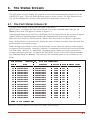
6. The Status Screens
.........................................
6-1
6.1. The Port Status Screen (/S)
.................................
6-1
6.2. The Port Diagnostics Screen (/SD)
.............................
6-2
6.3. The Port Parameters Screens (/W)
.............................
6-4
iii

7. Operation
..............................................
7-1
7.1. Any-to-Any Mode
......................................
7-1
7.1.1. Port Connection and Disconnection
.......................
7-1
7.1.1.1. Connecting Ports
.............................
7-1
7.1.1.2. Disconnecting Ports
...........................
7-2
7.1.2. Defining Hunt Groups
...............................
7-3
7.2. Passive Mode
.........................................
7-4
7.3. Buffer Mode
..........................................
7-4
7.3.1. Reading Data from Buffer Mode Ports
......................
7-5
7.3.2. Port Buffers
.....................................
7-5
7.4. Modem Mode
.........................................
7-6
8. Saving and Restoring Configuration Parameters
......................
8-1
8.1. Sending Parameters to a File
................................
8-1
8.2. Restoring Saved Parameters
.................................
8-2
9. Command Reference Guide
...................................
9-1
9.1. Command Conventions
...................................
9-1
9.2. Command Response
.....................................
9-2
9.3. Command Summary
.....................................
9-3
9.4. Command Set
.........................................
9-4
Appendices:
A. RS232 Port Interface......................................Apx-1
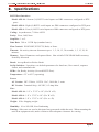
B. Specifications ..........................................Apx-2
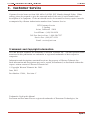
C. Customer Service ........................................Apx-3
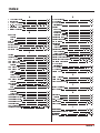
Index .................................................Index-1
List of Figures
2.1. Instrument Front Panel (Model APS-16 Shown)
.......................
2-1
2.2. Instrument Back Panel (Model APS-16)
............................
2-2
2.3. Instrument Back Panel (Model APS-8)
.............................
2-2
2.4. Instrument Back Panel (Model APS-4)
.............................
2-2
3.1. The Supervisor Level Help Screen
...............................
3-3
3.2. The Port Status Screen (Model APS-16; Defaults Shown)
..................
3-4
4.1. Terminal Block Assembly (DC Units Only)
..........................
4-1
4.2. APS Application Example (Model APS-16 Shown)
.....................
4-5
5.1. Port Configuration Menu (Port 2 Shown)
...........................
5-5
5.2. Port Parameters Menu (Modem Mode)
.............................
5-7
5.3. The Copy Port Parameters Menu
................................
5-9
6.1. The Port Status Screen (Supervisor Mode, APS-16 Shown)
.................
6-1
6.2. The Port Diagnostics Screen (APS-16 Shown)
........................
6-2
6.3. The Port Parameters Screen
...................................
6-4
A.1. RS232 Port Interface
.....................................
Apx-1
iv

1. Introduction
WTI’s APS-16, APS-8, and APS-4 Asynchronous Port Switches allow reliable, high-speed
connections between PCs, modems, and other devices using dissimilar baud rates, parity, and
flow control. The APS supports communication at speeds up to 115.2 Kbps, and features full
RTS/CTS hardware handshaking. Lightening-swift data throughput and full flow control make
the APS the perfect data switch for today’s high speed communications applications.
Versatile Connectivity
Up to 16 different devices can be connected to the APS without the need to select a common
baud rate or parity. Each port can be individually configured for specific baud rates, parity,
handshaking, and various other parameters and options.
Easy Set-Up and Operation
Configuration of the APS is simple. A menuing system is used to select communications
parameters, and enable or disable options. The APS can easily adapt to the requirements of
almost any data communications application.
Limited Command Access
The APS is ideal for situations that require limited access to important commands. Two
security levels allow each port to function as a Supervisor Port or User Port, depending on the
password entered at login. Supervisor Ports are allowed to change configuration, display
status, and connect to any other port; User Ports are only allowed to connect to the ports
provided by their password. Each individual port can be assigned its own unique, user-defined
password, up to sixteen characters long.
Password Protected Connection and Command Access
The convenient password feature provides restricted access to command functions, and also
restricts unauthorized connection to specific ports. Each individual port can be assigned its
own unique, user-defined password, up to sixteen characters long.
Non-Volatile Memory
If power to the unit is lost or interrupted, the APS’s non-volatile memory will retain user-
defined parameters and port connections.
Modem Communication
The APS can be controlled by a local PC that communicates with the unit via cable, or
controlled remotely via external modem. ProComm
(or another communications program) is
used to send commands to connect ports or display status.
Configuration Backup
Once you have configured the APS to fit your application, parameters and options can be saved
to an ASCII text file on your PC. This allows you to quickly restore user-selected parameters
if the unit configuration is accidentally altered or deleted. Saved parameters can also be
uploaded to other APS units. This allows rapid set-up when several units will be configured
with identical or similar parameters.
1-1

APS-16, APS-8, and APS-4 Units
This User’s Guide discusses the APS-16, APS-8 and APS-4 Asynchronous Port Switches.
Throughout this User’s Guide, all three units are referred to as "the APS". The APS-16
includes sixteen RS232 ports, the APS-8 includes eight RS232 ports, and the APS-4 includes
four RS232 ports. All other features function identically.
Typographic Conventions
^ (e.g. ^X) Indicates a control character. For example, the text "^X" (Control X)
indicates the [Ctrl] key and the [X] key must be pressed simultaneously.
COURIER FONT Indicates characters typed on the keyboard. For example, /E or /P 02.
[Bold Font] Text set in bold face and enclosed in square brackets, indicates a specific
key. For example, [Enter] or [Esc].
<> Indicates required keyboard entries. For Example: /P <n>.
[] Indicates optional keyboard entries. For Example: /W [n].
1-2

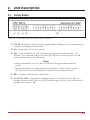
2. Unit Description
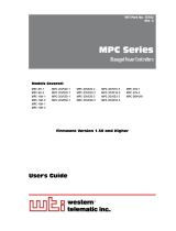
2.1. Front Panel
¬
CLEAR: Restarts the APS operating program without changing user-selected parameter
settings or breaking port connections.
ON: Lights when AC Power is applied.
® SET: Used to Initialize the APS to defaults specified by the SetUp Switches. To
initialize, press and hold both the SET and CLEAR buttons, release only the CLEAR
button, and then release the SET button.
Notes:
• During initialization, all port LEDs will flash ON for approximately one half
second.
• During initialization, all command-selected parameters will be cleared, and the
APS will revert to the default parameters specified by the SetUp Switches.
¯ RDY: Flashes to indicate unit is operational.
° ACTIVITY LEDs: Light when corresponding port is receiving data. The APS-16
includes sixteen Activity LEDs, the APS-8 includes eight Activity LEDs, and the APS-4
includes four Activity LEDs.
2-1
Figure 2.1: Instrument Front Panel (Model APS-16 Shown)

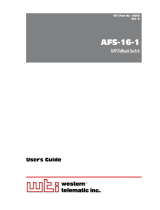
2.2. Back Panel
¬
RS232 PORTS: For connection to RS232 console ports on user devices. For more
information, please refer to Section 4.4 (connection instructions), Appendix A (interface
description), and Section 5.2 (Setup Ports).
SetUp Switches: A bank of eight DIP switches, which set default communication
parameters and other features. Note that on APS-16 units, SetUp Switches are located on
the underside of the unit; on APS-8 and APS-4 units, the SetUp Switches are located on
the instrument back panel.
® 115/230 Voltage Selector: AC powered units only.
¯ Power Switch
° Power Cable Receptacle AC powered units only. DC units include a terminal block
assembly as described in Section 4.1.
2-2
Figure 2.2: Instrument Back Panel (Model APS-16)
Figure 2.3: Instrument Back Panel (Model APS-8)
Figure 2.4: Instrument Back Panel (Model APS-4)

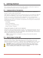
3. Getting Started
This section provides a brief overview of basic APS capabilities, and describes simple tests
that can be used to determine if the unit is operating properly.
3.1. Communication Parameters
The SetUp Switches select default operating settings. Switch functions are summarized in
Section 4.2, and on a label on the APS unit.
When the unit is shipped from the factory, the SetUp Switches are set for 9600 baud, 8 Bits-No
Parity, RTS/CTS handshaking, verbose response, and command echo On (all switches ON).
For this overview only, use the default switch configuration. Set your communications
program (e.g. ProComm
) to the parameters listed below. After completing this overview and
installing the unit, please refer to Section 5 for instructions on selecting faster communication
speeds and other parameters.
·
9600 Baud
·
RTS/CTS Handshaking
·
Full Duplex (Command Echo ON)
·
8 Bits, No Parity, 1 Stop Bit
Using Other Parameters for this Overview (Optional):
If desired, the APS can match the parameters used by your communications program. Refer to
Section 4.2 and configure SetUp Switches accordingly. After changing the switches, reset the
APS: press and hold both the SET and CLEAR buttons, release only CLEAR, wait for the Port
LEDs to flash, and then release the SET button.
Note: If SetUp Switches are changed, new settings will not take effect until the
unit is initialized.
3.2. Apply Power to the APS
For AC units, the Voltage Selector Switch on the instrument back panel is used to set the unit
for 115V or 230V AC power. When connecting power to a DC unit, please refer to the
additional instructions in Section 4.1. Connect the APS to an appropriate power source. Press
the Power Switch ON. The ON LED should light, and the RDY LED should begin to flash.
CAUTION: This device should only be operated with the type of power source
indicated on the instrument nameplate. If you are not sure of the type of power
service available, please consult your local power company.
3-1

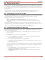
3.3. System SetUp Ports
In order to ensure access to command functions, Ports 1 and 2 are designated as System SetUp
Ports; the Supervisor Mode cannot be disabled at these ports. Ports 1 and 2 will always allow
password protected access to all APS command functions, even when the unit has been reset to
the default state.
Therefore, Ports 1 and 2 are generally used for communication during initial set-up and
configuration, or after the unit has been reinitialized (reset) to default parameters.
3.4. Connecting your PC to the APS
The APS can be controlled by a local PC directly connected to the APS, or controlled remotely
via external modem. For this overview, a local PC running ProComm (or a similar
communications program), will be cabled to Port 1.
Note: Communication via Modem (Optional): This overview can also be
performed via modem. Section 4.4 describes the procedure for connecting a modem
to the APS.
Attach a standard null modem cable to your PC COM port. Make certain to connect to the
COM port used by your communications program. Connect the other end of the cable to APS
Port 1. For a description of the port interface, please refer to Appendix A.
3.5. Communicating with the APS Unit
Perform the following procedure to access the APS Command Mode, explore basic features,
and check for proper operation.
1. Start your communications program (e.g. ProComm) and set it to 9600 bps, 8 bits, no
parity, 1 stop bit.
2. Press [Enter] to access the APS Command Mode.
a) In order for [Enter] to be recognized as a wake-up command, it must be pressed
without any characters preceding it.
b) If you have already hit other keys, press [Enter] twice.
c) (Optional) If you are performing this overview via modem, refer to Section 5.1 for
additional instructions.
3. The Port Status Screen will be displayed, followed by the "APS>" prompt, indicating that
you have successfully accessed Command Mode. If the prompt is not displayed, check
the following:
a) Cable Connection: Check the connection between the APS and the PC. Make
certain the cable connectors are firmly seated.
b) Communication Parameters: Make certain the APS and ProComm are using the
same baud rate.
3-2

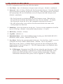
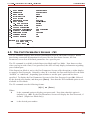
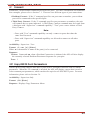
4. Help Screen: Type /H [Enter] to display the Supervisor Level Help Screen (Figure 3.1).
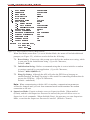
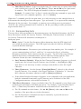
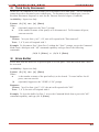
5. Port Status Screen: Type /S [Enter] to display the Port Status Screen (Figure 3.2),
which summarizes conditions at all Ports. Note that the APS-8 Port Status Screen will
list only eight ports, and the APS-4 Port Status Screen will list only four ports. The
various fields of the Port Status Screen are further explained in Section 6.1.
6. Port Connection: The APS can perform two different types of port connections;
Resident Connections and Third Party Connections.
a) Resident Connection: Your resident port (e.g. Port 1) issues a /C command to
connect to a second port.
i. To connect Port 1 to Port 2, type /C 2 [Enter]. While Port 1 is connected, the
APS will not recognize commands issued at Port 1. However, the unit will
recognize a Resident Disconnect Sequence issued at Port 1 or Port 2.
ii. Issue the Resident Disconnect Sequence (Logoff Sequence); type ^X (press
[Ctrl] and [X] at the same time).
3-3
Figure 3.1: The Supervisor Level Help Screen

b) Third Party Connection: Your resident port (e.g. Port 1) issues a /C command to
create a connection between two other ports.
i. To connect Port 2 to Port 3, type /C23[Enter].
ii. While Ports 2 and 3 are connected, Port 1 will still recognize APS commands.
Type /S [Enter] to display the Port Status Screen. The "STATUS" column
should now list Ports 2 and 3 as connected, and Port 1 as "Free".
iii. Issue a Third Party Disconnect command to disconnect Ports 2 and 3; type /D 2
[Enter]. The unit will display the "Are you Sure (y/n)?" prompt. Type y and
press [Enter] to disconnect.
iv. Type /S [Enter] to display the Port Status Screen. The "STATUS" column
should now list Ports 2 and 3 as "Free".
7. Site I.D. Message: If desired, the Site I.D. Message can be used to indicate the name or
location of the unit. Note that the Site I.D. cannot include double quotes (”).
a) Type /F and press [Enter]. When the System Parameters menu appears, type 1 and
press [Enter]. A prompt will appear. Key in the desired text (up to 32 characters)
and press [Enter].
b) To display the Site I.D., type /J [Enter].
c) Note that the Site I.D. will be cleared when the
unit is initialized.
This completes the introductory overview of the APS. Please proceed to Sections 4 and 5 for
complete installation and configuration procedures.
3-4
Figure 3.2: The Port Status Screen (Model APS-16; Defaults Shown)

4. Hardware Installation
4.1. Connecting Power to the APS Unit
The APS is available in both AC and DC powered versions. When connecting AC or DC power
to the APS, proceed as follows:
CAUTION: This device should only be operated with the type of power source
indicated on the instrument nameplate. If you are not sure of the type of power
service available, please contact your local power company.
4.1.1. AC Powered Units
The Voltage Selector Switch on the instrument back panel is used to set the unit for 115V or
230V AC power. Plug the supplied power cable into the receptacle on the APS back panel and
then connect the power cable to a grounded AC outlet.
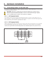
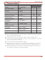
4.1.2. DC Powered Units
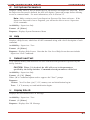
When connecting the APS to your DC power source, first remove the protective cover from the
DC terminal block, attach the wires from the -48 VDC power source to the screw terminals,
connect your ground line to the labeled ground screw, and then replace the protective cover.
4-1
Figure 4.1: Terminal Block Assembly (DC Units Only)

4.2. Configure SetUp Switches
The SetUp Switches are used to select default settings for the APS RS232 ports. On model
APS-16 , the SetUp Switches are located on the underside of the unit. On APS-8 and APS-4
models, the SetUp Switches are located on the instrument
back panel.
When the APS is shipped from the factory, the SetUp Switches are configured for 9600 baud, 8
Bits-No Parity, RTS/CTS handshaking, verbose command response, and command echo on (all
switches ON). These settings are compatible with most applications. If the default settings are
not compatible with your application, change the switch settings as follows.
Notes:
•
The SetUp Switches should be configured to match the parameters your control
device will use when communicating with the APS. This will ensure access to
command functions, even if the unit is initialized to default parameters.
•
If the SetUp Switch configuration is changed, new parameters will not take effect
until the unit is initialized as described in Section 4.3.
•
Operating parameters (baud rate, parity, etc.) can be selected for each port using
the /P command as described in Section 5.5. The /P command can select different
parameters for each APS port.
• When the APS is initialized, parameters will return to settings specified by the
SetUp Switches.
On/Off Positions: On the APS-8 and the APS-4 (Switches on Back Panel), the switches are
ON when placed in the DOWN position. On the APS-16 (Switches on underside of unit)
On/Off positions are indicated on a label adjacent to the SetUp Switches.
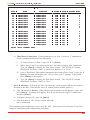
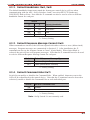
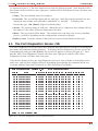
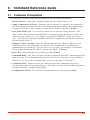
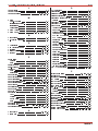
4.2.1. Default Baud Rate (Sw1, Sw2, Sw3)
SetUp Switches one through three select the default baud rate for all APS RS232 Ports. The
default baud rate must match the rate your control device will use when communicating with
the APS. If the control device will communicate via modem, select a default baud rate that is
compatible with the modem. Note that the /P command can also be used to select a different
operating baud rate for each port.
SW
Default Baud Rate
123
ON ON ON 9600*
OFF ON ON 300
ON OFF ON 1200
OFF OFF ON 2400
ON ON OFF 19.2K
OFF ON OFF 38.4K
ON OFF OFF 57.6K
OFF OFF OFF 115.2K
* = Factory Setting
4-2

4.2.2. Default Handshake (Sw4, Sw5)
The default handshake format must match the format your control device will use when
communicating with the APS. SetUp Switches 4 and 5 can select RTS/CTS (hardware),
XON/XOFF, Both or None. Note that the /P command can also be used to select a different
handshake format for each port.
Switch
Default Handshake
45
ON ON RTS/CTS *
OFF ON XON/XOFF
ON OFF Both
OFF OFF None
* = Factory Setting
4.2.3. Default Response Message Format (Sw6)
When commands are invoked, the APS can respond with either verbose or terse (abbreviated)
messages. Response messages are summarized in Section 9.2. After installation, the /P
command can also set the response format to "none" (Quiet Mode). When Quiet Mode is
selected, the unit will not send response messages. Note that the /P command can also be used
to select a different Response Message format for each port.
Switch 6 Default Response Message Type
ON Verbose (English Text) *
OFF Terse (abbreviated / numeric)
* = Factory Setting
4.2.4. Default Command Echo (Sw7)
Switch Seven enables or disables the Command Echo. When enabled, characters sent to the
APS will be echoed back to the control device. Note that the /P command can also be used to
selectively enable or disable the Command Echo at each individual port.
Switch 7 Default Command Echo
ON Enable*
OFF Disable
* = Factory Setting
Note: SetUp Switch 8 is not currently used.
4-3

4.3. Initialize Unit to Default Settings
If SetUp Switch settings are changed, new parameters will not take effect until the APS is
initialized.
CAUTION: After initialization, the APS will revert to the parameters specified
by the SetUp Switches. Any command-selected parameters will be lost.
1. Simultaneously press the SET and CLEAR buttons, located on the face of the APS.
2. Release the CLEAR button, wait for the Port LEDs to flash, and then release the SET
button.
4.4. Connecting Devices to the APS
The APS RS232 Ports are standard DB9 connectors, configured as DTE Ports, and are similar
to a standard serial port on a PC.
1. Access the APS Command Mode.
2. Determine which APS port will be used for connection to the new device (e.g. Port 3).
3. Check Buffer: Type /S [Enter] to display the Port Status Screen. Check the "Buffer
Count" column, which lists the amount of data stored in the buffer for each port.
a) If the Port Status Screen shows data stored in the buffer for the desired port, type /E
xx [Enter] to clear the buffer (where xx is the desired port number).
b) Note that cleared data cannot be recovered.
4. Use an appropriate DB9 cable to connect the RS232 serial port on the device to the
selected DB9 port on the APS.
a) External Modems and other DCE Devices: Use a standard serial modem cable.
b) PCs and other DTE Devices: Use a standard null modem cable.
5. Select communication parameters for the port as described in Section 5.
4-4

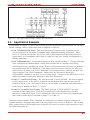
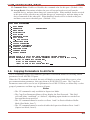
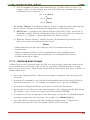
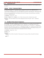
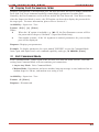
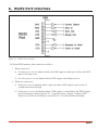
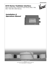
4.5. Application Example
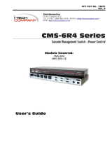
The example in Figure 4.2 shows one of many possible installation configurations for the APS.
In this example, APS-16 ports have been configured as follows:
·
Port 1 (System SetUp Port): This port has been left open in order to permit on-site
service personnel to access the Command Mode without disrupting other ports. Since
Port 1 is a System SetUp Port, the service tech is allowed password protected access to
Supervisor Level commands, and is able to connect to any port, change configuration, or
display unit status.
·
Port 2 (Modem Port): An external modem has been installed at Port 2. This port has also
been configured for Modem Mode, which allows definition of a modem reset string,
initialization string, and hang-up string. When a caller contacts the APS unit via modem, a
password prompt will be displayed. If the Supervisor Password is entered, the APS will
permit access to Supervisor Level Commands; if a Port password is entered, the APS will
only recognize User Level Commands. Supervisors are allowed to adjust port
configuration, connect to any port, or review unit status. Users are only allowed to review
status and connect to the ports allowed by their Port Password.
·
Ports 5, 7, and 9 (User Ports): The Port Password “COLOCATION1” has been assigned
to these three ports. If the APS is contacted via the Modem Port, and this password is
entered at log in, User’s will only be able to review status of permitted ports and connect
to the devices attached to Ports 5, 7, and 9.
·
Ports 12, 14, and 16 (User Ports): The Port Password “COLOCATION2” has been
assigned to these three ports. If the APS is contacted via the Modem Port, and this
password is entered at log in, User’s will only be able to review status of permitted ports
and connect to the devices attached to Ports 12, 14, and 16.
Note that in this example, Ports 3 through 16 could also be a mixture of ports connected to
external modems, and ports connected to devices such as file servers or archives. This would
allow remote users to dial in and access a specific file server or archive after entering a valid
Port Password at log in.
4-5
Figure 4.2: APS Application Example (Model APS-16 Shown)

5. Configuration
5.1. Access to the APS Command Mode
When the APS Command Mode is active, commands can be invoked to select parameters, and
connect or disconnect ports.
Note: Command Mode cannot be accessed from a Buffer Mode Port, Passive Mode
Port, or any port that is currently connected to another APS port.
1. Start your communications program (e.g. ProComm
). Make certain the APS and
ProComm are set for the same parameters (e.g. baud rate, parity, etc.).
2. Access the Command Mode.
a) Local Access: To access the command mode from a local PC that is connected to the
APS via cable, press [Enter].
i. There must be no other characters preceding [Enter]. If you have already hit
other keys, press [Enter] twice.
ii. If the Supervisor Password has been defined, the password prompt will be
displayed. Key in your Supervisor or Port password and press [Enter]. The
"APS>" prompt will appear.
b) Modem Access: To access the command mode via modem, proceed as follows:
i. Dial the number for the external modem connected to the APS.
ii. If you have defined the Supervisor Password, a prompt will be displayed. Key in
your Supervisor or Port password and press [Enter]. If the Supervisor Password
has not been defined, just press [Enter]. The "APS>" prompt will appear.
5.2. System SetUp Ports
As discussed previously in Section 3 of this User’s Guide, Ports 1 and 2 are designated as
System SetUp Ports. Ports 1 and 2 will always permit password protected access to Supervisor
Level command functions, even when the unit is initialized to default parameters.
In order to ensure that access to command functions is always available, Ports 1 and 2 cannot
be configured as Buffer Mode or Passive Mode Ports (Buffer and Passive Mode Ports are not
able to access the Command Mode.) In addition, Ports 1 and 2 always permit password
protected access to Supervisor Level commands; the Supervisor Mode cannot be disabled at
these two ports.
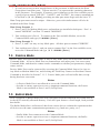
5.3. Password Functions
The APS features two different types of passwords; the Supervisor Password and the Port
(User) Passwords. The Supervisor Password allows system administrators to invoke unit
configuration commands, and the Port Passwords allow users to access specific ports in order
to create connections between permitted ports or view port configuration parameters.
5-1

5.3.1. The Supervisor Password
The Supervisor Password allows access to higher level APS configuration commands, which
administrators can employ to select communication parameters, assign port access rights, and
perform other system management tasks.
After the Supervisor Password has been defined (via the System Parameters menu), the APS
will display a password prompt whenever you attempt to access the command mode. If the
correct Supervisor Password is entered, the APS command mode then starts up in Supervisor
Mode. Supervisor Level commands are summarized in Section 9.3 of this User’s Guide.
Notes:
•
If the Supervisor Password is not defined, then Supervisor Level commands will
be available to all ports, and port access and configuration functions will not be
password protected.
•
If you wish to restrict user ports from changing APS configuration parameters or
connecting to restricted ports, the Supervisor Password must be defined.
•
When the Supervisor Password is defined, the APS will display a password
prompt when you attempt to access the command mode. Any RS232 port that has
not been assigned a Port Password, can then only be accessed using the Supervisor
Password.
• When defining a Supervisor Password, it is strongly recommended that you record
the password for future use. If you forget or lose your Supervisor Password, you
will not be able to access Supervisor Level Commands. In this case, the only way
to access the Supervisor Mode, is to reinitialize the APS to default values as
described in Section 4.2.
Normally, the Supervisor Password can be entered at any port in order to gain access to
Supervisor Level commands. Note that if you wish to completely deny a port’s access to
Supervisor Mode (even with the Supervisor Password), the Port Parameters menus (/P) can be
used to disable the Supervisor Mode at ports 3 through 16. The Supervisor Mode cannot be
disabled at System SetUp Ports 1 and 2.
Note that if the unit is reset to default parameters, all ports will revert to the default state,
where Supervisor Level commands are available to all ports, without password protection.
5.3.2. The Port Passwords
The Port Passwords (or User Passwords) allow system administrators to restrict access to a
specific group of ports. When the APS command mode is accessed with a Port Password, users
may only connect to the RS232 Ports to which they have been granted access, and review
configuration parameters for those ports. Port Passwords do not grant access to APS
configuration commands.
The configuration menus (/P) for each RS232 port allow a Port Password to be assigned to each
individual port. In order to allow a Port Password to grant access to a group of APS ports, the
same Port Password is assigned to each port in the group.
5-2
Page is loading ...
Page is loading ...
Page is loading ...
Page is loading ...
Page is loading ...
Page is loading ...
Page is loading ...
Page is loading ...
Page is loading ...
Page is loading ...
Page is loading ...
Page is loading ...
Page is loading ...
Page is loading ...
Page is loading ...
Page is loading ...
Page is loading ...
Page is loading ...
Page is loading ...
Page is loading ...
Page is loading ...
Page is loading ...
Page is loading ...
Page is loading ...
Page is loading ...
Page is loading ...
Page is loading ...
Page is loading ...
Page is loading ...
Page is loading ...
Page is loading ...
Page is loading ...
Page is loading ...
Page is loading ...
Page is loading ...
-
 1
1
-
 2
2
-
 3
3
-
 4
4
-
 5
5
-
 6
6
-
 7
7
-
 8
8
-
 9
9
-
 10
10
-
 11
11
-
 12
12
-
 13
13
-
 14
14
-
 15
15
-
 16
16
-
 17
17
-
 18
18
-
 19
19
-
 20
20
-
 21
21
-
 22
22
-
 23
23
-
 24
24
-
 25
25
-
 26
26
-
 27
27
-
 28
28
-
 29
29
-
 30
30
-
 31
31
-
 32
32
-
 33
33
-
 34
34
-
 35
35
-
 36
36
-
 37
37
-
 38
38
-
 39
39
-
 40
40
-
 41
41
-
 42
42
-
 43
43
-
 44
44
-
 45
45
-
 46
46
-
 47
47
-
 48
48
-
 49
49
-
 50
50
-
 51
51
-
 52
52
-
 53
53
-
 54
54
-
 55
55


Western Telematic APS-16 User manual
- Type
- User manual
- This manual is also suitable for
Ask a question and I''ll find the answer in the document
Finding information in a document is now easier with AI
Related papers
-
 Western Telematic RSM-32 User manual
-
 Western Telematic SRM-100 User manual
-
WTI PLS-345 User manual
-
-
 Western Telematic NPS-2HD User manual
-
 Western Telematic IPS-15 User manual
-
 Western Telematic MPC-20V-1 MPC-8H-2 User manual
-
Western Telematic M User manual
-
 Western Telematic AFS-16-1 User manual
-
Western Telematic Switch APS-8M User manual


Other documents
-
Black Box SWI082 User manual
-
 I-Tech Company Network Card CMS 6R4 Series User manual
-
Legrand Power Commander IQ - SPDU8-1U, SPDU16-2U, SPDU20-OU User guide
-
-
Patton electronic 2120 User manual
-
-
Allen-Bradley SLC 500 Series User manual
-
Xtreme SPD-0215 User manual
-
ADC MM701F User manual
-
 Varec TankGate Interface 8315 Series User manual

