Page is loading ...

MAN050 Rev 4/10/06
SM-nXm-C5AV-LCD
Audio/Video Matrix Switch via CAT5
Installation and Operation Manual
Used with NTI ST-C5VA-600 (XTENDEX
TM
) (NOT INCLUDED)
V
EEMUX
®
Series
NETWORK
TECHNOLOGIES
INCORPORATED
Tel:330-562-7070
Fax:330-562-1999
1275 Danner Dr
Aurora, OH 44202
www.networktechinc.com
NTI
R

i
MAN050 Rev 4/10/06
TRADEMARK
VEEMUX is a registered trademark of Network Technologies Inc in the U.S. and other countries
COPYRIGHT
Copyright © 2003-2006 by Network Technologies Inc. All rights reserved. No part of this publication may be reproduced, stored
in a retrieval system, or transmitted, in any form or by any means, electronic, mechanical, photocopying, recording, or otherwise,
without the prior written consent of Network Technologies Inc, 1275 Danner Drive, Aurora, Ohio 44202.
CHANGES
The material in this guide is for information only and is subject to change without notice. Network Technologies Inc reserves the
right to make changes in the product design without reservation and without notification to its users.
Note: Shielded CAT 5,5e, or 6 cable must be used to connect to LOCAL and REMOTE units in order to meet CE emission
requirements.

ii
MAN050 Rev 4/10/06
TABLE OF CONTENTS
INTRODUCTION.............................................................................................................................................................1
Materials ......................................................................................................................................................................1
Default User Name and Passwords ............................................................................................................................2
FEATURES AND FUNCTIONS.......................................................................................................................................2
VEEMUX Features and Functions...............................................................................................................................2
XTENDEX Features and Functions.............................................................................................................................3
XTENDEX INSTALLATION.............................................................................................................................................4
Audio Compatibility......................................................................................................................................................4
The Local Unit..............................................................................................................................................................4
The Remote Unit..........................................................................................................................................................6
Plug-in and Boot Up.....................................................................................................................................................7
VEEMUX INSTALLATION...............................................................................................................................................8
USING THE VEEMUX SWITCH ...................................................................................................................................10
Front Panel Interface Overview.................................................................................................................................10
Keypad Control..........................................................................................................................................................11
Configuration Menu ................................................................................................................................................11
Set Serial Address..................................................................................................................................................12
Set Serial Speed.....................................................................................................................................................12
Set IP Address........................................................................................................................................................12
Set Subnet Mask.....................................................................................................................................................12
Set Default Gateway...............................................................................................................................................12
Set Wserver Timeout..............................................................................................................................................13
Adjust Contrast .......................................................................................................................................................13
Video Adjustment....................................................................................................................................................13
Show Size...............................................................................................................................................................13
Displaying Audio Level (Digital VU-Meter) .............................................................................................................13
RS232 Interface.........................................................................................................................................................14
Matrix Switcher's Control Program For Windows 9X, NT, 2000 and XP................................................................15
Telnet Interface..........................................................................................................................................................16
Web Interface ............................................................................................................................................................17
Enter the Password ................................................................................................................................................17
Switch Page.........................................................................................................................................................18
Setup Pages........................................................................................................................................................20
Video Input Names..............................................................................................................
................................21
Video Output Names...........................................................................................................................................21
Update Firmware.................................................................................................................................................22
Change Password Page......................................................................................................................................23
Help Page............................................................................................................................................................23
Update Web Server.............................................................................................................................................23
Logout Page ........................................................................................................................................................24
DEVICE DISCOVERY TOOL........................................................................................................................................25
INTERCONNECTION CABLE WIRING METHOD .......................................................................................................26
CAT5 Cable ...............................................................................................................................................................26
Null Modem Cables ...................................................................................................................................................26
TROUBLSHOOTING.....................................................................................................................................................27
APPENDIX ....................................................................................................................................................................27
WARRANTY INFORMATION........................................................................................................................................29
TABLE OF FIGURES
Figure 1- Connect the Local Unit to the CPU.....................................................................................................................................4
Figure 2- Connect Local User Components to Local Unit..................................................................................................................5
Figure 3- Connect the Extended Components to the Remote Unit....................................................................................................6
Figure 4- Connect the AC adapters ...................................................................................................................................................7
Figure 5- Attach ST-C5VA-600 Local Unit to VEEMUX.....................................................................................................................8
Figure 6- Attach ST-C5VA-600 Remote Unit to VEEMUX.................................................................................................................8

iii
MAN050 Rev 4/10/06
Figure 7- Maximum total CAT5 cable length cannot exceed 600 feet................................................................................................9
Figure 8- Connect VEEMUX to LAN..................................................................................................................................................9
Figure 9- Connect user terminal to VEEMUX ....................................................................................................................................9
Figure 10- Front panel Interface LCD and keypad...........................................................................................................................10
Figure 11- VEEMUX start-up message on LCD...............................................................................................................................10
Figure 12- Connections screen on LCD, displays 8 sets at a time...................................................................................................10
Figure 13- Configuration menu on LCD...........................................................................................................................................11
Figure 14- Set Serial Address from LCD and keypad......................................................................................................................12
Figure 15- Set baud rate from LCD and keypad..............................................................................................................................12
Figure 16- Set IP Address from LCD and keypad............................................................................................................................12
Figure 17- Wserver Timeout Period.................................................................................................................................................13
Figure 18- Adjust LCD contrast........................................................................................................................................................13
Figure 19- View Output audio level..................................................................................................................................................13
Figure 20- Web interface Welcome page.......................................................................................................................................17
Figure 21- Web interface Login Prompt...........................................................................................................................................17
Figure 22- Web interface Switch page.............................................................................................................................................18
Figure 23- Web interface Setup page..............................................................................................................................................20
Figure 24- Web interface Serial Setup page....................................................................................................................................20
Figure 25- Web interface Video Input Names page.........................................................................................................................21
Figure 26- Web interface Video Output Names page ......................................................................................................................21
Figure 27- Web interface Update Firmware page............................................................................................................................22
Figure 28- Web interface Password page........................................................................................................................................23
Figure 29- Updating the Web Server ...............................................................................................................................................23
Figure 30- Web interface Logout page.............................................................................................................................................24
Figure 31- Device Discovery Tool page..........................................................................................
.................................................25
Figure 32- View looking into RJ45 female........................................................................................................................................26
Figure 33- Mount Switch to a Rack..................................................................................................................................................28
APPENDICES
Appendix A- Default Settings...........................................................................................................................................................27
Appendix B- General Information.....................................................................................................................................................27
Appendix C- Distances and Resolutions for CAT5/CAT5e and CAT6 Cables.................................................................................28
Appendix D- Product Dimensions....................................................................................................................................................28
Appendix E- Rack mounting Instructions.........................................................................................................................................28

NTI VEEMUX AUDIO/VIDEO MATRIX SWITCH VIA CAT5
1
INTRODUCTION
The SM-nXm-C5AV-LCD (VEEMUX) is an Audio/Video Matrix switch via CAT5 designed to work in conjunction with the
NTI ST-C5VA-600 or ST-C5SVA-600 CAT5 Audio/Video Extender (XTENDEX). Up to 32 audio/video sources can be connected
to the VEEMUX via XTENDEX Local Units (n), each accessible by up to 16 audio/video displays connected via XTENDEX
Remote Units (m).
The VEEMUX enables connections from any single XTENDEX Local Unit to any or all of the connected XTENDEX
Remote Units, creating a matrix of possible CAT5 audio/video connections. Audio/video displays can be located up to 600 feet
away from the connected source.
The available models are:
SM-8X8-C5AV-LCD SM-16X8-C5AV-LCD SM-32X8-C5AV-LCD
SM-8X16-C5AV-LCD SM-16X16-C5AV-LCD SM-32X16-C5AV-LCD
Features
• Up to 16 audio/video displays may be connected to up to 32 audio/video sources (via ST-C5VA-600 Extenders)
• Multiple methods of user setup and control:
Front Panel Interface with LCD and keypad
Web Interface with multiple pages with secure socket layer (SSL) encryption to provide secure access between the client
browser and central server. Supports SSLV3/TLSV1 protocol.
Telnet Interface
RS232 Interface
• Digital VU-Meter that displays the stereo audio levels for the currently selected port (displayed by LCD).
• Automatic video quality adjustment, with additional manual control, assures maximum video quality at lengths of up to 600
feet.
• All connections between local sources and remote displays can be made using CAT5, CAT5e, or CAT6 UTP cable.
• Ethernet connection speed is 10/100baseT
• A monitor can only be connected to one audio/video source at a time.
.
Supported Web Browsers:
Most modern web browsers should be supported. The following browsers have been tested:
• Microsoft Internet Explorer 6.0 or higher
• Netscape 7.0 or higher
• Mozilla FireFox 0.9.2 or higher
Set your browser to always check if there is a newer version of the page than the version stored in cache. This
action will ensure that it will display the most up-to-date information.
Materials
Materials Supplied with this kit:
• NTI SM-nXm-C5AV LCD Audio/Video Matrix switch via CAT5
• IEC Line cord, country specific
• CD with pdf file of this owners manual
Materials Not Supplied, but REQUIRED:
¾ XTENDEX Local and Remote Units with either CAT5 Unshielded Twisted Pair (UTP) cable, CAT5e cable, or CAT6 cable.
Cable(s) must be terminated with appropriate RJ45 connectors wired straight thru- pin 1 to pin 1, etc. (see pg. 25 for proper
EIA/TIA 568 B wiring method)
¾ A null modem cable will be required for RS232 connection to a remote terminal. Specifications for this cable can be found on
page 25.
Cables can be purchased from Network Technologies Inc by calling 800-RGB-TECH (800-742-8324) or (330)-562-7070 or visit
our website at www.networktechinc.com.

NTI VEEMUX AUDIO/VIDEO MATRIX SWITCH VIA CAT5
2
Default User Name and Passwords
The default Telnet password is
admin
(lower case letters only) . For instruction on using Telnet, see page
16.
The default Web Interface user name is
Administrator
(upper case letter for "A" only).
The default Web Interface password is
admin
(lower case letters only). For instruction on using the Web
Interface, see page 17.
FEATURES AND FUNCTIONS
VEEMUX Features and Functions
1. Keypad- for manual user control of connections and switch programming
2. LCD- for visual indication of connections and audio level indication
3. Power ON/OFF switch
4. IEC Power Connector- for attachment of power cord
5. Fuseholder- for replaceable 2A 250V overcurrent protection fuse (fuses mounted inside case on some models)
6. RS232- 9 pin DIN male- for connecting a serial cable for a user terminal
7. Ethernet- RJ45 female- for connecting the VEEMUX to a network.
8. AV OUT- RJ45 female- for connection of CAT5 cables from CAT5 Extender Remote Units
9. AV IN- RJ45 female- for connection of CAT5 cables from CAT5 Extender Local Units

NTI VEEMUX AUDIO/VIDEO MATRIX SWITCH VIA CAT5
3
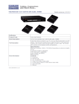
XTENDEX Features and Functions
1. Green LED- communication indicator- blinks when there is valid communication between the local and remote units.
2. Yellow LED- power indicator- illuminates when power has been supplied to the unit
3. Cat 5- RJ45 female- for connecting the CAT 5 cable
4. Video Connector- 15HD female- for connecting the local user's monitor
5. Audio Jack- 3.5mm stereo audio jack- for connecting to local speakers
6. Video Connector- blue 15HD male- for connecting to the video port on the CPU or KVM switch
7. Audio Plug- 3.5mm stereo audio plug- for connecting to CPU audio line out
8. Audio Jack- 3.5mm stereo audio jack- for connecting to remote speakers
9. 9VDC- 1.0A- connection jack for the AC adapter
10. Video Connector- 15HD female- for connecting the remote user's monitor
11. AC Adapter- to power the Remote and Local Units (1 for each required)
9 VDC
AC
ADAPTER
11

NTI VEEMUX AUDIO/VIDEO MATRIX SWITCH VIA CAT5
4
XTENDEX INSTALLATION
Audio Compatibility
• The audio input of the ST-C5VA-600 Audio/Video Extender is compatible with the following standard CPU audio outputs:
• Line out - typically lime green in color
• Speaker out- typically orange in color
• Headphone out- typically located on the CD-ROM (audio extension cable would be needed)
• The audio output of the ST-C5VA-600 Audio/Video Extender is compatible with self-powered stereo speakers.
The Local Unit
1. Plug the cables of the Local Unit into the back of the CPU. (See Fig. 1.)
a) Connect the blue 15HD cable end to the VGA port on the back of the CPU.
b) Connect the black 3.5mm stereo plug into the "line out", "spkr", or "headphones" jack on the
back of the CPU or other audio/video source (i.e. VCR, DVD player, etc.).
Notes:
If all 3 jacks are available, use the jack marked "line out".
The "line out" jack is typically lime green and may be marked with this symbol
The "spkr" jack is typically orange, and may be marked with this symbol
The "headphones" jack may be marked with this symbol
Figure 1- Connect the Local Unit to the CPU
(XTENDEX not included)

NTI VEEMUX AUDIO/VIDEO MATRIX SWITCH VIA CAT5
5
2. Make connections for a Local User (see Fig. 2)
a) Connect the cable from the local user's VGA monitor to the female 15HD port on the Local Unit.
b) Connect the cable from the local speakers into the 3.5mm jack on the local unit.
Figure 2- Connect Local User Components to Local Unit
3. Connect the CAT5 cable to the “Cat 5” port on the Local Unit. (See Fig. 2.) When properly inserted
the cable end should snap into place.
Note: If an RJ45 wall outlet is being used, connect the other end of the extension cable to the
RJ45 wall outlet.
WARNING: Never connect the ST-C5VA-600 Extender to an Ethernet card, Ethernet router, hub or switch or
other Ethernet RJ45 connector of an Ethernet device. Damage to devices connected to the Ethernet may result.
!

NTI VEEMUX AUDIO/VIDEO MATRIX SWITCH VIA CAT5
6
The Remote Unit
1. Position the Remote Unit such that the CAT5 cable, the monitor cable, speaker cable, and the AC
adapter power connector can each reach the Remote Unit comfortably.
2. Connect the monitor cable to the female 15HD video connector on the Remote Unit.
3. Connect the speakers to the 3.5mm jack on the Remote Unit (see Fig. 3).
Figure 3- Connect the Extended Components to the Remote Unit
4. Connect the CAT5 cable to the “Cat 5” port on the Remote Unit. (See Fig. 3.) When properly inserted the CAT5 cable end
should snap into place.
Note: If an RJ45 wall outlet is being used, connect the other end of the extension cable to the RJ45
wall outlet.
WARNING: Never connect the ST-C5VA-600 Extender to an Ethernet card, Ethernet router, hub or switch or
other Ethernet RJ45 connector of an Ethernet device. Damage to devices connected to the Ethernet may result.
!

NTI VEEMUX AUDIO/VIDEO MATRIX SWITCH VIA CAT5
7
Plug-in and Boot Up
1. Plug the power cord from the monitor into the power outlet.
2.
Connect each AC adapter power connector to the 9VDC ports on the Remote and Local Units. Make sure the power
connectors go into each port all the way. Plug each AC adapter into a power outlet. The yellow LED on the RJ45
connector of both the Remote and Local Units should illuminate, indicating that a proper power connection has been made to
them. (See Fig. 4.)
Figure 4- Connect the AC adapters
Note: The green LED on each RJ45 connector will blink anytime data traffic is passing between the Local and
Remote Units, indicating proper CAT5 cable connection and communication. (See Fig. 4)

NTI VEEMUX AUDIO/VIDEO MATRIX SWITCH VIA CAT5
8
VEEMUX INSTALLATION
1. Connect an ST-C5VA-600 Local Unit to an audio/video source as described on pages 4-5.
2. Connect a CAT5 cable (wired as specified on page 26) between the ST-C5VA-600 Local Unit and VEEMUX connector
"AV IN 1".
Figure 5- Attach ST-C5VA-600 Local Unit to VEEMUX
3. Connect a CAT5 cable (wired as specified on page 26) between an ST-C5VA-600 Remote Unit and VEEMUX connector
"AV OUT 1".
Note: Shielded CAT 5,5e, or 6 cable must be used to connect to LOCAL and REMOTE units in order to meet CE emission
requirements.
4. Connect a monitor and stereo speakers to the ST-C5VA-600 Remote Unit as described on page 6.
5. Connect the powercord as shown in Fig. 6.
Figure 6- Attach ST-C5VA-600 Remote Unit to VEEMUX

NTI VEEMUX AUDIO/VIDEO MATRIX SWITCH VIA CAT5
9
Note: This total length of CAT5 cable between the ST-C5VA-600 Remote and Local units cannot exceed 600 feet. (See
Fig. 9)
Figure 7- Maximum total CAT5 cable length cannot exceed 600 feet
6. To use the WEB Interface (page 15) , connect a CAT5 cable between the Local Network and the RJ45 connector on the
VEEMUX labeled ETHERNET. (See Fig. 8) This cable should be wired straight through between two RJ45 connectors (pin 1
to pin 1, etc.)
Figure 8- Connect VEEMUX to LAN
7. For direct connection of a user terminal, connect a null modem cable (specifications on page 25) between the user terminal
and the 9 pin DIN male connector on the VEEMUX labeled RS232. (See Fig. 9) The user terminal will control the VEEMUX via
the RS232 interface (page 13).
Figure 9- Connect user terminal to VEEMUX

NTI VEEMUX AUDIO/VIDEO MATRIX SWITCH VIA CAT5
10
USING THE VEEMUX SWITCH
The VEEMUX can be controlled by either of four methods:
• Using the keypad of the front panel interface
• Directly via an RS232 interface
• Remotely via web interface
• Remotely via telnet interface
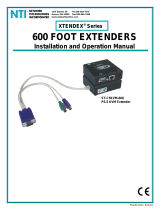
Front Panel Interface Overview
On the front panel is an 18 push-button keypad and LCD that enable the user to operate the switch and change settings.(See Fig.
10)
Figure 10- Front panel Interface LCD and keypad
After turning power ON, the LCD will show a start-up message for three seconds (see Fig. 11).
Figure 11- VEEMUX start-up message on LCD
During this time, the VEEMUX retrieves its switch settings from memory (the startup configuration is retrieved from stored
configuration 0). Pressing any buttons during this time will have no effect. After 3 seconds, the switch will function normally and
display the current configuration of connections. By default, the display will show all connections between Inputs and Outputs,
displaying 8 at a time from the first to the last. Each set of 8 connections will display for 2 seconds, and the cycle will repeat
indefinitely every 4 seconds.
Figure 12- Connections screen on LCD, displays 8 sets at a time
1 2 3
In
4
5
6
Out
78
9
0
*
Esc
Enter
Menu
IN: 1 2 3 4
OUT: 1 2 3 4
IN: 5 6 7 8
OUT: 5 6 7 8

NTI VEEMUX AUDIO/VIDEO MATRIX SWITCH VIA CAT5
11
Keypad Control
The front panel interface keypad and LCD enable the user to monitor switch status and route any user to any audio/video
source (INPUT) on the switch. Along with the routing of the INPUTS to the user devices (OUTPUTS) the keypad and LCD allow
the users to configure the RS-232 control interface and web server settings. The keypad buttons perform the following functions:
Key Action
ESC Cancel current action.
0 – 9 Used to enter numbers. ( n )
In The INPUT number can be entered (2 digits or 1 digit and ENTER) followed by the desired
OUTPUT to be connected to (2 digits or 1 digit and ENTER).
Out The OUTPUT number can be entered (2 digits or 1 digit and ENTER) followed by the
desired INPUT to be connected to (2 digits or 1 digit and ENTER).
ENTER Used to enter commands or values.
Used to scroll menu up
Used to scroll menu down
MENU The Configuration Menu is displayed.
*
Activate Memory Function- 10 memory locations (0 – 9), 0 is the power ON default.
- to Save current connections * - In - n (0-9) - ENTER
- to Recall connections * - Out - n (0-9) - ENTER
Also used to enter the periods in a IP address or Subnet Mask
Configuration Menu
By pressing the Menu key the display will show the following configuration menu:
Figure 13- Configuration menu on LCD
The configuration menu includes the following items:
1. Set Serial Address – allows the user to change the serial address of the switch
2. Set Serial Speed – allows the user to change the baud rate
3. Set IP address – allows the user to change the IP address allocated to the switch
4. Set Subnet Mask – allows the user to change the subnet mask
5. Set Default Gateway- allows the user to change the default gateway used
6. Set Wserver Timeout- allows the user to change the web server access timeout period
7. Adjust Contrast – allows the user to change the contrast of LCD
8. Video Adjustment – allows the user to force a video quality adjustment
9. Show Size – allows the user to see the dimensions of the switch and status of the webserver
Only 4 items are visible at a time. To navigate through configuration menu items, the user will use the and button from
keypad. The current item is highlighted. The user can select the current item by pressing the ENTER button. Alternatively, the
user can directly select any item, by pressing the corresponding number (1 to 9) from the keypad.

NTI VEEMUX AUDIO/VIDEO MATRIX SWITCH VIA CAT5
12
Set Serial Address
When selecting this menu item, the display shows the current serial address and the user is prompted to introduce a new
serial address. One or two digits can be entered followed by <Enter>. The display will prompt if the address is successfully
changed. Pressing <Esc> will cancel this command. The serial address is used by the RS232 line to send commands. Valid
addresses are between 1 and 99. The factory default address is 1.
Figure 14- Set Serial Address from LCD and keypad
Set Serial Speed
When selecting this menu item, the display shows the current serial speed (baud rate) and offers options to change to a
different speed:
Figure 15- Set baud rate from LCD and keypad
The current option is highlighted. Move the highlight (by using arrow keys) to the desired speed and press <Enter> to apply. An
alternative way is to press the number key that corresponds to desired speed (see Fig. 15).
To exit from this submenu, press <Esc>.
Available speeds are: 1200,2400,4800, and 9600 baud.
Factory default speed is 9600 baud.
Set IP Address
When selecting this menu item, the display shows the current IP address (default factory IP address is 192.168.1.1) and
prompts the user to enter a new IP address. A new IP address is entered using number keys and the <*> key for periods. The
user must press <Enter> to save the new IP address. If the new address is invalid, the user will be prompted, otherwise the
display will indicate that the address was successfully changed.
Figure 16- Set IP Address from LCD and keypad
Set Subnet Mask
When selecting this menu item, the display will show the current subnet mask. A new subnet mask is entered using
number keys and the <*> key for periods. The user must press <Enter> to save the new subnet mask. If the new subnet mask is
invalid, the user will be prompted, otherwise the display will indicate that the subnet mask was successfully changed.
The default subnet mask is 255.255.255.0. This does not need to be changed for VEEMUX to work. If deemed
necessary, the network administrator will change it .
Set Default Gateway
When selecting this menu item, the display will show the current default gateway. A new default gateway mask is
entered using number keys and the <*> key for periods. The user must press <Enter> to save the new default gateway. If the new
default gateway is invalid, the user will be prompted, otherwise the display will indicate that the default gateway mask was
successfully changed.
The factory set default gateway is 192.168.1.0. This does not need to be changed for VEEMUX to work. If deemed
necessary, the network administrator will change it .

NTI VEEMUX AUDIO/VIDEO MATRIX SWITCH VIA CAT5
13
Set Wserver Timeout
When selecting this menu item, the display shows the current webserver timeout period and offers optional values to
change it to.
Figure 17- Wserver Timeout Period
The currently selected value is highlighted. Move the highlight (using the arrow keys) to the desired timeout value and press
<Enter> to apply the value. An alternative method of selection is to press the number key that corresponds to the desired timeout
value.
Available timeout period values include: 1,5,10,15, or 30 minutes, and 1,2,5, or 8 hours. The default timeout period is 1 hour.
To exit, press <Esc>.
Adjust Contrast
When selecting this menu item, the display shows a scroll bar with the current position of the LCD display contrast value.
The user can change the contrast value using an arrow key from the Keypad. Pressing the up arrow will increase contrast while
pressing down arrow will decrease it. The scroll bar will move according to the contrast value and the effects of contrast
adjustments will be immediately visible on the LCD display.
Figure 18- Adjust LCD contrast
After adjusting the contrast the user can press <Enter> to store the new contrast value, or press <Esc> to return the contrast to
its original value.
Video Adjustment
This allows the user to force a connection to an output and initiate the video quality adjustment to assure the image on
the monitor is as clear as possible. This is useful when a CAT5 cable is changed without first switching the connection in the
VEEMUX. Otherwise an automatic video quality adjustment is made whenever a new connection (Input to Output) is established
and whenever VEEMUX is powered ON.
Show Size
This menu item allows the users to see the number of inputs and outputs available for the switch and the status of the
webserver.
Displaying Audio Level (Digital VU-Meter)
To display the dynamic audio level (volume) of one of the outputs, the user should press <Esc> from the normal display
mode (connection status). The following window will display the decibel level of left and right audio channels. The rightmost
gradation on the scale corresponds to 0dB, and the leftmost -96dB.
Figure 19- View Output audio level
To display the audio output level of a different Output port, type the number of the desired Output (1 or 2 digits) and press
<Enter>.

NTI VEEMUX AUDIO/VIDEO MATRIX SWITCH VIA CAT5
14
This function is particularly useful to determine if a lack of sound from speakers is due to failed speakers, or lack of audio signal
through the VEEMUX. If no signal is seen in this display, check all connections between the audio source, the XTENDEX, and
the respective Input port on the VEEMUX.
Pressing <Esc> again will return to the connections display.
RS232 Interface
A user may control the VEEMUX using an RS232 interface by connecting a PC to the 9 pin DIN male connector on the VEEMUX
labeled "RS232". Using a program such as HyperTerminal or the Matrix Switcher's Control Program (page 15), the VEEMUX
can be setup and controlled.
When using HyperTerminal (or a similar program), configured at the same baud rate as in the VEEMUX (default is 9,600), 8 bits,
no parity, no flow control, the VEEMUX can be controlled by sending the commands in the following chart, where:
SW = the Switch Serial Address
<CR> = the Carriage Return character
IP = the input port
OP = the output port
ip = the IP address
Command Answer Description
CS SW,IP,OP *<CR> Connect One Input (Audio/Video Source) to Output (User Port)
CA SW,IP *<CR> Connect All Outputs To Input
RO SW,OP *<CR>IP<CR> Read Connection For Output
CC SW,xx *<CR>xx<CR>
Save Matrix Connections Into Memory Bank xx
xx= 00-09
RC SW,xx *<CR>xx<CR>
Restore Matrix Connections From Memory Bank xx
Xx=00-09
CB 00,nn none
Change baud rate of serial line, nn=12(00),24(00),48(00),96(00)
Factory default is 9,600
RV SW,00 *<CR>string\0<CR> Read NTI Version String
RU SW *<CR>IP,OP<CR> Read Unit Size
EA SW,ip *<CR>
Set the IP address, ip is in xxx.xxx.xxx.xxx format,
number of digits is minimum 1 and maximum 3 for each field
Leading zeroes are accepted
EM SW,ip *<CR>
Set the Subnet mask, ip is in xxx.xxx.xxx.xxx format,
number of digits is minimum 1 and maximum 3 for each field.
Leading zeroes are accepted
EG SW,ip *<CR>
Set the default gateway, ip is in xxx.xxx.xxx.xxx format,
number of digits is minimum 1 and maximum 3 for each field
Leading zeroes are accepted
ET SW,timeout *<CR>
Set the website timeout; timeout = numeric string of timeout in
seconds.
Values: 60, 300, 600, 900, 1800, 3600, 7200, 18000, 28800
RA SW * <CR>ip<CR>
Read the IP address, ip is in xxx.xxx.xxx.xxx format,
number of digits is minimum 1 and maximum 3 for each field
Leading zeroes are accepted
RM SW * <CR>ip<CR>
Read the Subnet mask, ip is in xxx.xxx.xxx.xxx format,
number of digits is minimum 1 and maximum 3 for each field
Leading zeroes are accepted
RG SW * <CR>ip<CR>
Read the default gateway, ip is in xxx.xxx.xxx.xxx format,
number of digits is minimum 1 and maximum 3 for each field
Leading zeroes are accepted
RT SW * <CR>timeout<CR>
Read the website timeout; timeout = numeric string of timeout in
seconds.
Values: 60, 300, 600, 900, 1800, 3600, 7200, 18000, 28800
If the first field is not a known command (as listed above) or SW field is different from the serial address programmed in the switch
memory, the command will be ignored. If the SW field corresponds to the serial address, but the syntax is wrong after this field,
the switch will answer with ?<CR>.

NTI VEEMUX AUDIO/VIDEO MATRIX SWITCH VIA CAT5
15
Matrix Switcher's Control Program For Windows 9X, NT, 2000 and XP
The Matrix Switcher's Control Program is an easy and powerful graphical program that controls NTI matrix switches through an
RS232 interface from an attached PC. The Matrix Switcher's Control Program is included on the CD packaged with the
VEEMUX. The Matrix Switcher's Control Program is downloaded by clicking on the link "Download Matrix Switcher's Control
Program".
To install the Matrix Switcher's Control Program after downloading
1.
Locate the Setup.exe in the directory the program was downloaded to and double-click on it
2.
Follow the instructions on the screen
The Matrix Switcher's Control Program performs best on monitors set to a screen resolution of at least 800 X 600. Instruction for
using the Matrix Switcher’s Control Program is available by opening "MSCP Help" in the "NTI" program group once the program
has been installed and is open on the screen.
To open "MSCP Help" from the Windows desktop
1. Click on START
2. Click on PROGRAMS
3. Click on NTI
4. Click on MSCP Help

NTI VEEMUX AUDIO/VIDEO MATRIX SWITCH VIA CAT5
16
Telnet Interface
The Telnet Interface enables the user to control the switch using telnet client through an Ethernet connection. The telnet server
listens on port 2000. To access the telnet interface, using the current IP address type the following in a command shell:
telnet 192.168.1.1 2000
The VEEMUX will prompt the user for a password. The user must enter the password followed by <Enter>.
The default factory password is "admin".
With a proper password sent the VEEMUX will respond with:
Password Successful
Connection Established
The following commands are now available:
Command Reply Description
H(elp) or
h(elp)
Displays the list of
commands
Help
<Ctrl>-<X>
(see note 4 below)
Good Bye.
Connection to host lost.
Quit telnet session
CS nn,mm *<CR> Connect one Output Port (nn) To one Input Port (mm)
CA nn *<CR> Connect All Outputs To Input
RO nn *<CR>mm<CR>
Read Connection For Output.
Returns the number of the input (mm) connected to output nn
CC nn *<CR>nn<CR>
Save Matrix Connections Into Memory Bank nn
nn should be between 00 and 09
RC nn *<CR>nn<CR>
Restore Matrix Connections From Memory Bank nn
nn should be between 00 and 09
CB nn *<CR>
Change baud rate of serial line, nn=12(00),24(00),48(00),96(00)
Factory default is 9,600.
RV 00 *<CR>string\0<CR> Read NTI Version String
RU *<CR>nn,mm<CR>
Read Unit Size
Returns the number of inputs(nn) and the number of outputs (mm)
CP
User is prompted to
introduce the password
twice
Change password
Notes:
1. The commands must be typed exactly as shown in the chart. The commands are case sensitive.
2. If a mistake is made, the user must backspace to the beginning and completely retype the command.
3. If a command is sent that the VEEMUX does not recognize or exceeds the configuration of the switch, the reply
"?" may be received. Check the command syntax and try again.
4. To quit the telnet session, press the keyboard keys <Ctrl><X> .
/