ABB Relion RES670 User manual

Category
Measuring, testing & control
Type
User manual

This manual is also suitable for

—
RELION® 670 SERIES
Phasor measurement unit RES670
Version 2.1
Product guide
Contents
1. Application............................................................................. 3
2. Available functions...............................................................8
3. Differential protection.......................................................17
4. Impedance protection.......................................................17
5. Wide area measurement system....................................18
6. Current protection............................................................. 18
7. Voltage protection............................................................. 19
8. Frequency protection....................................................... 20
9. Multipurpose protection..................................................20
10. Secondary system supervision...................................... 21
11. Control................................................................................. 21
12. Logic.....................................................................................22
13. Monitoring..........................................................................24
14. Metering..............................................................................26
15. Human machine interface..............................................26
16. Basic IED functions...........................................................27
17. Station communication ................................................. 27
18. Remote communication................................................. 28
19. Hardware description......................................................28
20. Connection diagrams...................................................... 31
21. Technical data....................................................................32
22. Ordering for customized IED.........................................79
23. Ordering for pre-configured IED..................................88
24. Ordering for Accessories................................................93
Disclaimer
The information in this document is subject to change without notice and should not be construed as a commitment by ABB. ABB assumes no
responsibility for any errors that may appear in this document. Drawings and diagrams are not binding.
© Copyright 2015 ABB. All rights reserved.
Trademarks
ABB and Relion are registered trademarks of the ABB Group. All other brand or product names mentioned in this document may be trademarks or
registered trademarks of their respective holders.
Phasor measurement unit RES670 2.1 IEC
1MRK 511 367-BEN D
2 ABB
1. Application
GUID-CF75762E-73C1-40AF-8D6F-6EC3D8395982 v3
RES670 is a Phasor Measurement Unit (PMU) that
provides power system AC voltages and currents as
phasors for all voltage levels in power system networks.
Phasors are provided as real and imaginary or as
magnitude and phase angle. The reference for the phase
angle is the NavStar Global Positioning System – GPS
that also supplies highly accurate time and date. The
measured data in each PMU is time-synchronized via
Global Positioning System (GPS) receivers – with an
accuracy of one microsecond – and transmitted to
Phasor Data Concentrators (every 100 milliseconds for
example). The accurate time tagging of measurements
taken at different geographical locations makes it
possible to derive the synchronized phasor quantities
(synchrophasors). Based on synchrophasors, a number
of power system applications are available.
The PMUs are installed at substation level, and can be
connected directly to current and voltage transformers
within the substations. Each RES670 can have its own
antenna and GPS system for time synchronization
purposes or it can receive the IRIG-B signal from an
external GPS-based clock. It is also possible to have
both direct GPS and IRIG-B connection to provide time
synchronization redundancy for the PMU. RES670
streams out its synchrophasor data according to IEEE
C37.118 and/or IEEE 1344 standards for synchrophasor
data streaming and with user-selectable reporting rates.
RES670 supports reporting rates of 10, 25, 50, 100, and
200 frames per second for 50Hz system (or 10, 12, 15, 30,
60, 120, and 240 frames per second for 60Hz system).
Each RES670 can communicate its synchrophasor data
to up to eight independent clients over TCP and/or six
independent UDP channels (unicast/multicast),
simultaneously. More information is available in RES670
Application Manual under Wide Area Measurement
System section.
In addition to the synchrophasor communication
standard (IEEE 1344, IEEE C37.118), RES670 is also
compliant to IEC 61850-8-1 standard for integration to
substation automation systems and exchange of GOOSE
messages, when necessary. RES670 is able to
communicate over IEC 62439-3 PRP for redundant
station bus communication for both IEEE C37.118 and
IEC 61850-8-1, simultaneously.
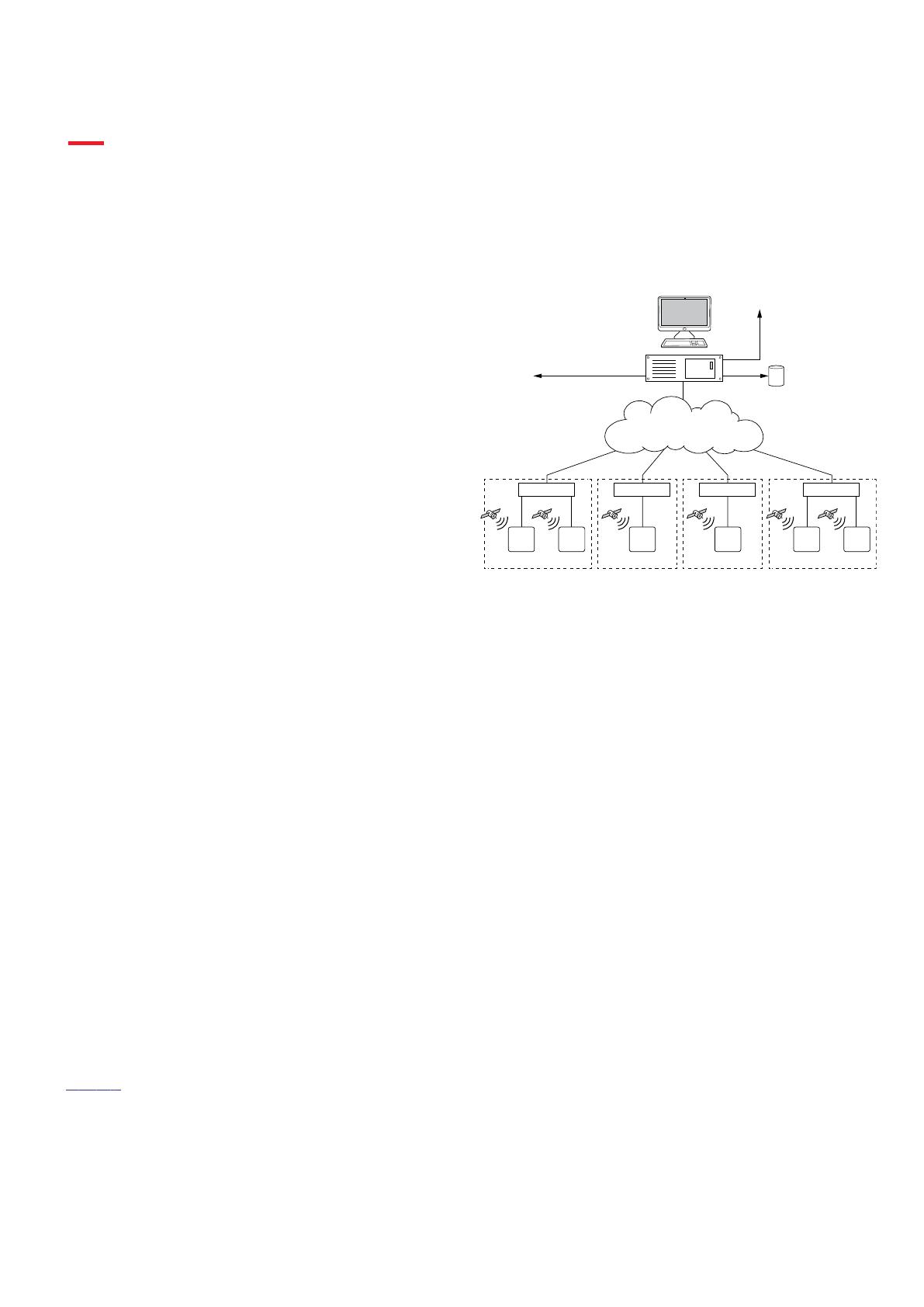
Figure 1 shows an example of a system architecture for a
Wide Area Monitoring System (WAMS). PMUs are the
building blocks for a WAMS. The architecture of a WAMS
consists of the following main components:
•
PMU Phasor Measurement Unit, including all
accessories for time synchronization
• TCP/IP and/or UDP/IP communication network infra-
structure
• PDC Phasor Data Concentrator, including wide area
applications
Substation 1
Visualization
(Applications)
Interface to
SCADA / EMS
Data Storage and Event
Driven Archiving
Gateway to other Utilities
IEC140000114-1-en.ai
Phasor Data Concentrator
PDC
Substation 2 Substation 3 Substation N
Router Router Router Router
TCP/IP communication network
PMU protocol IEEE C37.118
PMU PMU PMU PMUPMU PMU
GPS GPS GPSGPS GPS GPS
IEC140000114 V1 EN-US
Figure 1. Wide Area Monitoring System architecture — overview
A Wide Area Monitoring System collects, stores,
transmits and provides ways to analyze critical data
from key points across the power networks and over
large geographical areas. The architecture of the WAMS
can provide a scalable solution, from small installations
for data collection and basic visualization (PDC) to
larger systems with intelligent monitoring using wide
area applications. The Wide Area Monitoring
applications are designed to detect abnormal system
conditions and evaluate large area disturbances in order
to preserve system integrity and maintain acceptable
power system performance.
The WAMS is configured in a way to acquire
synchrophasor data from several PMUs. Based on the
data collected in the PDCs, WAMS is able to present the
state of the grid to the power system operator, and to
provide monitoring of the power system based on real-
time measurements and the results of on-line
applications. In addition, the data available from PDCs
enables off-line analysis of the power system for post-
disturbance assessments. It is possible to communicate
the PMU measurements and the results of the advanced
applications to SCADA/EMS systems as a way to
improve the supervision of the system, providing the
operator with a clear indication how likely the system is
to collapse, thus giving the possibility to react in time.
Forcing of binary inputs and outputs is a convenient way
to test wiring in substations as well as testing
configuration logic in the IEDs. Basically it means that all
Phasor measurement unit RES670 2.1 IEC
1MRK 511 367-BEN D
Issued: March 2019
Revision: D
ABB 3
binary inputs and outputs on the IED I/O modules (BOM,
BIM, IOM & SOM) can be forced to arbitrary values.
Central Account Management is an authentication
infrastructure that offers a secure solution for enforcing
access control to IEDs and other systems within a
substation. This incorporates management of user
accounts, roles and certificates and the distribution of
such, a procedure completely transparent to the user.
The Flexible Product Naming allows the customer to use
an IED-vendor independent 61850 model of the IED. This
customer model will be exposed in all IEC 61850
communication, but all other aspects of the IED will
remain unchanged (e.g., names on the local HMI and
names in the tools). This offers significant flexibility to
adapt the IED to the customers system and standard
solution
Description of configuration A20
GUID-DE587E43-5AB7-4B08-A7A2-051F0A050D83 v3
The configuration of the IED is shown in
figure 2.
RES670 A20 configuration is applicable for a typical
single busbar single breaker arrangement monitoring up
to three bays. RES670 A20 is delivered in 1/2, 3/4 and
full (1/1)19" rack casing. For this application 12 analog
inputs are used, thus only one transformer module
(TRM) with 12 analog inputs (9I+3U) is available in A20
standard configuration. As shown in
figure 2, RES670
A20 configuration as a PMU is measuring one 3-phase
voltage of the busbar and three 3-phase currents of bays
1 to 3. There are two instances of PMU reporting
functionality available in A20 configuration, meaning
two independent IEEE C37.118/1344 data streams. In the
standard A20 configuration, each instance of PMU, in
addition to frequency-deviation and rate-of-change-of-
frequency data, is reporting 16 synchrophasors over
IEEE C37.118/1344; that is four 3-phase synchrophasors
and 12 single phase synchrophasors in each data stream
corresponding to the AC voltage and current
measurements.
In addition, each data stream includes 8 analog and 8
binary reporting channels over IEEE C37.118/1344 in the
standard configuration. The number of analog and
binary reporting channels can be extended to maximum
24 channels per PMU instance (on each data stream) on
request. This can be done when ordering the RES670 A20
configuration. In the standard A20 configuration, the
analog reporting channels are used for reporting P and
Q measurements from each bay over IEEE C37.118/1344.
In addition to the binary reporting channels, there are 4
trigger bits (FREQTRIG, DFDTTRIG, OCTRIG and UVTRIG)
available per PMU instance, which are used to report the
existing protection function triggers over IEEE
C37.118/1344.
The main functionality of the RES670 is synchrophasor
reporting or PMU functionality. In addition, this
configuration also includes general back-up protection
functions which are mainly intended for alarm purposes.
Available protection functions in standard A20
configuration are Overvoltage, Undervoltage,
Overfrequency, Underfrequency and Rate-of-change
frequency.
Measuring functions for S, P, Q, I, U, PF, f are available
for local presentation on the local HMI and remote
presentation via IEEE C37.118/1344 and/or via IEC
61850. The calibration parameters on the measurement
function allows calibration at site to very high accuracy.
As shown in
figure 2, there are optional functions such
as Earth fault protection (EF4 PTOC), Overcurrent
protection (OC4 PTOC), Under/Over power protection
(GUPPDUP, GOPPDOP), etc. which can be added per
request. RES670 A20 function library also includes
additional functions, which are available but not
configured. Note that RES670 A20 must be reconfigured
if any additional functions are used.
Phasor measurement unit RES670 2.1 IEC
1MRK 511 367-BEN D
4 ABB
SA PTUF
81U f<
SA PTOF
81 f>
UV2 PTUV
27 2(3U<)
V MMXU
MET U
RES670 A20 – Phasor Measurement Unit, 3 bays, single busbar,
12AI (9I+3U)
DRP RDRE
DFR/SER DR
WA1_VT
CCS SPVC
87 INd/I
OOS PPAM
78 Ucos
Other Functions available from the function library
Optional Functions
SDE PSDE
67N IN>
Q CBAY
3 Control
S SIMG
63
S SIML
71
WA1
CV MMXN
MET P/Q
SA PFRC
81 df/dt
OV2 PTOV
59 2(3U>)
V MSQI
MET Usqi
CV MMXN
MET P/Q
CV MMXN
MET P/Q
C MMXU
MET I
C MMXU
MET I
C MMXU
MET I
C MSQI
MET Isqi
C MSQI
MET Isqi
C MSQI
MET Isqi
PMU REP
PMU REP
BAY01_CT
BAY03_CT
BAY02_CT
IEEE Std 1344
IEEE Std C37.118
Phasor
data
IEEE Std 1344
IEEE Std C37.118
ETP MMTR
MET W/Varh
SMP PTRC
94 1? 0
VN MMXU
MET UN
CV GAPC
2(I>/U<)
EF4 PTOC
51N_67N
4(IN>)
FUF SPVC
U>/I<
GOP PDOP
32 P>
GUP PDUP
37 P<
NS4 PTOC
46I2 4(I2>)
OC4 PTOC
51_67 4(3I>)
ZM RPSB
68 Zpsb
IEC140000122-1-en.vsd
IEC140000122 V1 EN-US
Figure 2. Configuration diagram for configuration A20
Phasor measurement unit RES670 2.1 IEC
1MRK 511 367-BEN D
ABB 5
Description of configuration B20
GUID-E8A586F6-E450-4B5E-AF00-1DC9A197A2A6 v3
The configuration of the IED is shown in figure 3.
RES670 B20 configuration is applicable for a typical
double busbar single breaker arrangement monitoring
up to six bays. RES670 B20 is delivered in ¾, and full
(1/1)19" rack casing. For this application 24 analog
inputs are used, thus two transformer modules (TRM)
with 12 analog inputs (9I+3U) per TRM are available in
B20 standard configuration. As shown in
figure 3,
RES670 B20 configuration as a PMU is measuring two 3-
phase voltages of the busbars and six 3-phase currents
of bays 1 to 6. There are two instances of PMU reporting
functionality available in B20 configuration, meaning
two independent IEEE C37.118/1344 data streams. Each
instance of PMU is reporting frequency-deviation and
rate-of-change-of-frequency data. In the standard B20
configuration, in addition to frequency data, first
instance of PMU (first data stream) is reporting 32
synchrophasors over IEEE C37.118/1344; that is eight 3-
phase synchrophasors and 24 single phase
synchrophasors corresponding to the AC voltage and
current measurements. Second instance of PMU (second
data stream) is reporting 16 synchrophasors over IEEE
C37.118/1344; that is four 3-phase synchrophasors and
12 single phase synchrophasors corresponding to the AC
voltage and current measurements. The number of
synchrophasor reporting channels on second instance of
PMU can be extended to 32 channels per request. This
can be done when ordering the RES670 B20
configuration.
In addition, each data stream includes 16 analog and 16
binary reporting channels over IEEE C37.118/1344 in the
standard configuration. The number of analog and
binary reporting channels can be extended to maximum
24 channels per PMU instance (on each data stream) on
request. This can be done when ordering the RES670 B20
configuration. In the standard B20 configuration the
analog reporting channels are used for reporting P and
Q measurements from each bay over IEEE C37.118/1344.
In addition to the binary reporting channels there are 4
trigger bits (FREQTRIG, DFDTTRIG, OCTRIG, and UVTRIG)
available per PMU instance which are used to report the
existing protection function triggers over IEEE
C37.118/1344.
The main functionality of the RES670 is synchrophasor
reporting or PMU functionality. In addition, this
configuration also includes general back-up protection
functions which are mainly intended for alarm purposes.
Available protection functions in standard B20
configuration are Over Voltage, Under Voltage, Over
Frequency, Under Frequency and Rate of Change of
Frequency.
Measuring functions for S, P, Q, I, U, PF, f are available
for local presentation on the local HMI and remote
presentation via IEEE C37.118/1344 and/or via IEC
61850. The calibration parameters on the measurement
function allows calibration at site to very high accuracy.
As shown in
figure 3, there are optional functions such
as Earth fault protection (EF4 PTOC), Overcurrent
protection (OC4 PTOC), Under/Over power protection
(GUPPDUP, GOPPDOP), etc. which can be added per
request. RES670 B20 function library also includes
additional functions which are available but not
configured. Note that RES670 B20 must be reconfigured
if any additional functions are used.
Phasor measurement unit RES670 2.1 IEC
1MRK 511 367-BEN D
6 ABB
SA PTUF
81U f<
SA PTUF
81 f<
SA PTOF
81O f>
SA PTOF
81 f>
UV2 PTUV
27 2(3U<)
OV2 PTOV
59 2(3U>)
V MSQI
MET Usqi
V MMXU
MET U
RES670 B20 – Phasor Measurement Unit, 6 bays, double busbar,
24AI (9I+3U, 9I+3U)
DRP RDRE
DFR/SER DR
WA1_VT
C MMXU
MET I
C MSQI
MET Isqi
CCS SPVC
87 INd/I
OOS PPAM
78 Ucos
Other Functions available from the function library
Optional Functions
SDE PSDE
67N IN>
Q CBAY
3 Control
S SIMG
63
S SIML
71
WA1
WA2
CV MMXN
MET P/Q
SA PFRC
81 df/dt
SA PFRC
81 df/dt
WA2_VT
UV2 PTUV
27 2(3U<)
OV2 PTOV
59 2(3U>)
V MMXU
MET U
V MSQI
MET Usqi
CV MMXN
MET P/Q
CV MMXN
MET P/Q
CV MMXN
MET P/Q
CV MMXN
MET P/Q
CV MMXN
MET P/Q
C MMXU
MET I
C MMXU
MET I
C MMXU
MET I
C MMXU
MET I
C MMXU
MET I
C MSQI
MET Isqi
C MSQI
MET Isqi
C MSQI
MET Isqi
C MSQI
MET Isqi
C MSQI
MET Isqi
Busbar
Voltage
Selection
PMU REP
PMU REP
BAY01_CT
BAY04_CT
BAY05_CT
BAY06_CT
BAY03_CT
BAY02_CT
IEEE Std 1344
IEEE Std C37.118
Phasor
data
IEEE Std 1344
IEEE Std C37.118
ETP MMTR
MET W/Varh
SMP PTRC
94 1? 0
VN MMXU
MET UN
CV GAPC
2(I>/U<)
EF4 PTOC
51N_67N
4(IN>)
FUF SPVC
U>/I<
GOP PDOP
32 P>
GUP PDUP
37 P<
NS4 PTOC
46I2 4(I2>)
OC4 PTOC
51_67 4(3I>)
ZM RPSB
68 Zpsb
IEC140000123-1-en.vsd
IEC140000123 V1 EN-US
Figure 3. Configuration diagram for configuration B20
Phasor measurement unit RES670 2.1 IEC
1MRK 511 367-BEN D
ABB 7
2. Available functions
Wide area measurement functions
GUID-8A114D7E-8D1A-46ED-A928-B819ED163A52 v3
IEC 61850 ANSI Function description Phasor
Measurement Unit
Phasor
measurement unit
RES670
(Customized)
RES670 (A20)
RES670 (B20)
PMUCONF Configuration parameters for IEEE1344 and C37.118
protocol
1 1 1
PMUREPORT Protocol reporting via IEEE1344 and C37.118 1–2 2 2
PHASORREPORT1 Protocol reporting of phasor data via IEEE 1344 and
C37.118, phasors 1-8
1-2 2 2
PHASORREPORT2 Protocol reporting of phasor data via IEEE 1344 and
C37.118, phasors 9-16
0-2 2 2
PHASORREPORT3 Protocol reporting of phasor data via IEEE 1344 and
C37.118, phasors 17-24
0-2 1B,
1-P11
PHASORREPORT4 Protocol reporting of phasor data via IEEE 1344 and
C37.118, phasors 25-32
0-2 1B,
1-P11
ANALOGREPORT1 Protocol reporting of analog data via IEEE 1344 and
C37.118, analogs 1-8
0-2 2 2
ANALOGREPORT2 Protocol reporting of analog data via IEEE 1344 and
C37.118, analogs 9-16
0-2 1-P12/
2-P13
2
ANALOGREPORT3 Protocol reporting of analog data via IEEE 1344 and
C37.118, analogs 17-24
0-2 1-P12/
2-P13
1-P14/
2-P15
BINARYREPORT1 Protocol reporting of binary data via IEEE 1344 and
C37.118, binary 1-8
0-2 2 2
BINARYREPORT2 Protocol reporting of binary data via IEEE 1344 and
C37.118, binary 9-16
0-2 1-P16/
2-P17
2
BINARYREPORT3 Protocol reporting of binary data via IEEE 1344 and
C37.118, binary 17-24
0-2 1-P16/
2-P17
1-P18/
2-P19
PMUSTATUS Diagnostics for C37.118 2011 and IEEE1344 protocol 1 1 1
Phasor measurement unit RES670 2.1 IEC
1MRK 511 367-BEN D
8 ABB
Back-up protection functions
GUID-A8D0852F-807F-4442-8730-E44808E194F0 v10.1.1
IEC 61850 ANSI Function description Phasor measurement unit
RES670
(Customized)
RES670 (A20)
RES670 (B20)
Impedance protection
ZMRPSB 68 Power swing detection 0-1 1-B23 1-B23
OOSPPAM 78 Out-of-step protection 0-2 2-B23 2-B23
Current protection
OC4PTOC
51_67
1)
Four step phase overcurrent protection 0-6 3-C26 6-C27
EF4PTOC 51N
67N
2)
Four step residual overcurrent protection 0-6 3–C26 6–C27
NS4PTOC 46I2 Four step directional negative phase sequence overcurrent
protection
0-6 3-C26 6-C27
SDEPSDE 67N Sensitive directional residual overcurrent and power
protection
0-6 3-C26 6-C27
LCPTTR 26 Thermal overload protection, one time constant, Celsius 0–6
LFPTTR 26 Thermal overload protection, one time constant, Fahrenheit 0–6
GUPPDUP 37 Directional underpower protection 0-4 3C-18 4C-25
GOPPDOP 32 Directional overpower protection 0-4 3C-18 4C-25
Voltage protection
UV2PTUV 27 Two step undervoltage protection 0-4 1 2
OV2PTOV 59 Two step overvoltage protection 0-4 1 2
Frequency protection
SAPTUF 81 Underfrequency protection 0-6 1 2
SAPTOF 81 Overfrequency protection 0-6 1 2
SAPFRC 81 Rate-of-change frequency protection 0-6 1 2
FTAQFVR 81A Frequency time accumulation protection 0-4
Multipurpose protection
CVGAPC General current and voltage protection 0-8 4–F01 6–F02
SMAIHPAC Multipurpose filter 0-6
1) 67 requires voltage
2) 67N requires voltage
Phasor measurement unit RES670 2.1 IEC
1MRK 511 367-BEN D
ABB 9
Control and monitoring functions
GUID-E3777F16-0B76-4157-A3BF-0B6B978863DE v12.1.1
IEC 61850 ANSI Function description Phasor
measurement
unit
Phasor
measurement
unit
RES670
RES670 (A20)
RES670 (B20)
Control
QCBAY Apparatus control 1 1 1
LOCREM Handling of LRswitch positions 1 1 1
LOCREMCTRL LHMI control of PSTO 1 1 1
SLGAPC Logic rotating switch for function selection and LHMI presentation 15 15 15
VSGAPC Selector mini switch 20 20 20
DPGAPC Generic communication function for Double Point indication 16 16 16
SPC8GAPC Single point generic control 8 signals 5 5 5
AUTOBITS AutomationBits, command function for DNP3.0 3 3 3
SINGLECMD Single command, 16 signals 4
I103CMD Function commands for IEC 60870-5-103 1 1 1
I103GENCMD Function commands generic for IEC 60870-5-103 50 50 50
I103POSCMD IED commands with position and select for IEC 60870-5-103 50 50 50
I103POSCMDV IED direct commands with position for IEC 60870-5-103 50 50 50
I103IEDCMD IED commands for IEC 60870-5-103 1 1 1
I103USRCMD Function commands user defined for IEC 60870-5-103 4 4 4
Secondary
system
supervision
CCSSPVC 87 Current circuit supervision 0–5 3–G01 5–G02
FUFSPVC Fuse failure supervision 0-4 1–G01 2–G02
Logic
SMPPTRC 94 Tripping logic 6 6 6
TMAGAPC Trip matrix logic 12 12 12
ALMCALH Logic for group alarm 5 5 5
WRNCALH Logic for group warning 5 5 5
INDCALH Logic for group indication 5 5 5
AND, GATE, INV,
LLD, OR,
PULSETIMER,
RSMEMORY,
SRMEMORY,
TIMERSET, XOR
Basic configurable logic blocks (see Table 1) 40-280 40–
280
40–
280
Phasor measurement unit RES670 2.1 IEC
1MRK 511 367-BEN D
10 ABB
IEC 61850 ANSI Function description Phasor
measurement
unit
Phasor
measurement
unit
RES670
RES670 (A20)
RES670 (B20)
ANDQT,
INDCOMBSPQT,
INDEXTSPQT,
INVALIDQT,
INVERTERQT,
ORQT,
PULSETIMERQT,
RSMEMORYQT,
SRMEMORYQT,
TIMERSETQT,
XORQT
Configurable logic blocks Q/T (see Table 2) 0–1
AND, GATE, INV,
LLD, OR,
PULSETIMER,
SLGAPC,
SRMEMORY,
TIMERSET,
VSGAPC, XOR
Extension logic package (see Table 3) 0–1
FXDSIGN Fixed signal function block 1 1 1
B16I Boolean 16 to Integer conversion 18 18 18
BTIGAPC Boolean 16 to Integer conversion with Logic Node representation 16 16 16
IB16 Integer to Boolean 16 conversion 18 18 18
ITBGAPC Integer to Boolean 16 conversion with Logic Node representation 16 16 16
TEIGAPC Elapsed time integrator with limit transgression and overflow
supervision
12 12 12
INTCOMP Comparator for integer inputs 12 12 12
REALCOMP Comparator for real inputs 12 12 12
Monitoring
CVMMXN,
VMMXU, CMSQI,
VMSQI, VNMMXU
Measurements 6 6 6
CMMXU Measurements 10 10 10
AISVBAS Function block for service value presentation of secondary analog
inputs
1 1 1
EVENT Event function 20 20 20
DRPRDRE,
A1RADR-A4RADR,
B1RBDR-B8RBDR
Disturbance report 1 1 1
SPGAPC Generic communication function for Single Point indication 64 64 64
SP16GAPC Generic communication function for Single Point indication 16 inputs 16 16 16
MVGAPC Generic communication function for Measured Value 24 24 24
BINSTATREP Logical signal status report 3 3 3
Phasor measurement unit RES670 2.1 IEC
1MRK 511 367-BEN D
ABB 11
IEC 61850 ANSI Function description Phasor
measurement
unit
Phasor
measurement
unit
RES670
RES670 (A20)
RES670 (B20)
RANGE_XP Measured value expander block 66 66 66
SSIMG 63 Gas medium supervision 21 21 21
SSIML 71 Liquid medium supervision 3 3 3
SSCBR Circuit breaker monitoring 0-18 9-M17 18-
M16
I103MEAS Measurands for IEC 60870-5-103 1 1 1
I103MEASUSR Measurands user defined signals for IEC 60870-5-103 3 3 3
I103AR Function status auto-recloser for IEC 60870-5-103 1 1 1
I103EF Function status earth-fault for IEC 60870-5-103 1 1 1
I103FLTPROT Function status fault protection for IEC 60870-5-103 1 1 1
I103IED IED status for IEC 60870-5-103 1 1 1
I103SUPERV Supervison status for IEC 60870-5-103 1 1 1
I103USRDEF Status for user defined signals for IEC 60870-5-103 20 20 20
L4UFCNT Event counter with limit supervision 30 30
TEILGAPC Running hour-meter 6 6
6
Metering
PCFCNT Pulse-counter logic 16 16 16
ETPMMTR Function for energy calculation and demand handling 6 6 6
Table 1. Total number of instances for basic configurable logic blocks
Basic configurable logic block
Total number of instances
AND 280
GATE 40
INV 420
LLD 40
OR 280
PULSETIMER 40
RSMEMORY 40
SRMEMORY 40
TIMERSET 60
XOR 40
Phasor measurement unit RES670 2.1 IEC
1MRK 511 367-BEN D
12 ABB
Table 2. Total number of instances for configurable logic blocks Q/T
Configurable logic blocks Q/T Total number of instances
ANDQT 120
INDCOMBSPQT 20
INDEXTSPQT 20
INVALIDQT 22
INVERTERQT 120
ORQT 120
PULSETIMERQT 40
RSMEMORYQT 40
SRMEMORYQT 40
TIMERSETQT 40
XORQT 40
Table 3. Total number of instances for extended logic package
Extended configurable logic block Total number of instances
AND 180
GATE 49
INV 180
LLD 49
OR 180
PULSETIMER 59
SLGAPC 74
SRMEMORY 110
TIMERSET 49
VSGAPC 130
XOR 49
Phasor measurement unit RES670 2.1 IEC
1MRK 511 367-BEN D
ABB 13
Communication
GUID-5F144B53-B9A7-4173-80CF-CD4C84579CB5 v12.1.1
IEC 61850 ANSI Function description Phasor measurement unit
RES670
(Customized)
RES670 (A20)
RES670 (B20)
Station communication
LONSPA, SPA SPA communication protocol 1 1 1
ADE LON communication protocol 1 1 1
HORZCOMM Network variables via LON 1 1 1
PROTOCOL Operation selection between SPA and IEC 60870-5-103 for SLM 1 1 1
RS485PROT Operation selection for RS485 1 1 1
RS485GEN RS485 1 1 1
DNPGEN DNP3.0 communication general protocol 1 1 1
DNPGENTCP DNP3.0 communication general TCP protocol 1 1 1
CHSERRS485 DNP3.0 for EIA-485 communication protocol 1 1 1
CH1TCP, CH2TCP,
CH3TCP, CH4TCP
DNP3.0 for TCP/IP communication protocol 1 1 1
CHSEROPT DNP3.0 for TCP/IP and EIA-485 communication protocol 1 1 1
MST1TCP,
MST2TCP,
MST3TCP,
MST4TCP
DNP3.0 for serial communication protocol 1 1 1
DNPFREC DNP3.0 fault records for TCP/IP and EIA-485 communication
protocol
1 1 1
IEC 61850-8-1 Parameter setting function for IEC 61850 1 1 1
GOOSEINTLKRCV Horizontal communication via GOOSE for interlocking 59 59 59
GOOSEBINRCV GOOSE binary receive 16 16 16
GOOSEDPRCV GOOSE function block to receive a double point value 64 64 64
GOOSEINTRCV GOOSE function block to receive an integer value 32 32 32
GOOSEMVRCV GOOSE function block to receive a measurand value 60 60 60
GOOSESPRCV GOOSE function block to receive a single point value 64 64 64
MULTICMDRCV,
MULTICMDSND
Multiple command and transmit 60/10 60/10 60/10
FRONT, LANABI,
LANAB, LANCDI,
LANCD
Ethernet configuration of links 1 1 1
GATEWAY Ethernet configuration of link one 1 1 1
OPTICAL103 IEC 60870-5-103 Optical serial communication 1 1 1
RS485103 IEC 60870-5-103 serial communication for RS485 1 1 1
AGSAL Generic security application component 1 1 1
LD0LLN0 IEC 61850 LD0 LLN0 1 1 1
SYSLLN0 IEC 61850 SYS LLN0 1 1 1
Phasor measurement unit RES670 2.1 IEC
1MRK 511 367-BEN D
14 ABB
IEC 61850 ANSI Function description Phasor measurement unit
RES670
(Customized)
RES670 (A20)
RES670 (B20)
LPHD Physical device information 1 1 1
PCMACCS IED Configuration Protocol 1 1 1
SECALARM Component for mapping security events on protocols such as
DNP3 and IEC103
1 1 1
FSTACCS
FSTACCSNA
Field service tool access via SPA protocol over ethernet
communication
1 1 1
ACTIVLOG Activity logging parameters 1 1 1
ALTRK Service Tracking 1 1 1
SINGLELCCH Single ethernet port link status 1 1 1
PRPSTATUS Dual ethernet port link status 1 1 1
Process bus communication IEC 61850-9-2
1)
PRP IEC 62439-3 parallel redundancy protocol 0-1 1-P03 1-P03
Remote communication
Binary signal transfer receive/transmit 3/3/6 3/3/6 3/3/6
Transmission of analog data from LDCM 1 1 1
Receive binary status from remote LDCM 6/3/3 6/3/3 6/3/3
1) Only included for 9-2LE products
Phasor measurement unit RES670 2.1 IEC
1MRK 511 367-BEN D
ABB 15
Basic IED functions
GUID-C8F0E5D2-E305-4184-9627-F6B5864216CA v9
Table 4. Basic IED functions
IEC 61850 or function
name
Description
INTERRSIG
SELFSUPEVLST Self supervision with internal event list
TIMESYNCHGEN Time synchronization module
SYNCHCAN,
SYNCHCMPPS,
SYNCHPPS, SNTP,
SYNCHCMPPS
Time synchronization
TIMEZONE Time synchronization
DSTBEGIN, DSTENABLE,
DSTEND
GPS time synchronization module
IRIG-B Time synchronization
SETGRPS Number of setting groups
ACTVGRP Parameter setting groups
TESTMODE Test mode functionality
CHNGLCK Change lock function
SMBI Signal matrix for binary inputs
SMBO Signal matrix for binary outputs
SMMI Signal matrix for mA inputs
SMAI1 - SMAI12 Signal matrix for analog inputs
3PHSUM Summation block 3 phase
ATHSTAT Authority status
ATHCHCK Authority check
AUTHMAN Authority management
FTPACCS FTP access with password
SPACOMMMAP SPA communication mapping
SPATD Date and time via SPA protocol
DOSFRNT Denial of service, frame rate control for front port
DOSLANAB Denial of service, frame rate control for OEM port AB
DOSLANCD Denial of service, frame rate control for OEM port CD
DOSSCKT Denial of service, socket flow control
GBASVAL Global base values for settings
PRIMVAL Primary system values
ALTMS Time master supervision
ALTIM Time management
MSTSER DNP3.0 for serial communication protocol
PRODINF Product information
RUNTIME IED Runtime Comp
CAMCONFIG Central account management configuration
Phasor measurement unit RES670 2.1 IEC
1MRK 511 367-BEN D
16 ABB
Table 4. Basic IED functions, continued
IEC 61850 or function
name
Description
CAMSTATUS Central account management status
TOOLINF Tools Information component
SAFEFILECOPY Safe file copy function
Table 5. Local HMI functions
IEC 61850 or function
name
ANSI Description
LHMICTRL Local HMI signals
LANGUAGE Local human machine language
SCREEN Local HMI Local human machine screen behavior
FNKEYTY1–FNKEYTY5
FNKEYMD1–FNKEYMD5
Parameter setting function for HMI in PCM600
LEDGEN General LED indication part for LHMI
OPENCLOSE_LED LHMI LEDs for open and close keys
GRP1_LED1–
GRP1_LED15
GRP2_LED1–
GRP2_LED15
GRP3_LED1–
GRP3_LED15
Basic part for CP HW LED indication module
3. Differential protection
4.
Impedance protection
Power swing detection ZMRPSB
M13873-3 v11
Power swings may occur after disconnection of heavy
loads or trip of big generation plants.
Power swing detection function ZMRPSB is used to
detect power swings and initiate block of all distance
protection zones. Occurrence of earth-fault currents
during a power swing inhibits the ZMRPSB function, to
allow fault clearance.
Out-of-step protection OOSPPAM
GUID-BF2F7D4C-F579-4EBD-9AFC-7C03296BD5D4 v7
The out-of-step protection OOSPPAM function in the IED
can be used for both generator protection and as well
for line protection applications.
The main purpose of the OOSPPAM function is to detect,
evaluate, and take the required action during pole
slipping occurrences in the power system.
The OOSPPAM function detects pole slip conditions and
trips the generator as fast as possible, after the first
pole-slip if the center of oscillation is found to be in
zone 1, which normally includes the generator and its
step-up power transformer. If the center of oscillation is
found to be further out in the power system, in zone 2,
more than one pole-slip is usually allowed before the
generator-transformer unit is disconnected. A
parameter setting is available to take into account the
circuit breaker opening time. If there are several out-of-
step relays in the power system, then the one which
finds the center of oscillation in its zone 1 should
operate first.
Two current channels I3P1 and I3P2 are available in
OOSPPAM function to allow the direct connection of two
groups of three-phase currents; that may be needed for
very powerful generators, with stator windings split into
two groups per phase, when each group is equipped
with current transformers. The protection function
Phasor measurement unit RES670 2.1 IEC
1MRK 511 367-BEN D
ABB 17
performs a simple summation of the currents of the two
channels I3P1 and I3P2.
5. Wide area measurement system
Configuration parameters for IEEE1344 and C37.118
protocol PMUCONF
GUID-33694C62-A109-4D8F-9063-CEFA5D0E78BC v3
RES670 supports the following IEEE synchrophasor
standards:
• IEEE 1344-1995 (Both measurements and data
communication)
• IEEE Std C37.118-2005 (Both measurements and data
communication)
• IEEE Std C37.118.1–2011 and C37.118.1a-2014
(Measurements)
• IEEE Std C37.118.2-2011 (Data communication)
PMUCONF contains the PMU configuration parameters
for both IEEE C37.118 and IEEE 1344 protocols. This
means all the required settings and parameters in order
to establish and define a number of TCP and/or UDP
connections with one or more PDC clients
(synchrophasor client). This includes port numbers,
TCP/UDP IP addresses, and specific settings for IEEE
C37.118 as well as IEEE 1344 protocols.
Protocol reporting via IEEE 1344 and C37.118
PMUREPORT
GUID-8DF29209-252A-4E51-9F4A-B14B669E71AB v2
The phasor measurement reporting block moves the
phasor calculations into an IEEE C37.118 and/or IEEE
1344 synchrophasor frame format. The PMUREPORT
block contains parameters for PMU performance class
and reporting rate, the IDCODE and Global PMU ID,
format of the data streamed through the protocol, the
type of reported synchrophasors, as well as settings for
reporting analog and digital signals.
The message generated by the PMUREPORT function
block is set in accordance with the IEEE C37.118 and/or
IEEE 1344 standards.
There are settings for Phasor type (positive sequence,
negative sequence or zero sequence in case of 3-phase
phasor and L1, L2 or L3 in case of single phase phasor),
PMU's Service class (Protection or Measurement),
Phasor representation (polar or rectangular) and the
data types for phasor data, analog data and frequency
data.
Synchrophasor data can be reported to up to 8 clients
over TCP and/or 6 UDP group clients for multicast or
unicast transmission of phasor data from RES670. More
information regarding synchrophasor communication
structure and TCP/UDP configuration is available in
Application Manual under section C37.118 Phasor
Measurement Data Streaming Protocol Configuration.
Multiple PMU functionality can be configured in RES670,
which can stream out same or different data at different
reporting rates or different performance (service)
classes.
6. Current protection
Four-step phase overcurrent protection OC4PTOC
M12846-3 v16
The four step three-phase overcurrent protection
function OC4PTOC has an inverse or definite time delay
independent for step 1 to 4 separately.
All IEC and ANSI inverse time characteristics are
available together with an optional user defined time
characteristic.
The directional function needs voltage as it is voltage
polarized with memory. The function can be set to be
directional or non-directional independently for each of
the steps.
A second harmonic blocking level can be set for the
function and can be used to block each step individually.
Four step residual overcurrent protection, zero
sequence and negative sequence direction EF4PTOC
M13667-3 v18
The four step residual overcurrent protection EF4PTOC
has an inverse or definite time delay independent for
each step.
All IEC and ANSI time-delayed characteristics are
available together with an optional user defined
characteristic.
EF4PTOC can be set directional or non-directional
independently for each of the steps.
IDir, UPol and IPol can be independently selected to be
either zero sequence or negative sequence.
Second harmonic blocking can be set individually for
each step.
EF4PTOC can be used as main protection for phase-to-
earth faults.
EF4PTOC can also be used to provide a system back-up
for example, in the case of the primary protection being
out of service due to communication or voltage
transformer circuit failure.
Directional operation can be combined together with
corresponding communication logic in permissive or
blocking teleprotection scheme. Current reversal and
weak-end infeed functionality are available as well.
Phasor measurement unit RES670 2.1 IEC
1MRK 511 367-BEN D
18 ABB
Residual current can be calculated by summing the three
phase currents or taking the input from neutral CT
Four step negative sequence overcurrent protection
NS4PTOC
GUID-485E9D36-0032-4559-9204-101539A32F47 v5
Four step negative sequence overcurrent protection
(NS4PTOC) has an inverse or definite time delay
independent for each step separately.
All IEC and ANSI time delayed characteristics are
available together with an optional user defined
characteristic.
The directional function is voltage polarized.
NS4PTOC can be set directional or non-directional
independently for each of the steps.
NS4PTOC can be used as main protection for
unsymmetrical fault; phase-phase short circuits, phase-
phase-earth short circuits and single phase earth faults.
NS4PTOC can also be used to provide a system backup
for example, in the case of the primary protection being
out of service due to communication or voltage
transformer circuit failure.
Directional operation can be combined together with
corresponding communication logic in permissive or
blocking teleprotection scheme. The same logic as for
directional zero sequence current can be used. Current
reversal and weak-end infeed functionality are available.
Sensitive directional residual overcurrent and power
protection SDEPSDE
SEMOD171438-5 v5
In isolated networks or in networks with high impedance
earthing, the earth fault current is significantly smaller
than the short circuit currents. In addition to this, the
magnitude of the fault current is almost independent on
the fault location in the network. The protection can be
selected to use either the residual current or residual
power component 3U0·3I0·cos j, for operating quantity
with maintained short circuit capacity. There is also
available one nondirectional 3I0 step and one 3U0
overvoltage tripping step.
No specific sensitive current input is needed. SDEPSDE
can be set as low 0.25% of IBase.
Thermal overload protection, one time constant
LCPTTR/LFPTTR
M12020-4 v13
The increasing utilization of the power system closer to
the thermal limits has generated a need of a thermal
overload protection for power lines.
A thermal overload will often not be detected by other
protection functions and the introduction of the thermal
overload protection can allow the protected circuit to
operate closer to the thermal limits.
The three-phase current measuring protection has an I
2
t
characteristic with settable time constant and a thermal
memory. The temperature is displayed in either Celsius
or Fahrenheit, depending on whether the function used
is LCPTTR (Celsius) or LFPTTR (Fahrenheit).
An alarm level gives early warning to allow operators to
take action well before the line is tripped.
Estimated time to trip before operation, and estimated
time to reclose after operation are presented.
Directional over/underpower protection GOPPDOP/
GUPPDUP
SEMOD175421-4 v6
The directional over-/under-power protection
GOPPDOP/GUPPDUP can be used wherever a high/low
active, reactive or apparent power protection or
alarming is required. The functions can alternatively be
used to check the direction of active or reactive power
flow in the power system. There are a number of
applications where such functionality is needed. Some
of them are:
• detection of reversed active power flow
• detection of high reactive power flow
Each function has two steps with definite time delay.
7. Voltage protection
Two step undervoltage protection UV2PTUV
M13789-3 v11
Undervoltages can occur in the power system during
faults or abnormal conditions. Two step undervoltage
protection (UV2PTUV) function can be used to open
circuit breakers to prepare for system restoration at
power outages or as long-time delayed back-up to
primary protection.
UV2PTUV has two voltage steps, each with inverse or
definite time delay.
UV2PTUV has a high reset ratio to allow settings close to
system service voltage.
Two step overvoltage protection OV2PTOV
M13798-3 v14
Overvoltages may occur in the power system during
abnormal conditions such as sudden power loss, tap
changer regulating failures, and open line ends on long
lines.
Two step overvoltage protection (OV2PTOV) function
can be used to detect open line ends, normally then
combined with a directional reactive over-power
function to supervise the system voltage. When
triggered, the function will cause an alarm, switch in
reactors, or switch out capacitor banks.
Phasor measurement unit RES670 2.1 IEC
1MRK 511 367-BEN D
ABB 19
OV2PTOV has two voltage steps, each of them with
inverse or definite time delayed.
OV2PTOV has a high reset ratio to allow settings close
to system service voltage.
8. Frequency protection
Underfrequency protection SAPTUF
M13349-3 v12
Underfrequency occurs as a result of a lack of
generation in the network.
Underfrequency protection SAPTUF measures frequency
with high accuracy, and is used for load shedding
systems, remedial action schemes, gas turbine startup
and so on. Separate definite time delays are provided
for operate and restore.
SAPTUF is provided with undervoltage blocking.
The operation is based on positive sequence voltage
measurement and requires two phase-phase or three
phase-neutral voltages to be connected. For information
about how to connect analog inputs, refer to
Application manual/IED application/Analog inputs/
Setting guidelines
Overfrequency protection SAPTOF
M14953-3 v11
Overfrequency protection function SAPTOF is applicable
in all situations, where reliable detection of high
fundamental power system frequency is needed.
Overfrequency occurs because of sudden load drops or
shunt faults in the power network. Close to the
generating plant, generator governor problems can also
cause over frequency.
SAPTOF measures frequency with high accuracy, and is
used mainly for generation shedding and remedial
action schemes. It is also used as a frequency stage
initiating load restoring. A definite time delay is
provided for operate.
SAPTOF is provided with an undervoltage blocking.
The operation is based on positive sequence voltage
measurement and requires two phase-phase or three
phase-neutral voltages to be connected. For information
about how to connect analog inputs, refer to
Application manual/IED application/Analog inputs/
Setting guidelines
Rate-of-change frequency protection SAPFRC
M14965-3 v12
The rate-of-change frequency protection function
SAPFRC gives an early indication of a main disturbance
in the system. SAPFRC measures frequency with high
accuracy, and can be used for generation shedding, load
shedding and remedial action schemes. SAPFRC can
discriminate between a positive or negative change of
frequency. A definite time delay is provided for operate.
SAPFRC is provided with an undervoltage blocking. The
operation is based on positive sequence voltage
measurement and requires two phase-phase or three
phase-neutral voltages to be connected. For information
about how to connect analog inputs, refer to
Application manual/IED application/Analog inputs/
Setting guidelines.
Frequency time accumulation protection FTAQFVR
GUID-020CE8CF-9BEA-455D-ACBD-13023B93B4D1 v4
Frequency time accumulation protection FTAQFVR is
based on measured system frequency and time
counters. FTAQFVR for generator protection provides
the START output for a particular settable frequency
limit, when the system frequency falls in that settable
frequency band limit and positive sequence voltage
within settable voltage band limit. The START signal
triggers the individual event timer, which is the
continuous time spent within the given frequency band,
and the accumulation timer, which is the cumulative
time spent within the given frequency band. Once the
timers reach their limit, an alarm or trip signal is
activated to protect the turbine against the abnormal
frequency operation. This function is blocked during
generator start-up or shut down conditions by
monitoring the circuit breaker position and current
threshold value. The function is also blocked when the
system positive sequence voltage magnitude deviates
from the given voltage band limit which can be enabled
by
EnaVoltCheck
setting.
It is possible to create functionality with more than one
frequency band limit by using multiple instances of the
function. This can be achieved by a proper configuration
based on the turbine manufacturer specification.
9. Multipurpose protection
General current and voltage protection CVGAPC
M13083-11 v9
The General current and voltage protection (CVGAPC)
can be utilized as a negative sequence current
protection detecting unsymmetrical conditions such as
open phase or unsymmetrical faults.
CVGAPC can also be used to improve phase selection for
high resistive earth faults, outside the distance
protection reach, for the transmission line. Three
functions are used, which measures the neutral current
and each of the three phase voltages. This will give an
independence from load currents and this phase
selection will be used in conjunction with the detection
of the earth fault from the directional earth fault
protection function.
Phasor measurement unit RES670 2.1 IEC
1MRK 511 367-BEN D
20 ABB
  • Page 1 1
  • Page 2 2
  • Page 3 3
  • Page 4 4
  • Page 5 5
  • Page 6 6
  • Page 7 7
  • Page 8 8
  • Page 9 9
  • Page 10 10
  • Page 11 11
  • Page 12 12
  • Page 13 13
  • Page 14 14
  • Page 15 15
  • Page 16 16
  • Page 17 17
  • Page 18 18
  • Page 19 19
  • Page 20 20
  • Page 21 21
  • Page 22 22
  • Page 23 23
  • Page 24 24
  • Page 25 25
  • Page 26 26
  • Page 27 27
  • Page 28 28
  • Page 29 29
  • Page 30 30
  • Page 31 31
  • Page 32 32
  • Page 33 33
  • Page 34 34
  • Page 35 35
  • Page 36 36
  • Page 37 37
  • Page 38 38
  • Page 39 39
  • Page 40 40
  • Page 41 41
  • Page 42 42
  • Page 43 43
  • Page 44 44
  • Page 45 45
  • Page 46 46
  • Page 47 47
  • Page 48 48
  • Page 49 49
  • Page 50 50
  • Page 51 51
  • Page 52 52
  • Page 53 53
  • Page 54 54
  • Page 55 55
  • Page 56 56
  • Page 57 57
  • Page 58 58
  • Page 59 59
  • Page 60 60
  • Page 61 61
  • Page 62 62
  • Page 63 63
  • Page 64 64
  • Page 65 65
  • Page 66 66
  • Page 67 67
  • Page 68 68
  • Page 69 69
  • Page 70 70
  • Page 71 71
  • Page 72 72
  • Page 73 73
  • Page 74 74
  • Page 75 75
  • Page 76 76
  • Page 77 77
  • Page 78 78
  • Page 79 79
  • Page 80 80
  • Page 81 81
  • Page 82 82
  • Page 83 83
  • Page 84 84
  • Page 85 85
  • Page 86 86
  • Page 87 87
  • Page 88 88
  • Page 89 89
  • Page 90 90
  • Page 91 91
  • Page 92 92
  • Page 93 93
  • Page 94 94
  • Page 95 95
  • Page 96 96
  • Page 97 97
  • Page 98 98

ABB Relion RES670 User manual

Category
Measuring, testing & control
Type
User manual
This manual is also suitable for

Ask a question and I''ll find the answer in the document

Finding information in a document is now easier with AI