Page is loading ...

Operation Manual
Multi-parameter Transmitter M800
Transmitter Multi-parameter M800
52 121 825 D

Subject to technical changes.
© 05/2019 Mettler-Toledo GmbH, Process Analytics
Printed in Switzerland. 52 121 825 D

Transmitter M800 3
© 05/2019 Mettler-Toledo GmbH, CH-8606 Greifensee, Switzerland Transmitter M800
Printed in Switzerland 52 121 825 D
Operation Manual
Multi-parameter
Transmitter M800

Transmitter M800 4
© 05/2019 Mettler-Toledo GmbH, CH-8606 Greifensee, Switzerland Transmitter M800
Printed in Switzerland 52 121 825 D

Transmitter M800 5
© 05/2019 Mettler-Toledo GmbH, CH-8606 Greifensee, Switzerland Transmitter M800
Printed in Switzerland 52 121 825 D
Content
1 Introduction __________________________________________________________________________________________ 11
2 Safety instructions _____________________________________________________________________________________ 13
2.1 Denitionofequipment
and documentation symbols and designations ________________________________________________________________ 13
2.2 Correct disposal of the unit ________________________________________________________________________ 14
3 Unit overview _________________________________________________________________________________________ 15
3.1 Overview _______________________________________________________________________________________ 15
3.1.1 1-Channel Version ________________________________________________________________________ 15
3.1.2 2-Channel and 4-Channel Version ____________________________________________________________ 16
3.2 Display ________________________________________________________________________________________ 17
3.2.1 Start Screen _____________________________________________________________________________ 17
3.2.2 Activation Menu Screen ____________________________________________________________________ 17
3.3 Graphic Trend Measurement ________________________________________________________________________ 18
3.3.1 Activation Trend Display Screen ______________________________________________________________ 18
3.3.2 Settings for Trend Display Screen _____________________________________________________________ 19
3.3.3 Deactivation Trend Display Screen ____________________________________________________________ 19
3.4 Control / Navigation _______________________________________________________________________________ 20
3.4.1 Menu Structure ___________________________________________________________________________ 20
3.4.2 Operating Elements _______________________________________________________________________ 21
3.4.3 Entry of Data ____________________________________________________________________________ 21
3.4.4 Selection Menus __________________________________________________________________________ 21
3.4.5 ”Save changes” Dialog ____________________________________________________________________ 21
3.4.6 Security Passwords _______________________________________________________________________ 22
3.4.7 Display ________________________________________________________________________________ 22
4 Installation instruction __________________________________________________________________________________ 23
4.1 Unpackingandinspectionofequipment _______________________________________________________________ 23
4.2 Mounting 1/2 DIN Versions (PC housing) _____________________________________________________________ 24
4.2.1 Dimensions 1/2 DIN Version (PC housing) _____________________________________________________ 24
4.2.2 Mounting Procedure – 1/2 DIN Version (PC housing) _____________________________________________ 25
4.2.3 1/2 DIN Version (PC housing) – Panel Mounting ________________________________________________ 26
4.2.4 1/2 DIN Version – Wall Mounting ____________________________________________________________ 26
4.2.5 1/2 DIN Version (PC housing) – Pipe Mounting _________________________________________________ 27
4.3 Mounting Stainless Steel Version _____________________________________________________________________ 28
4.3.1 Dimensions Stainless Steel Version ___________________________________________________________ 28
4.3.2 Mounting Procedure – Stainless Steel Version ___________________________________________________ 29
4.3.3 Stainless Steel Version – Wall Mounting _______________________________________________________ 30
4.3.4 Stainless Steel Version – Pipe Mounting _______________________________________________________ 30
4.4 Electrical Connection ______________________________________________________________________________ 31
4.5 TerminalDenition _______________________________________________________________________________ 32
4.5.1 M800 1-Channel _________________________________________________________________________ 32
4.5.1.1 InPro8000 Series Turbidity Sensor __________________________________________________ 33
4.5.2 M800 2-Channel _________________________________________________________________________ 34
4.5.3 M800 4-Channel _________________________________________________________________________ 35
4.5.4 M800 1-Channel: TB2 – Conductivity 2e/4e Analog Sensors _______________________________________ 36
4.5.5 M800 1-Channel: TB2 – pH/ORP Analog Sensors _______________________________________________ 36
4.5.6 M800 1-Channel: TB2 – Oxygen Analog Sensors ________________________________________________ 37
4.5.7 M800 2- and 4-Channel: TB2 and TB4 – Terminal Assignment for Optical Oxygen, CO
2
hi, UniCond2e, UniCon-
d4e and 5000TOCi ISM Sensors ____________________________________________________________________ 38
4.5.8 M800 2- and 4-Channel: TB2 and TB4 – Terminal Assignment for pH, Amp. Oxygen, Cond 4e, CO
2
and O
3
ISM
Sensors 39
4.5.9 M800 1-Channel: TB3 – Terminal Assignment for Optical Oxygen, CO
2
hi, UniCond2e and UniCond4e ISM Sen-
sors 40
4.5.10 M800 1-Channel: TB3 – Terminal Assignment for pH and Turbidity ISM Sensors ________________________ 41
4.5.11 M800 2- and 4-Channel Water:
TB3 – Terminal Assignment for Flow Sensors ___________________________________________________________ 41
4.6 Connection of Flow Sensor _________________________________________________________________________ 42
4.6.1 Flow Sensor Input Wiring Kit ________________________________________________________________ 42
4.6.2 Kit Contents _____________________________________________________________________________ 42
4.6.3 Flow sensor wiring for Compatible Sensors _____________________________________________________ 42
4.6.4 Wiringfor”HIGH”typeowsensors __________________________________________________________ 43
4.6.5 Wiringfor”LOW”typeowsensors ___________________________________________________________ 45
4.6.6 Wiringfor”TYPE2”owsensors _____________________________________________________________ 45

Transmitter M800 6
© 05/2019 Mettler-Toledo GmbH, CH-8606 Greifensee, Switzerland Transmitter M800
Printed in Switzerland 52 121 825 D
5 Placing transmitter in, or out, of service ___________________________________________________________________ 46
5.1 Placing transmitter in service _______________________________________________________________________ 46
5.2 Placing transmitter out of service ____________________________________________________________________ 46
6 Guided Setup _________________________________________________________________________________________ 47
7 Calibration ___________________________________________________________________________________________ 48
7.1 Sensor Calibration ________________________________________________________________________________ 48
7.2 Calibration of UniCond2e and UniCond4e Sensors (ISM Sensors only) _______________________________________ 48
7.2.1 Conductivity Calibration of UniCond2e and UniCond4e Sensors _____________________________________ 48
7.2.1.1 One-Point Calibration ____________________________________________________________ 50
7.2.1.2 Two-Point Calibration ____________________________________________________________ 51
7.2.1.3 Process Calibration _____________________________________________________________ 52
7.2.2 Temperature Calibration of UniCond2e Sensors and UniCond4e Sensors ______________________________ 53
7.2.2.1 One-Point Calibration ____________________________________________________________ 53
7.2.2.2 Two-Point Calibration ____________________________________________________________ 54
7.3 Calibration of Cond2e Sensors or Cond4e Sensors ______________________________________________________ 56
7.3.1 One-Point Calibration _____________________________________________________________________ 56
7.3.2 Two-Point Calibration _____________________________________________________________________ 57
7.3.3 Process Calibration _______________________________________________________________________ 57
7.4 pH Calibration ___________________________________________________________________________________ 58
7.4.1 One-Point Calibration _____________________________________________________________________ 58
7.4.2 Two-Point Calibration _____________________________________________________________________ 59
7.4.3 Process Calibration _______________________________________________________________________ 60
7.5 ORP Calibration of pH Sensors ______________________________________________________________________ 60
7.6 Calibration of Amperometric Oxygen Sensors ___________________________________________________________ 61
7.6.1 One-Point Calibration _____________________________________________________________________ 61
7.6.2 Process Calibration _______________________________________________________________________ 62
7.7 Calibration of Optical Oxygen Sensors (ISM Sensors only) _________________________________________________ 63
7.7.1 One-Point Calibration _____________________________________________________________________ 63
7.7.2 Two-Point Calibration _____________________________________________________________________ 64
7.7.3 Process Calibration _______________________________________________________________________ 64
7.8 Calibration of Dissolved Carbon Dioxide Sensors (ISM Sensors only) ________________________________________ 65
7.8.1 One-Point Calibration _____________________________________________________________________ 65
7.8.2 Two-Point Calibration _____________________________________________________________________ 66
7.8.3 Process Calibration _______________________________________________________________________ 66
7.9 Calibration of Thermal Conductivity CO
2
(C0
2
high) Sensors (ISM Sensors only) _______________________________ 67
7.9.1 One-Point Calibration ______________________________________________________________________ 67
7.9.2 Process Calibration _______________________________________________________________________ 68
7.10 Calibration of O
3
Sensors (ISM Sensors only) ___________________________________________________________ 68
7.10.1 One-Point Calibration ______________________________________________________________________ 69
7.10.2 Process Calibration _______________________________________________________________________ 70
7.11 Calibration of Flow Sensors (ISM Sensors only) _________________________________________________________ 71
7.11.1 One-Point Calibration _____________________________________________________________________ 71
7.11.2 Two-Point Calibration _____________________________________________________________________ 72
7.12 Turbidity Calibration (InPro8000 Series) ______________________________________________________________ 73
7.12.1 Multi-Point Calibration _____________________________________________________________________ 74
7.12.2 Process Calibration _______________________________________________________________________ 75
7.12.3 In-Situ Calibration ________________________________________________________________________ 76
7.12.4 Manual Calibration (Edit) __________________________________________________________________ 78
7.13 Turbidity Calibration (InPro8600i) ___________________________________________________________________ 78
7.13.1 Process Calibration _______________________________________________________________________ 79
7.14 SensorVerication ________________________________________________________________________________ 80
7.15 Edit Calibration Constants for Flow Sensors ____________________________________________________________ 80
7.16 UniCond2e Electronics Calibration ___________________________________________________________________ 81
7.17 Meter Calibration _________________________________________________________________________________ 81
7.17.1 Resistance (Analog Sensors only) ____________________________________________________________ 81
7.17.2 Temperature (Analog Sensors only) ___________________________________________________________ 83
7.17.3 Voltage _________________________________________________________________________________ 83
7.17.4 Current _________________________________________________________________________________ 84
7.17.5 Rg ____________________________________________________________________________________ 84
7.17.6 Rr _____________________________________________________________________________________ 84
7.17.7 Flow meter calibration _____________________________________________________________________ 85
7.18 FlowMeterVerication ____________________________________________________________________________ 86
7.19 Analog Output Calibration __________________________________________________________________________ 86
7.20 Analog Input Calibration ___________________________________________________________________________ 87
7.21 Maintenance ____________________________________________________________________________________ 87

Transmitter M800 7
© 05/2019 Mettler-Toledo GmbH, CH-8606 Greifensee, Switzerland Transmitter M800
Printed in Switzerland 52 121 825 D
8 Conguration _________________________________________________________________________________________ 88
8.1 Measurement ___________________________________________________________________________________ 88
8.1.1 Channel Setup ___________________________________________________________________________ 88
8.1.2 Derived Measurements ____________________________________________________________________ 90
8.1.2.1 % Rejection measurement ________________________________________________________ 90
8.1.2.2 Calculated pH (Power Plant Applications only) ________________________________________ 90
8.1.2.3 Calculated CO
2
(Power plant applications only) ________________________________________ 91
8.1.3 Display Mode ____________________________________________________________________________ 91
8.1.4 Parameter related Settings __________________________________________________________________ 92
8.1.4.1 Conductivity Settings _____________________________________________________________ 92
8.1.4.2 pH Settings ____________________________________________________________________ 93
8.1.4.3 Settings for Oxygen Measurement Based on Amperometric Sensors _________________________ 94
8.1.4.4 Settings for Oxygen Measurement Based on Optical Sensors ______________________________ 95
8.1.4.5 Dissolved Carbon Dioxide Settings __________________________________________________ 96
8.1.4.6 Settings for Thermal Conductivity Dissolved CO
2
Measurement (CO
2
hi) _____________________ 97
8.1.4.7 Settings for TOC Measurement _____________________________________________________ 97
8.1.4.8 Settings for Flow Measurement _____________________________________________________ 98
8.1.4.9 Settings for Turbidity Sensors (InPro8000 Series) ______________________________________ 98
8.1.4.10 Settings for Turbidity Sensors (InPro8600i) ___________________________________________ 98
8.1.4.11 Deionization Capacity (DI-Cap™) __________________________________________________ 99
8.1.5 Concentration Curve Table _________________________________________________________________100
8.2 Temperature Source (Analog Sensors only) ___________________________________________________________100
8.3 Analog Outputs _________________________________________________________________________________ 101
8.4 Set Points _____________________________________________________________________________________ 102
8.5 ISM Setup (ISM Sensors only) _____________________________________________________________________ 103
8.5.1 Sensor Monitor __________________________________________________________________________ 103
8.5.2 CIP Cycle Limit __________________________________________________________________________ 105
8.5.3 SIP Cycle Limit __________________________________________________________________________ 106
8.5.4 AutoClave Cycle Limit ____________________________________________________________________ 107
8.5.5 DLI Stress Adjustment ____________________________________________________________________ 107
8.5.6 SAN Cycle Parameters ____________________________________________________________________ 108
8.5.7 Reset Counters for UniCond2e Sensors _______________________________________________________ 108
8.5.8 Set Calibration Interval for UniCond2e Sensors _________________________________________________ 109
8.6 General Alarm __________________________________________________________________________________ 109
8.7 ISM / Sensor Alarm ______________________________________________________________________________ 109
8.8 Clean ________________________________________________________________________________________ 110
8.9 Display Setup __________________________________________________________________________________ 110
8.10 Digital Inputs ___________________________________________________________________________________ 111
8.11 System _______________________________________________________________________________________ 111
8.12 PID Controller __________________________________________________________________________________ 112
8.13 Service _______________________________________________________________________________________ 116
8.13.1 Set Analog Outputs ______________________________________________________________________ 116
8.13.2 Read Analog Outputs
_____________________________________________________________ 116
8.13.3 Read Analog Inputs ______________________________________________________________________ 116
8.13.4 Set Relay ______________________________________________________________________________ 116
8.13.5 Read Relay ____________________________________________________________________________ 116
8.13.6 Read Digital Inputs ______________________________________________________________________ 116
8.13.7 Memory _______________________________________________________________________________ 117
8.13.8 Display _______________________________________________________________________________ 117
8.13.9 Calibrate TouchPad ______________________________________________________________________117
8.13.10 Channel Diagnostic ______________________________________________________________________117
8.14 Technical Service _______________________________________________________________________________117
8.15 User Management _______________________________________________________________________________ 118
8.16 Reset _________________________________________________________________________________________ 118
8.16.1 System Reset ___________________________________________________________________________ 118
8.16.2 Reset Sensor Calibration for Optical DO Sensors ________________________________________________ 119
8.16.3 Reset Sensor Calibration for UniCond2e Sensors ________________________________________________ 119
8.16.4 Reset Total Flow _________________________________________________________________________119
8.16.5 Reset for CO
2
hi Measurement ______________________________________________________________ 120
8.16.6 Reset for Turbidity Sensor __________________________________________________________________ 120
8.17 RS485 Output __________________________________________________________________________________ 120
8.17.1 PrinterOutputConguration ________________________________________________________________ 121
8.17.2 DataLogConguration ___________________________________________________________________ 121
8.18 USB Measurement Interface _______________________________________________________________________ 122

Transmitter M800 8
© 05/2019 Mettler-Toledo GmbH, CH-8606 Greifensee, Switzerland Transmitter M800
Printed in Switzerland 52 121 825 D
9 ISM ________________________________________________________________________________________________ 123
9.1 iMonitor _______________________________________________________________________________________ 123
9.2 Messages _____________________________________________________________________________________ 124
9.3 ISM Diagnostics ________________________________________________________________________________ 124
9.3.1 pH/ORP, Oxygen, O
3
and Cond4e Sensors ____________________________________________________ 125
9.3.2 UniCond2e and UniCond4e Sensors _________________________________________________________ 125
9.4 Calibration Data ________________________________________________________________________________ 126
9.4.1 Calibration Data for All ISM Sensors excluding UniCond2e and UniCond4e ___________________________ 126
9.4.2 Calibration Data for UniCond2e and UniCond4e Sensors _________________________________________ 127
9.5 Sensor Info ____________________________________________________________________________________ 127
9.6 HW / SW Version _______________________________________________________________________________ 128
9.7 Log Book _____________________________________________________________________________________ 128
10 Wizards _____________________________________________________________________________________________ 129
10.1 Set Wizard ____________________________________________________________________________________ 129
10.2 Access to Wizards ______________________________________________________________________________ 129
11 Maintenance _________________________________________________________________________________________ 130
11.1 Front panel cleaning _____________________________________________________________________________ 130
12 Software History ______________________________________________________________________________________ 130
12.1 M800 Process _________________________________________________________________________________ 130
12.2 M800 Water ___________________________________________________________________________________130
13 Troubleshooting ______________________________________________________________________________________ 131
13.1 Cond (resistive) Error messages /
Warning- and Alarm list for analog sensors _________________________________________________________________131
13.2 Cond (resistive) Error messages /
Warning- and Alarm list for ISM sensors ____________________________________________________________________132
13.3 pH Error messages / Warning- and Alarm list __________________________________________________________132
13.3.1 pH sensors except dual membrane pH electrodes _______________________________________________ 132
13.3.2 Dual membrane pH electrodes (pH / pNa) ____________________________________________________ 133
13.3.3 ORP messages _________________________________________________________________________ 133
13.4 Amperometric O
2
Error messages /
Warning- and Alarm list ________________________________________________________________________________134
13.4.1 High level oxygen sensors _________________________________________________________________ 134
13.4.2 Low level oxygen sensors _________________________________________________________________ 134
13.4.3 Trace oxygen sensors ____________________________________________________________________ 135
13.5 Warning- and Alarm Indication _____________________________________________________________________ 135
13.5.1 Warning Indication_______________________________________________________________________135
13.5.2 Alarm Indication _________________________________________________________________________ 136
14 Ordering Information __________________________________________________________________________________ 137
14.1 Transmitter Overview _____________________________________________________________________________ 137
14.2 Accessories and Spare Parts _______________________________________________________________________ 137
15 Specications ________________________________________________________________________________________ 138
15.1 Generalspecications ____________________________________________________________________________ 138
15.2 Electricalspecications ___________________________________________________________________________ 142
15.3 Mechanicalspecications _________________________________________________________________________ 143
15.3.1 Polycarbonate (PC) Versions _______________________________________________________________ 143
15.3.2 Stainless Steel Versions ___________________________________________________________________ 143
15.4 Environmentalspecications ______________________________________________________________________ 143
15.5 ExClassication ________________________________________________________________________________ 144
15.5.1 M800 4-Channel and 2-Channel versions ____________________________________________________ 144
15.5.2 Type plate M800 1-Channel versions ________________________________________________________ 145
16 Warranty ____________________________________________________________________________________________146

Transmitter M800 9
© 05/2019 Mettler-Toledo GmbH, CH-8606 Greifensee, Switzerland Transmitter M800
Printed in Switzerland 52 121 825 D
17 Buffer tables _________________________________________________________________________________________ 147
17.1 Standard pH buffers _____________________________________________________________________________ 147
17.1.1 Mettler-9 _______________________________________________________________________________ 147
17.1.2 Mettler-10 _____________________________________________________________________________ 148
17.1.3 NIST Technical Buffers ____________________________________________________________________148
17.1.4 NIST standard buffers (DIN and JIS 19266: 2000–01) __________________________________________ 149
17.1.5 Hach buffers ___________________________________________________________________________ 149
17.1.6 Ciba (94) buffers ________________________________________________________________________ 150
17.1.7 Merck Titrisole, Riedel-de-Haën Fixanale _____________________________________________________ 150
17.1.8 WTW buffers ___________________________________________________________________________ 151
17.1.9 JIS Z 8802 buffers _______________________________________________________________________ 151
17.2 Dual membrane pH electrode buffers ________________________________________________________________ 152
17.2.1 Mettler-pH / pNa buffers (Na+ 3.9M) _________________________________________________________ 152

Transmitter M800 10
© 05/2019 Mettler-Toledo GmbH, CH-8606 Greifensee, Switzerland Transmitter M800
Printed in Switzerland 52 121 825 D

Transmitter M800 11
© 05/2019 Mettler-Toledo GmbH, CH-8606 Greifensee, Switzerland Transmitter M800
Printed in Switzerland 52 121 825 D
1 Introduction
Statement of Intended Use – The M800 Multi-parameter transmitter is an online process instru-
ment for measuring various properties of fluids and gases. These include conductivity, dissolved
oxygen, O
2
gas, dissolved ozone, dissolved carbon dioxide, pH / ORP, flow and turbidity. The
M800 is available in different versions. The version indicates the amount of measurement pa-
rameters which can be covered and the kind of parameter. The version are indicated through
there part numbers on the label of the transmitter.
The M800 version with hygienic, polished stainless steel housing allows application in the field
of biotechnology, food processing and in the pharmaceutical industry.
M800 parameter fit guide for 2-channel and 4-channel version
These versions are compatible with the following (digital) ISM and flow sensors.
Water Process
1)
Parameter
2-channel 4-channel 2-channel 4-channel
pH/ORP • • • •
pH/pNa – – • •
UniCond 2-e • • • •
Conductivity 4-e • • • •
Amp. Dissolved Oxygen
ppm / ppb / trace
– / • / –
3)
– / • / –
3)
• / • / •
2)
• / • / •
2)
Amp. Oxygen gas
ppm / ppb / trace
– / • / –
3)
– / • / –
3)
• / • / •
2)
• / • / •
2)
Optical Dissolved Oxygen •
3)
•
3)
•
2), 4)
•
2), 4)
Dissolved Carbon Dioxide
(InPro5000i)
– – • •
CO
2
hi (InPro5500i) – – •
4)
•
4)
TOC • • – –
Dissolved Ozone • • – –
Flow • • – –
1) Process models are provided with PC housing or stainless steel housing
2) INGOLD sensors
3) THORNTON sensors
4) 2-channel: An opt. dissolved sensor or a CO
2
hi sensor has to be connected to channel 2. 4-channel:
Optical dissolved sensors and CO
2
hi sensors have to be connected to channel 2 and / or to channel 4.

Transmitter M800 12
© 05/2019 Mettler-Toledo GmbH, CH-8606 Greifensee, Switzerland Transmitter M800
Printed in Switzerland 52 121 825 D
M800 parameter fit guide for 1-channel version
These version is compatible with the following (digital) ISM and analog sensors.
Process 1-channel
1)
Parameter
Analog ISM
pH/ORP • •
pH/pNa – •
UniCond 2-e / UniCond 4-e – / – • / •
Conductivity 2-e /
Conductivity 4-e
• / • – / •
Amp. Dissolved Oxygen
ppm / ppb / trace
• / • / •
2)
• / • / •
2)
Amp. Oxygen gas
ppm / ppb / trace
• / • / •
2)
• / • / •
2)
Optical Dissolved Oxygen – •
2)
Dissolved Carbon Dioxide
(InPro5000i)
– •
CO
2
hi (InPro5500i) – •
Turbidity • (backscatter) •
1) Process models are provided with PC housing or stainless steel housing
2) INGOLD sensors
A colored touch screen conveys measuring data and setup information. The menu structure al-
lows the operator to modify all operational parameters by using the touch screen. A menu-lock-
out feature, with password protection, is available to prevent the unauthorized use of the meter.
The M800 Multi-parameter transmitter can be configured to use up to eight analog and / or up to
eight relay outputs for process control.
TheM800Multi-parametertransmitterisequippedwithaUSBcommunicationinterface.Thisin-
terface provides up- and download capabilities of the transmitter configuration via a Personal
Computer (PC).
This description corresponds to the firmware release, version 1.2. Changes are taking place
constantly, without prior notification.

Transmitter M800 13
© 05/2019 Mettler-Toledo GmbH, CH-8606 Greifensee, Switzerland Transmitter M800
Printed in Switzerland 52 121 825 D
2 Safety instructions
This manual includes safety information with the following designations and formats.
2.1 Denitionofequipment
and documentation symbols and designations
a
WARNING: POTENTIAL FOR PERSONAL INJURY.
a
CAUTION: Possible instrument damage or malfunction.
h
NOTE: Important operating information.
a
On the transmitter or in this manual text indicates: Caution and / or other possible hazard includ-
ing risk of electric shock (refer to accompanying documents).
The following is a list of general safety instructions and warnings. Failure to adhere to these in-
structionscanresultindamagetotheequipmentand/orpersonalinjurytotheoperator.
– The M800 Transmitter should be installed and operated only by personnel familiar with
thetransmitterandwhoarequalifiedforsuchwork.
– The M800 Transmitter must only be operated under the specified operating conditions
(see chapter 15 “Specifications”).
– Repair of the M800 Transmitter must be performed by authorized, trained personnel only.
– With the exception of routine maintenance, cleaning procedures, as described in this manu-
al, the M800 Transmitter must not be tampered with or altered in
any manner.
– Mettler-Toledo accepts no responsibility for damage caused by unauthorized modifications
to the transmitter.
– Follow all warnings, cautions, and instructions indicated on and supplied with this product.
– Installequipmentasspecifiedinthisinstructionmanual.Followappropriatelocalandna-
tional codes.
– Protective covers must be in place at all times during normal operation.
– Ifthisequipmentisusedinamannernotspecifiedbythemanufacturer,theprotectionpro-
vided by it against hazards may be void.
a
WARNINGS:
– Installationofcableconnectionsandservicingofthisproductrequireaccesstoshockhazard
voltage levels.
– Main power and relay contacts wired to a separate power source must be disconnected be-
fore servicing.
– Switchorcircuitbreakershallbeincloseproximitytotheequipmentandwithineasyreach
oftheOPERATOR;itshallbemarkedasthedisconnectingdevicefortheequipment.
– Main power must employ a switch or circuit breaker as the disconnecting device for the
equipment.
– Electrical installation must be in accordance with the National Electrical Code and / or any
other applicable national or local codes.

Transmitter M800 14
© 05/2019 Mettler-Toledo GmbH, CH-8606 Greifensee, Switzerland Transmitter M800
Printed in Switzerland 52 121 825 D
h
NOTE: RELAY CONTROL ACTION
theM800Transmitterrelayswillalwaysde-energizeonlossofpower,equivalenttonor-
mal state, regardless of relay state setting for powered operation. Configure any control
system using these relays with fail-safe logic accordingly.
h
NOTE: PROCESS UPSETS
Because process and safety conditions may depend on consistent operation of this trans-
mitter, provide appropriate means to maintain operation during sensor cleaning, replace-
ment, or sensor or instrument calibration.
h
NOTE: This is a 4-wire-product with an active 4–20 mA analog output.
Please do not supply power to terminal 3 to 10 of TB1 and terminal 1 to 8 of TB3.
2.2 Correct disposal of the unit
When the transmitter is finally removed from service, observe all local environmental regulations
for proper disposal.

Transmitter M800 15
© 05/2019 Mettler-Toledo GmbH, CH-8606 Greifensee, Switzerland Transmitter M800
Printed in Switzerland 52 121 825 D
3 Unit overview
The M800 models are available as follows:
– in 1/2 DIN case size in polycarbonate
– in stainless steel.
The M800 1/2 DIN polycarbonate versions are suitable for panel-, wall- or pipe mount. The
M800 stainless steel versions are suitable for wall- or pipe mount.
3.1 Overview
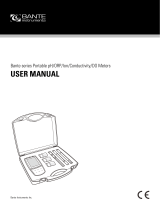
3.1.1 1-Channel Version
METTLER TOLEDO
M800
1
2
TB2
TB1
TB4
TB5
RECEIVER
EMITTER
TB3
5
6 6
3
4
7
Fig. 1: Overview 1-channel version
1 Housing, polycarbonate or stainless steel
2 VGA screen
3 Power supply terminals
4 Relay output terminals
5 Analog output / Digital input terminals
6 Sensor input terminals
7 Connection Turbidity sensor (InPro8000 Series)

Transmitter M800 16
© 05/2019 Mettler-Toledo GmbH, CH-8606 Greifensee, Switzerland Transmitter M800
Printed in Switzerland 52 121 825 D
3.1.2 2-Channel and 4-Channel Version
METTLER TOLEDO
M800
1
2
TB2
TB1
TB3 TB4 TB5
TB6
5
6 6
3
4
Fig. 2: Overview 1-channel version
1 Housing, polycarbonate or stainless steel
2 VGA screen
3 Power supply terminals
4 Relay output terminals
5 Analog output / Digital input terminals
6 Sensor input terminals

Transmitter M800 17
© 05/2019 Mettler-Toledo GmbH, CH-8606 Greifensee, Switzerland Transmitter M800
Printed in Switzerland 52 121 825 D
3.2 Display
3.2.1 Start Screen
After starting the M800, the following Start Screen (logout screen) is shown automatically. To re-
turn form the Menu Screen to the Start Screen press s. The M800 will return automatically after
240 seconds from the Menu Screen or any configuration screen to the Start Screen if the user
has not pressed the touch screen.
3.2.2 Activation Menu Screen
While the M800 shows the Start Screen (logout screen) touch the display to activate the Menu
Screen. To return to the Menu Screen from other menus press H.

Transmitter M800 18
© 05/2019 Mettler-Toledo GmbH, CH-8606 Greifensee, Switzerland Transmitter M800
Printed in Switzerland 52 121 825 D
3.3 Graphic Trend Measurement
Any single measurement may be displayed as a trend measurement over time. Measurement
values will be indicated by a value on the Y-axis and time elapsed on the X-axis of the graph
displayed. An actual measurement for the selected value will also be displayed numerically
above the graphic trend display. The measurement value is refreshed once per second.
Graphic trending will only display the data within maximum/minimum range. Out of range val-
ues or invalid values will not be displayed. The Y-axis will display the maximum value unit with
its range; X-axis unit uses “mins” for minutes for measurements less than one hour and “hrs” for
one day. 4 scales for X/Y-axis. The maximum value on Y-axis is one decimal place.
3.3.1 Activation Trend Display Screen
While the M800 displays the Menu Screen, touch any measurement value line of the display
screen twice (1-chan, 2-chan, 4-meas, 8-meas) to activate the trend display for that measure-
ment.
If a sensor is disconnected/connected a pop-up window come up; after closing the window, it
will go back to the Menu Screen.
Red/yellow bar on top line will display for any message occurring during trending. ‘H’, ‘P’,”AB”
will display when this channel is in hold or process.

Transmitter M800 19
© 05/2019 Mettler-Toledo GmbH, CH-8606 Greifensee, Switzerland Transmitter M800
Printed in Switzerland 52 121 825 D
3.3.2 Settings for Trend Display Screen
For setting configurations, touch any area of the graphic trend display to go to the pop-up win-
dow of this measurement parameter. Settings are at the default values. However, these settings
may be changed when options are available, as needed.
Time: Option button. For graphic display time (X-axis)
1-h (default value)
1-day
h
NOTE: 1 h means: 1 meas storage/15 seconds, totally 240 measurements for 1h. 1 day
means: 1 meas storage/6 minutes, totally 240 measurements for 1 day;
Range: Option button
Default(default value)
Individual
When “Default” modes are set for the maximum or minimum value, this indicates the full mea-
surement range for this unit. A Max or Min button is not displayed. If setting is selectable, the
user can set maximum and minimum settings manually.
Max: Edit button.
Maximum value of this unit on Y-axis. xxxxxx, floating decimal point.
Min: Edit button.
Minimum value of this unit on Y-axis. xxxxxx, floating decimal point.
Max Value > Min Value
h
NOTE: Settings for Y-and Y-axis and the corresponding measurement values are stored the trans-
mitters memory. A power down returns to default settings.
3.3.3 Deactivation Trend Display Screen
Press H in activated graphic trend screen to return to Menu Screen.
h
NOTE: If a sensor is disconnected/connected a pop-up window come up; after closing the win-
dow, it will go back to the Menu Screen.

Transmitter M800 20
© 05/2019 Mettler-Toledo GmbH, CH-8606 Greifensee, Switzerland Transmitter M800
Printed in Switzerland 52 121 825 D
3.4 Control / Navigation
3.4.1 Menu Structure
Below is the structure of the M800 menu tree:
Menu Screen
M800
Guided Setup
Measurement
Analog Outputs
Set Points
ISM Setup
General Alarm
ISM/Sensor Alarm
Display Setup
Digital Inputs
System
PID Controller
Service
Tech Service
User Management
Reset
RS485 Output
Clean
Channel Setup
Display Mode
Parameter Setting
Concentration
Curve Table
c
Calibration
Calibrate Sensor
Calibrate
Electronics
Calibrate Meter
Calibrate
Analog Outputs
Calibrate
Analog Inputs
Maintenance
Favorite 1…4
Set Wizard
S
Wizard
iMonitor
Messages
ISM Diagnostics
Calibration Data
Sensor Info
HW/SW Version
Log Book
C
Configuration
Temperature Source
/