Page is loading ...

MOBILE Toilet Installation
- 6 –
Anchoring the
Mobile
“S” Shaped
Bracket
‘L’ Shaped
Brackets
The mobile should be anchored if the unit will be installed in a vehicle that will move. There
are three anchoring brackets supplied with the unit which should be used to securely
anchor the toilet.
The ‘S’ shaped mounting bracket -
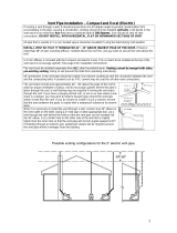
The ‘S’ shaped mounting bracket, (pictured below) is for attaching the top of the toilet to
the wall. (see diagram below)
1. Locate the ‘S’ Bracket (shown above), 2 nuts, 2 washers and
2 bolts.
2. Locate the two dimples (guides where to drill holes) that are just
left of centre, near the top of the unit.
3. Place the ‘S’ Bracket over the dimples to make sure the holes line
up. Using an electric drill with the drill bit(provided), drill a hole
through each of the 2 dimples on the top of the unit.
4. Place the ‘S’ bracket over the holes so that the top end of the
bracket is above the top of the unit (as shown in diagram left).
Once the bracket is in place, insert a bolt through each hole so that it is visible through the
vent hole in the top of the unit (see diagram below). Run a thin bead of silicone around the
stainless steel washer (provided) and place over the protruding bolt, on the inside of the
unit. Place a stainless steel nut over each protruding bolt and tighten.
Fastening the bracket to the wall:
1. Place the MOBILE against the wall where it will be mounted.
2. With a pencil, mark the location of the holes in the mounting
bracket.
3. Drill a small hole in each of the pencil markings to accept
anchoring screws. Use a #8 x 1” screw to anchor the
unit to the wall. Once installed, the vent pipe will hide the
bracket.
The ‘L’ bracket, (pictured left) is for attaching the toilet to the floor. (see diagram below)
1. Locate the ‘L’ Bracket in the desired location.
2. Remove the finishing drawer. Using the holes in the ‘L’ bracket as a guide, mark the
location of the two holes with a pencil. Use a drill with the drill bit (provided) to create
small holes in the side of the MOBILE tank being careful not to drill downward toward
the heating element.
3. Make sure the drilled holes line up with the holes in the
‘L’ bracket..
4. Place a small bead of silicone over the hole between
the ‘L’ bracket and the Mobile tank. Dip the bolt into
silicone and insert the bolt into the hole in the bracket
and through the corresponding hole in the Mobile tank.
5. Place a small amount of silicone into the centre of the
nut and fasten over the bolt to fasten the bracket.
Important: Ensure all bolts used for brackets are
sealed with silicone to prevent leakage.

- 7 –
Space
Required and
other
Installation
Considerations
Vent Pipe
Location
Installing the
Fan Filter Box
Leading the
Vent
Through the
Roof
The Deck or
Roof Vent
Drain
Installation
1. Compost is removed from the finishing drawer. Ensure that there is at least 15” in front of
the MOBILE Toilet so that the drawer may be removed from the unit.
2. Install the unit in a location where the safety drain can be connected. This drain exits from
the back of the unit and must slope downward at all points.
3. Install in a location where the vent pipe can be attached as per the instructions listed
on page #9.
4. Install in a location that is not air tight.
5. Ensure that there is a three-pronged plug with a GFI (ground fault interrupter) or 12 Volt
connection installed within 5 feet of the unit.
6. Ensure the MOBILE Toilet is protected from precipitation.
7. The toilet must be installed on a level surface or sloping slightly towards the back.
1. The vent stack should be installed as near to vertical as possible. Maximum of two 45°
bends. DO NOT RUN THE VENT HORIZONTALLY AT ANY POINT.
2. Insert the 3” vent inlet coupling into the 3” hole on the top of the unit.
3. Position the fan box in the vent stack where maintenance can be carried out
conveniently.
4. If using the flexible hose, use at the top of the filter box so that moisture does not collect
in the corrugations.
5. All connectors in the vent pipe should be sealed with silicone caulking.
6. Minimize the number of sharp angles as each reduces vent efficiency. Do not use
any 90 degree elbows, since this will reduce air flow substantially.
7. Where the piping is taken through the roof, a roof flashing should be used to seal the
installation.
1. Place the fan filter box in the vent stack where it is easily accessible to
replace filter materials.
2. Remove enough of the filter materials (carbon and zeolite) so that you will
only have about 1/2” (12mm) of carbon in one filter bag and 1/2” (12mm) of
zeolite in the other filter bag (too much filter materials will stop the air-flow in
the composting unit).
3. Place the zeolite and carbon filters on top of the plastic mesh inside of the
filter box. Place the top of the filter box into the bottom of the filter box (part
with plastic mesh).
4. When attaching the filter box to the vent, use the flexible vent hose to
connect to the vent from the top of the filter box and a rigid coupling at the
bottom of the filter box.
1. Locate the area on the roof where the vent will be installed.
2. Cut a 3” diameter hole through the roof where the toilet will be located.
3. Install the 3” vent through the roof and liberally apply the self-leveling roof sealant
around the edges of the vent. Completely seal all seams and areas where water can
penetrate. Let this cure before inspecting the vent and applying more sealant as
necessary.
4. Install deck or roof vent according to the manufacturer’s instructions.
DECK VENT NOT SUPPLIED: Purchase a deck vent which fits the decor and function of
your mobile vehicle. The deck fitting should discourage downdraft and also prevent liquid
(especially sea-water) from entering the toilet. It should also encourage ventilation of the
toilet at all times.
The safety drain must be connected as it will be required in all installations.
- Remove the orange cap from one side of the overflow drain assembly.
- Place a 1” hose clamp over the end of the drain hose that will be connected to the
overflow drain assembly.
- Push the drain hose over the ribbed end of the over-flow drain and clamp with the 1” SS
hose clamp.
- Connect the 1” hose to an approved drainage facility.
- The safety drain is gravity fed. The drain hose must be below the level of the safety drain
in order to function.
/
