Page is loading ...

CTO-00002
SM AC/DC Kit
Jan 2011
Rev.D1
Product Info: (905) 332-1314 Fax: (905) 332-1315 Tech. Service: (888) 341-0782 Ext 218
E-mail: compost@sun-mar.com http://www.sun-mar.com
600 Main St. 5370 South Service Rd.
Tonawanda, N.Y. Burlington, ON
14150-0888 U.S.A. L7L 5L1 CANADA
AC/DC Kit
CONVERSION AND INSTALLATION
INSTRUCTIONS
Kit required for conversion of electric units to also operate in
non- electric or 12 Volt mode. For use with Excel and all Centrex
Systems.
Tools Required

The AC/DC kit is required to convert an electric Excel or Centrex System for use without electricity or
where 12 volt DC electricity is only available. Non-electric units have certain features which the electric
units do not have. The non-electric units have a 4" vent stack and a 1" diameter drain assembly. The
installation of a 4" vent stack is required. The drain is required on the non-electric units since evapora-
tion is not assisted by the heating element, there will be overflow liquid.
PARTS IN THE KIT
5 X 4”X 31.5” Vent Pipe 4 X 4” ABS Coupling
1 X Clear Scoop 1 X 4.25” Hole Saw
1 X 6” Diffusor 1 X Microbe Mix 50g.
1 X 12 Volt 2.4 Watt Fan 1 X Compost Quick 250ml.
1 X 4” Inlet Pipe 1 X 1” SS Hose Clamp
1 X 1”X 8’4” Drain Pipe
**You may also require a marker pen, a phillips screwdriver, an exacto knife, masking tape, a drill and a
1/8” drill bit
CREATING THE HOLE FOR THE VENT
1. UNPLUG YOUR COMPOSTING UNIT and disconnect the 2” vent stack. If the vent connection is
sealed with silicone, use exacto knife to break the seal between the vent stack and the unit.
2. Locate the composting unit in an area where you have access to the top of the unit.
3. Removing the fan from the unit. The area where you will need to create the hole for the 4” vent is
directly above the fan assembly.
To remove the fan, locate the 8 snap caps around the large plate near where the 2” vent stack
connects to the unit. Using your exacto knife, pry the 8 snap caps off, exposing the screw heads.
Remove the all 8 screws and set all parts aside for reuse. Lift the fan out of the unit and set aside.
CONVERTING YOUR COMPOSTING UNIT
1) All vent should be vertically installed. Limit bends in the vent stack to no more than
2 - 45 ° bends.
2) If you will be installing venting on a steeply pitched roof where snow shear may
occur; Install a heavier pipe through the roof and feed the enclosed vent through
the heavier pipe. Seal between the pipes with expandable foam or other such
water-tight substance. The heavier pipe should be able to withstand the weight of
sliding snow.
3) If there is more than 36” of vent needed above the roof line to reach 24-30”
above the highest peak of the roof(diffusor included in measurement), use guide
wires to secure the vent above the roof.
4) The vent must be installed separately from ALL other household vents. Venting
cannot be merged with other venting. Doing so will prevent the unit from
operating odorlessly.
5) All connectors in the vent pipe should be sealed.
6) The diffusor should be glued vertically on to the top of the vent pipe. This
assembly helps draw air up the vent pipe.
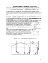
LEADING THE VENT THROUGH THE ROOF
As shown in the installation, the vent stack should end about
30” above the peak of the roof so that it is less subject to downdraft. Where the pipe
is taken through the roof, a roof flashing may be required to seal the installation. If you
are in an area where snow shear is a danger, you may wish to install a heavier pipe
around the vent pipe where it exits from the roof. If you do choose to do this, ensure
that you seal the area between the pipes with a waterproof substance to prevent leaks.
INSTALLING THE OVERFLOW DRAIN
When used without electricity, evaporation is completely dependant upon the climate where the unit is installed. For this rea-
son, the overflow drain should be connected as it will be required.
-Remove the orange cap from the drain assembly.
-Place a 1” SS hose clamp over the end of the drain hose that will be connected to the overflow drain assembly.
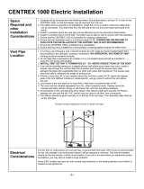
VENT PIPE LOCATION
- 1 -- 4 -

4. Locating the center for the hole.
Use the picture to locate the location for the hole for the 4” vent on your composting unit.
Once you have located the center, make a mark for the pilot hole.
5. Once you have marked the hole for the pilot, use a 1/8" drill bit to drill a small pilot hole on the mark.
6. Before you drill the 4" hole, place the 4.25" hole saw on the unit (as shown
above) with the pilot bit in the pilot hole you have drilled. Ensure that the allignment is exact before you drill.
Ensure that the hole is centered in the correct area (as shown in the the pictures above). Once you are
satisfied that the hole is in the proper location, proceed to step 7.
7. Using the hole saw. Make sure to press down with even pressure on the hole saw so that the blades bite
evenly into the top of the unit. Carefully apply firm pressure until the hole is cut in the unit.
8. : Use masking tape to secure the handle under the seat. This will ensure that the handle will
not end up at an odd angle when the fan is replaced. Once the handle is secure, ensure that the opening in
the drum is centered under the opening in the bowl liner. Slide the stainless steel shaft into the cone on
the bottom right corner of the fan plate. Once you have completed this step, you may proceed with replacing
the fan.
9. Replacing the fan:
Replace the fan plate over the hole in the unit from where it was removed. Line up the screw holes.
Insert the screws into the holes, making sure each screw has a CKS washer around the screw. Fasten
all 8 screws. Ensure that the screws are not to over-tightened. Replace the snap caps.
Excel
Centrex 1000
Centrex 2000
INSTALLING THE VENT
Place the vent inlet coupling into the hole that you have created for
the 4” vent so that the 1” of smaller diameter pipe is protruding into
the hole in the top of the unit. This is the first piece of the venting.
Once you have finished assembling the vent, you should run a bead of
silicone around the inlet coupling to prevent odor from escaping.
-The 12 volt fan should be used if there will be any bends in the
vent pipe configuration, if you have a Centrex 3000, if the toilet
will be used as an AF waterless toilet or if you are in an area
where you will experience regular downdraft.
-The 12 volt fan may not be necessary if the vent is installed
vertically as per specifications outlined under “Vent Pipe Location”.
- If you do choose to install the 12 volt fan (included with kit), it
must run continually for the duration of the time that you will
spend at your house or camp.
- If the 12 volt fan is not running, it will cause a blockage in the
vent pipe and will reduce the venting capacity of the 4” vent.
INSTALLING THE 12 VOLT FAN
Install the 12 volt fan on the inlet coupling with the large side with the wires protruding facing
upwards (as shown in the picture at right).
The 12 Volt Fan may be powered with a battery that is connected to a
generator, solar panel, or other alternative energy system. For use in AC,
purchase a 12 Volt to AC Adapter and snip off the female end. Wire the
positive wire to the red wire on the fan, and the negative wire to the blue wire on the fan. Tie
them off with wire connectors, and plug your AC Adapter into the wall.
Use silicone caulking to seal the conections between the inlet coupling where the bottom con-
tacts the composting unit and all connections on the vent. Do not glue the fan to the vent
stack.
INLET COUPLING
12 VOLT FAN
Centrex 3000
- 2 - - 3 -
/