
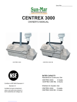
CENTREX 3000 Electric Installation
- 6 –
Space
Required and
other
Installation
Considerations
Vent Pipe
Location
Electrical
Considerations
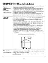
1) To facilitate maintenance and compost removal, ensure that there is at least 17” in front of the
CENTREX 3000, for removal of the drawer and access panel.
2) The safety drain is required in ALL installations. Install the unit in a location where the safety drain
can be connected. This drain exits from the left side of the unit and must slope downward at all
points.
3) Install in a location where the vent pipe can be attached as per the instructions listed below.
4) Install in a location that is not air tight. The toilet must be able to vent to ensure odor free operation.
5) Ensure that the CENTREX 3000 is accessible for ongoing maintenance.
6) Ensure that the installation area is a minimum height of 28”. WE DO NOT RECOMMEND DIGGING
BELOW GROUND TO FACILITATE THE INSTALLATION OF THE CENTREX 3000.
7) Ensure the CENTREX 3000 is protected from precipitation.
8) Ensure that the unit is installed on a level surface or sloping slightly towards the safety drain.
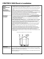
1) If running a vent through a wall, it should be done at a 45° angle to prevent condensation from
accumulating in the vent pipe, causing a constriction. NO HORIZONTAL SECTIONS OF VENT.
Venting should be installed vertically.
2) All vent pipe that is exposed to the outside or in a non-heated space should be insulated if
using the unit during cold weather.
3) INSTALL VENT SO THAT IT TERMINATES 24” - 30” ABOVE HIGHEST PEAK OF THE ROOF.
4) If you will be installing venting on a steeply pitched roof where snow shear may occur; Install a
heavier pipe through the roof and feed the enclosed vent through the heavier pipe. Seal
between the pipes with expandable foam or other such water-tight substance. The heavier pipe
should be able to withstand the weight of sliding snow.
5) If there is more than 36” of vent needed above the roof line to reach 24-30” above the highest
peak of the roof (diffusor included in measurement), use guy wires to secure the vent above
the roof.
6) Limit bends in the vent stack to no more than 4 that have a combined total of 180 °.
7) The vent must be installed separately from ALL other household vents. Venting cannot be
merged with other venting. Doing so will prevent the unit from operating in an odorless fashion.
8) All connectors in the vent pipe should be sealed. Use silicone caulking to seal the connection
between the vent and the fan. PVC cement may be used on all other vent connections.
9) The diffusor should be glued vertically on to the top of the vent pipe. This assembly helps draw air
up the vent pipe.
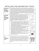
Possible venting configurations for the 2” electric vent pipe.
The fan will run continuously 24 hours per day. A ground fault interrupter (GFI) circuit is recommended
for any unit installed in an environment where it will be exposed to moisture. This may be installed
directly on the wall socket or at the circuit breaker. If you are in an area where you experience power
fluctuations, you may wish to install a surge protector.
Some 230V models may have an over current fuse protection on the heating element circuit which is
located on the electric box.

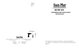
CENTREX 3000 NE (Non-Electric) Installation
- 7 –
Space
Required and
other
Installation
Considerations
Vent Pipe
Location
Vent Inlet
Coupling
12 Volt Fan
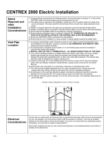
1) To facilitate maintenance and compost removal, ensure that there is at least 17” in front of the
CENTREX 3000, for removal of the drawer and access panel.
2) The safety drain is necessary for ALL installations. Install the unit in a location where the
safety drain can be connected. This drain exits from the left side of the unit and must slope
downward at all points.
3) Install in a location where the vent pipe can be attached as per the instructions listed below.
4) Install in a location that is not air tight. The toilet must be able to vent to ensure odor free
operation.
5) Ensure that the CENTREX 3000 NE is accessible for ongoing maintenance.
6) Ensure that the installation area is a minimum of 28” in height. WE DO NOT RECOMMEND
DIGGING BELOW GROUND TO FACILITATE THE INSTALLATION OF THE CENTREX
3000.
7) Bends in the vent, installation near hills or over hanging trees may cause down draft. A 12 volt
fan may be necessary.
8) Competing appliances (ie. wood stove) may require an air intake installed from the outdoors if
the unit is installed in an enclosed basement. A 12 volt fan may be required.
9) Ensure that the unit is installed on a level surface or sloping slightly towards the safety drain.
1) All vent should be vertically installed.
2) Limit bends in the vent stack to no more than 2 - 45 ° bends.
NO HORIZONTAL SECTIONS OF VENT.
3) INSTALL VENT SO THAT IT TERMINATES 24” - 30”
ABOVE HIGHEST PEAK OF THE ROOF. If the vent is being
installed on a steeply pitched roof where snow shear may
occur; Install a heavier pipe through the roof and feed the
enclosed vent through the heavier pipe. Seal between the
pipes with expanding foam or other such water-tight material.
The heavier pipe should be able to withstand the weight of
sliding snow.
4) If there is more than 36” of vent needed above the roof line
to reach 24-30” above the highest peak of the roof (diffusor
included in measurement), use guy wires to secure the vent
above the roof.
5) The vent must be installed separately from ALL other
household vents. Venting cannot be merged with other
venting. Doing so will prevent the unit from operating
odorlessly.
6) All connectors in the vent pipe should be sealed. Use
silicone caulking to seal the connections.
7) The diffusor should be glued vertically on to the top of the
vent pipe. This assembly helps draw air up the vent pipe.
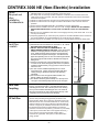
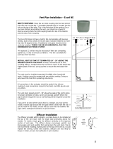
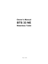
Place the vent inlet coupling into the hole on the top of the unit
for the 4” vent and so that the 1” of smaller diameter pipe is
protruding into the hole. This is the first piece of the venting.
Once you have finished assembling the vent, run a bead of
silicone around where the inlet coupling meets the top of the
composting unit to prevent odor from escaping.
Install the 12 volt fan on the inlet coupling with the large side
with the wires protruding facing upwards (as shown in the
picture at right). When the 12 volt fan is turned off, it forms an
obstruction in the vent, and should therefore run continuously
while the cottage or home is occupied. An optional switch (as
small as 1 amp) may be installed, and the fan turned off when
the toilet will not be used for several weeks. The red wire
should be connected to the positive (+) terminal on your battery
or DC system, and the blue wire to the negative terminal (-).
The 12 volt fan may be powered with a battery that is
connected to a generator, solar panel, or other alternative
energy system.

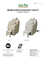
Installation Common To Electric and NE Units
-
- 8 -
Leading the
vent through the
roof
Leading the
vent through the
wall
The Diffusor
Drain
Installation
Handling
Effluent
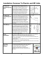
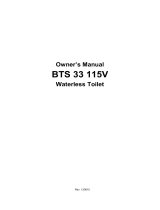
The vent stack (shown in diagram) should end
approximately 30” above the peak of the roof so that
it is less subject to downdraft. Where the pipe is
taken through the roof, a roof flashing may be
required to seal the installation. If you are in an area
where snow shear is a danger, you may wish to
install a heavier pipe around the vent pipe where it
exits from the roof. If you do choose to do this,
ensure that you seal the area between the pipes
with a waterproof substance to prevent leaks.
When it is necessary to lead the vent through a wall,
connect one 45° elbow on the vent outlet on the unit.
Using a hole saw or other appropriate tool, cut a
hole through the wall board behind the unit so that
the vent pipe can be inserted into the 45° elbow. Cut
a similar hole on the other side of the wall that is
slightly higher than the inner hole so that the vent
pipe will be angled upward at 45°. If installing
through an exterior wall, waterproof sealant will be
required around the vent pipe where it emerges from
the building.
The diffusor provided with the unit is a simple device
to be installed at the top of the vent stack with the
larger pipe protruding above the smaller. To install,
simply glue the diffusor vertically on the topmost
section of vent pipe. The diffusor design encourages
updraft, and discourages wind and weather from
going down the vent stack. We do not recommend
installing anything else on the top of the vent as it
could impede the venting. Unlike wind
turbines,
diffusors are less likely to freeze in winter, and are
more effective in calm weather.
The safety drain
MUST
be connected as it will be required in all Centrex 3000 NE
installations or Centrex 3000 electric with ultra-low flush toilets.
- Remove the orange cap from one side of the overflow drain assembly.
- Place a 1” hose clamp over the end of the drain hose that will be connected to the
overflow drain assembly.
- Push the drain hose over the ribbed end of the over-flow drain and clamp with the 1”
SS hose clamp.
- Connect the 1” hose to an approved drainage facility.
- The safety drain is gravity fed. The drain hose must be below the level of the safety
drain in order to function.
The following are possible options to take care of the liquid :
- Feed into a lined pit filled with gravel and sand. Such a
recycling bed also ensures a closed loop system.
- Feed into a small cesspit or “French drain”.
- Plumb into an existing septic or holding tank line.
Installation should be in accordance with applicable local
regulations.

– 9 –
Positioning The
Collection
Chamber
Installing the
waste pipe
Installing the
Ultra Low
Flush Toilet
Line the bottom of the collection chamber with the plastic bag (provided). Place the
collection chamber base on the right side of the CENTREX 3000 so that the base
rests under the opening in the patented bio-drum. Place the top of the collection
chamber on the base. SUN-MAR Autoflow® technology allows compost to
automatically deposit into the collection chamber.
When installing the waste pipe from the toilet to the unit, the following should be
considered:-
1) The pipe should be either 45 ° or vertical (if composting unit is directly below
toilet), or at a 2-3 ° angle (1/8”-1/4” or 3-13mm drop per foot maximum) so that
the waste travels with the liquid.
2) Pipe should not slope upwards at any point.
3) Connections should be snug so that waste does not cause blockage.
4) It is recommended that the waste pipe be no longer than 15 feet (460cm)
without installing a clear out port(a Y fitting with screw on end cap) near the
toilet to provide easy access should it be required.
5) Use a soft sealant, such as silicone for the connection of the waste pipe to the
unit so that the unit can be moved for servicing or other reasons should this
ever be required.
6) Insulate pipe if unit is to be used during the winter.
7) For longer installations of waste pipe, ensure the waste pipe is supported
to prevent sagging.
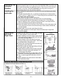
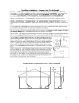
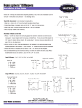
1) Make sure the center of the floor flange is at least
11 inches (280mm) from the back wall.
2) When Installing a new floor flange, ensure that the
toilet mounting bolts align properly with ultra low
flush toilet mounting pattern.
3) Secure flange to floor using flat head screws
through counter-sunk holes in flange. Insert bolts
into slotted holes in flange(Fig. A)
4) Position floor seal by pressing the floor bolts up
through the holes in the seal.
5) Set toilet in place with bolts protruding up through
mounting holes in base (Fig C).
6) Install washers and hex nuts provided with toilet.
Tighten nuts down equally with standard 7/16”
(12mm) open end wrench.
7) Connect water supply line to water valve (1/2” or
13mm MPT) inlet using appropriate fittings (Fig D)
8) Turn on water supply and flush toilet to test for
leaks.
9) Attach pedestal and pedal covers to toilet base.
See instructions below.
-
 1
1
-
 2
2
-
 3
3
-
 4
4


Sun-Mar CENTREX 3000 NE Installation guide
- Type
- Installation guide
- This manual is also suitable for
Ask a question and I''ll find the answer in the document
Finding information in a document is now easier with AI
Related papers
-
 Sun-Mar CENTREX 1000 NE Installation guide
-
 Sun-Mar CENTREX 2000 NE Installation guide
-
 Sun-Mar EXCEL NE (White) Installation guide
-
 Sun-Mar EXCEL (white) Installation guide
-
 Sun-Mar CENTREX 3000 series Owner's manual
-
 Sun-Mar AC/DC Kit Operating instructions
-
Sun-Mar Excel NE CSEM-01400WBB Owner's manual
-
 Sun-Mar SPACESAVER Owner's manual
-
 Sun-Mar A/F Waterless Kit Operating instructions
-
 Sun-Mar CCAF-00003 Installation guide


Other documents
-
Unbranded 12 V FAN (2.4 WATT) Operating instructions
-
Nexus SFM-1000 Datasheet
-
Sharper Image Mariner's Stormglass Owner's manual
-
 BTS BTS33NE User guide
-
 BTS BTS33115V User guide
-
Mantis 4000 Owner's manual
-
 Auralex Hemisphere™ User guide
-
 GSI Outdoors AUTOFLOW 2TFC User manual
-
Telair Dualclima 8400H 60Hz User manual
-
 Centricity Home Owner's manual


