Page is loading ...

DIGITAL ACTIVE INFRARED SENSOR
38mm
~
50mm
INSTRUCTION MANUAL
SUGGESTIONS FOR INSTALLATION 1
2
1
PARTS DESCRIPTION
SUGGESTIONS FOR INSTALLATION 2
3
4
INSTALLATION
W ALL MOUNT
Each bracket to be reversely attached.
1. Pull the wire through the
wire hole of the pole.
2. Attach the bracket to the pole with the pole holder.
POLE MOUNT
Pole mount back-to-back
Ensure the sensors line of sight is
free from any false alarm sources
such as bushes, trees, etc. ( Pay
attention to these as they may
change seasonally.)
Ensure strong sunlight or car
recommended.)
headlights do not shine directly
from the optical axis is not
on to the receiver. (Within 2
Direction of installation
Horizontally 180
Vertically 20
Because angle of reflection mirror is adjustable
unit can be installed in various directions.
in 90 horizontally and 10 vertically, the
In case of jump phenomenon, as shown
of transmitter and receiver to the following
section in the above, change the disposition
manner shown s ection.
COVER
MAIN BODY
Connection
Terminal
LED
Wire Hole
Monitor Jack
(Only for Receiver)
Obscuration Time
Adjustment
(Only for Receiver)
4Frequency Channel
Switch
Tamper
Horizontal Angle
Adjustment Dial
Viewfinder
Cover Lock
Screw
LENS
Vertical
Adjustment
Screw
LED
GOOD ( Green ) POWER ( Green )
:on when optically aligned : on when the transmitter is working
:off when optically not aligned
LEVEL ( Red )
:on when Alarm is activated in accordance with Alarm LED ( Red )
ALARM ( Red )
:on when Alarm is activated in accordance with LEVEL ( Red )
RECEIVER TRANSMITTER
Monitor jack : Should be used for making the optimum optical axis adjustment
( Refer to ' how to use the monitor jack' )
Obscuration time adjustment : To be used for setting the obscuration time
( Refer to ' adjustment of obscuration time ' )
Ensure the sensors are
mounted on a stable and
firm fixing.
Note that here the protection
distances refers to the sheet
below.
Height of installation and
protection distance
Receiver
Transmitter
ReceiverTransmitter
Receiver
Transmitter Transmitter
Receiver
Bracket
Pole holder
Pole cover
1. Loosen screw holding cover and
remove the cover.
2. Attach the mounting pattern paper
to the wall, mark the installation
holes, and make guide holes.
3. Break knock-out and pull wire
through.
5. Connect wires to the terminal.
( Refer to the Terminal Configuration
right hand side )
6. Make the optimum optical adjustment as per
section 5 and confirm system operation before
replacing covers.
Wiring distance
POWER ALARM
TAMPER
RECEIVER
TA MPER
TRANSMITTER
POWER FREE
TERMINAL CONFIGURATION
4. Pull wire through, install SBM
onto flange and the wall.
knock-out
Protection Distance
Spread of Beam
0.7
~
1.0m
14mm
33mm
33mm
GOOD
LEVEL ALARM
POWER
1 2 3 4 5 6 7
1 2 3 4 5 6 7
SBT-100F
SBT-150F
SBT-80F
SBT-60F
SBT-30F
SBT-40F
SBT-30F
SBT-100F
SBT-80F
SBT-150F
30m
80m
100m
150m
4.5m
3.0m
2.4m
0.9m
SBT-60F
60m
1.8m
SBT-40F
40m
1.2m
Spread of
Beam
Protection
Distance
Model
Model
Voltage
Wire
diameter
SBT-30F
SBT-40F SBT-60F SBT-80/100F
24V 12V 24V 12V 24V 12V 24V
2
¦Õ
2
¦Õ
2
¦Õ
2
¦Õ
12V
0.3mm ( 0.6)
0.5mm ( 0.8)
0.75mm ( 1.0)
1.25mm ( 1.2)
12V 24V
SBT-150F
2143m
3750m
5000m
7500m
238m
833m
556m
417m
2143m
3750m
5000m
7500m
238m
833m
556m
417m
2143m
3750m
5000m
7500m
238m
833m
556m
417m
2143m
3750m
5000m
7500m
238m
833m
556m
417m
2143m
3750m
5000m
7500m
238m
833m
556m
417m

2. Look through the
v iewfinder as shown
b elow.
Vertical adjustment
to raise
(loosen)
to lower
(tighten)
1
5
4
3
2
ADJUSTMENT OF OBSCURATION
Obscuration time control
CONFIRMATION OF OPERATION
After completion of the installation, confirm correct operation by suitable walk test. Refer to the following LED
indications during the walk test. Confirm tamper operation prior to replacing covers. Confirm system operation
with covers replaced.
NOTE: Conduct a Walk Test at least once a year
OUTLINE DIMENSION
9
TROUBLE SHOOTING GUIDE SPECIFICATION
Caution: Obscuration time settings exceeding 70msec (exceeding a setting of 1) do
Set the obscuration time of the receiver by adjusting the obscuration time control
conditions where there are a lot of birds or wind blown material.
5
ADJUSTMENT OF OPTICAL AXIS
The best adjustment of optical axis can be done by reading the output voltage of the
monitor jack.
7
10
6
8
It is important to ensure correct optical alignment between the
transmitter and receiver for proper operation.
HOW TO USE THE MONITOR JACK
Scale 1
fast running at full
Scale 2 Scale 3 Scale 4
walking with quick normal walking
slow action
speed(8.6m/s) steps(1.2m/s) (0.6m/s)
(0.2 0.4m/s)
to the required setting according to the sketch beside. The obscuration time should
be set lower to detect faster moving targets, however care should be taken to note
the environmental conditions as the obscuration time should be set higher to ignore
not comply with the requirements in UL639, Instrusion Detection Units.
Possible cause
A Remedy
Indication lamp of Transmitter
does not light.
Improper voltage of power supply Check power supply and wiring
Power supply indication Lamp
of Receiver does not light.
Improper voltage of power supply Check power supply and wiring
Alarm indication lamp does not
light even when the beams are
intercepted.
Remove the reflecting object or
Check two beams to intercept
at the same time.
Adjust obscuration time setting
to be shorter.
Although alarm LED lights
Melted bridge on the signal
Check the wiring.
It needs to be repaired.
Alarm LED on the Receiver
does not turn off.
Inadequate optical axis.
Shading objects between the
of the Transmitter and/or Receiver.
Readjust the optical axis.
Remove the shading objects.
Clean optics with soft cloth.
Bad wiring connection.
Change of supply voltage.
Shading objects moving by wind
Unstable installation of the sensor
unit.
Incomplete optical axis adjustment.
Birds and other large flying objects
intercept the beam.
Check the wiring connection.
Check the voltage (for stabilized
supply voltage.)
Remove the shading objects or
Fix steadily.
Readjust the optical axis.
Readjust the obscuration time
to be longer or reposition.
Infrared beam from Transmitter is
sent into the Receiver.
Shorter obscuration time than that
Q Symptom
Intermittent alarm.
intercepted, alarm does
when the beams are
not ring.
reflected on another object and
Two beams are not intercepted
set on the obscuration control.
at the same time.
Broken wires or short on the
(Wrong current on the signal wires)
connection
signal wires.
Transmitter and the Receiver.
Dirty cover or dirty reflection mirror
between the Transitter and the
Receiver.
change the place for installation
and the optical axis direction.
change the place for installation.
Protection range (outdoor)
Distance allowance
Infrared beam
Detection system
Light source
Interruption Period
Power Input
Power consumption
Operation Temperature
Tamper output
Optical axis horizontal adjust
Optical axis vertical adjust
Collimator
Measure for moisture/frost
functions
Weight
2-Beam
2-beam simultaneous cut-off detection
Infrared LED
Relay contact, form 'C' contact rating
AC/DC 24V, 0.5A Max.
Normally closed voltage free contacts 50m A.
Finder ( peep window )
Slit type cover,heater option
Monitor jack output,OK monitoring,AGC circuit,
Adjustable beam interruption time
800g(28.2oz) (Transmitter and Receiver)
Dimenstion(H W D)
SBT-30F
350m
(1,148ft)
50~700 msec (Selectable)
DC 10.5V~28V
65mA
Model
Alarm output
80-100m
(262-328ft)
1,100m
(3,608ft)
650m
(2,132ft)
40-60m
(131-196ft)
5-30m
(16-98ft)
70mA
75mA
20
10
180
90
450m
(1,476ft)
30-40m
(98-131ft)
70mA
SBT-40F SBT-60F SBT-100F
-25 C~+55 C(-13 F~+131 F)
196.5 82 73.5mm (7.7" 3.2" 2.9")
Good Sensitivity
Alarm Activated
Power LED (green) is on
Good LED (green) is on
Alarm (red) .Level (red) LED are on
Poor Sensitivity
Level LED (green) is on
Operating
Conditions
Indication
Transmitter
Transmitting
Receiver
1. Insert the meter pins into the monitor jack.
( pay attention to the polarity because of DC voltage )
2. a) Adjust the horizontal adjustment until the output is at a maximum.
b) Adjust the vertical adjustment screw to obtain best signal.
( Do not interrupt beam by hands during the adjustment )
3. The following minimum voltages should be obtained to ensure best
performance.0.85V for all of the SBT-XXF series.
If this is not obtained then the transmitter and receiver should be
re-aligned.
Monitor Jack
1. Turn on the power supply after uninstallation.
Place the viewfinder on either right or left hand
side of the lens whichever makes easier viewing.
viewfinder
Transmitter
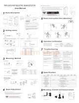
Channel Switch
Receiver
2Long distance
stack up
protection
1Long distance
protection
3perimeter protection
3. Adjust the angle of the lens via the
Horizontal angle adjustment and the
Vertical adjustment screw so that the
sensor can be seen in the center of
the Viewfinder.This adjustment is carried
out on both the Transmitter and Receiver.
Confirm after adjustment that the green
GOOD LED is on, otherwise alignment
should be readjusted.
NOTE: After completion of optical adjustment,
ensure that both filters on the receiver
are replaced to their original position
behind the mirrors.
To avoid the mutual interference ofbeams,please set the beams at different channels,
when installing more than one pairs at the same time.
TR:Transmitter; RE:Receiver
Examples of the installation as below.
73.5
67.0
196.5
82.0
38~50mm
1
0cm
CH1 CH4CH2 CH3
CH1 CH4CH2 CH3
900m
(2,952ft)
60-80m
(196-262ft)
75mA
SBT-80F
100-150m
(328-492ft)
1,600m
(5,249ft)
SBT-150F
80mA
SHENZHEN SUNWAVE ELECTRONICS CO., LTD.
http://www.sunwave.cc
CHINA
TEL: +86-755-8998-3101 FAX: +86-755-8998-3102
No.21 Plant, Da Wei Industrial Zone, Huang Ge Keng,
Heng Gang Town, Shenzhen
P/N W.97.0058 Rev.: A
/