Page is loading ...

Multi Photoelectric Beam Detector
Installation Instructions
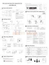
3. Installation
①Fix the base unit with screw bolts
on the wall.
1. Precautions on Installation
Thank you for purchasing SASO Multi Photoelectric Beam Detector. SASO MPB-30D4 will provide reliable service for a long term
when properly installed. Please read the following instructions very carefully for accurate and effective use.
Note: SASO MPB-30D4 is designed to detect an intruder and to sound an alarm when detected; it is not to prevent burglary.
We are not responsible for damage or losses from accident, theft, natural calamity, misuse, abnormal use, improper installation
and bad maintenance.
Do not install the unit where
exposed to direct sunlight. Do not install in a place where
it cannot be fixed stably. Do not install in places where
obstructions are laid within
detection range.
Do not install in places where
dirt can be put on the unit.
MPB-30D4
2. Parts Description
②Connect wires to the terminal.
(Refer to 7. WIRING)
③After angle adjustment,
fix the masking seat to the body
unit by tightening screw bolts.
(Refer to 6. Angle Adjustment)
- Receiver - Transmitter
Cover
Base Unit
Lens cover
Body
Unit
Fixing bracket
Transmitter (TX)
Receiver (RX)
④Put on the cover.

①Connect to electrical power source.
②Align the lens of transmitter and receiver.
③Check LED on receiver and then check lighting / blinking / blackout for each beam.
4. Response Time Adjustment (Auto)
5. Application
6. Angle Adjustment
Status Condition
Good Corresponding Blue LED Off
Readjust Corresponding Blue LED Blinks
Alarm Red & blue LED On
* Green LED lighting when transmitter is turned on/ Green LED blackout when transmitter is turned off.
2 Beams blocked : 300m/sec 3 Beams blocked : 100m/sec 4 Beams blocked : 100m/sec
Beam No.2 LED(blue)
Beam No.1
LED(blue)
Beam No.3
LED(blue)
Beam No.4 LED(blue)
※Window ※Front Door and Outside ※Balcony
※Examples of Installation in Different Positions
※MPB Series has automatic response time adjustment according to the number of beams.
- Receiver
ALRAM
LED(red)
- Transmitter
Power LED (Green)
Status Condition
Power On Green LED On

7. Wiring
8. Troubleshooting
Problem
Inactive Green LED
Inactive LED when beam
is blocked
Blue LED is keep lighting
Periodic False Alarm
Possible Cause
- Electrical power is cut off.
- Inferior wire or wire disconnected.
- Electrical power is cut off.
- Inferior wire or wire disconnected.
- Beam of transmitter is reflected on other
objects and goes into the receiver.
- Improper beam adjustment
- There is an object between TX and RX.
- Lens is covered with substance or stain.
- Wiring is improper.
- Electric pressure is improperly supplied.
- There is an object between TX and RX .
-Installed in places near noisy machineries.
- Installed in places where fixation is not stable.
- Lens is covered with substance or stain.
- Improper beam adjustments
Possible Solution
- Supply electrical power.
- Check wiring.
- Supply electrical power.
- Check wiring.
- Remove the object or change the direction
of beam.
- Readjust the angle.
- Remove the object between TX and RX.
- Remove substance or stain with soft cloth.
- Check wiring.
-Supply stable electric pressure.
- Remove the object between TX and RX.
- Change location for installation.
- Install at stable positions.
- Remove substance or stain with soft cloth.
- Readjust the angle.
- Examples of Wiring
Example 1 Example 2 Example 3
- Available Wiring Distance (Based on 1 Set and DC12V)
Voltage
Wiring size
Note:
1) Maximum wiring distance when two or
more sets are connected is the value
above divided by the numbers of sets.
2) The signal line can be wired to
distance of up to 1,000m with AWG22
telephone line..
4 beams
AWG 22(Dia 0.65mm) 260m
AWG 20(Dia 0.8mm) 400m
AWG 18(Dia 1.0mm) 630m
AWG 16(Dia 1.1mm) 900m
T R R T
(12VDC)
Control Panel
}
}
}
1 2 1 2 5 6 1 2 5 6 1 2
Alarm(1ch)
Power
Alarm(2ch)
T R R T
Control Panel
(12VDC)
}
}
1 2 1 2 5 6 1 2 5 6 1 2
Alarm Signal
Power
T R
1 2 5 6
1 2
(12VDC)
Control Panel
}
}Alarm Signal
Power
NO Color Polarity NO Color Polarity
1 Red + 5 Blue COM
2 Black - 6 Yellow N.C
3 White + 7 Brown N.O
4 Green - 8 Orange(Gray) N.O
- Receiver - Transmitter
NO Color Polarity
1 Red +
2 Black -
3 White +
4 Green -

9. Specifications
* Caution: Above specification is subject to change without prior notice for improvement.
10. External Dimensions
832
35
34
Model MPB-30D4
Detection Range Indoor, Outdoor : 15m
Number of Beams 4
Supply Voltage DC 10 ~ 25V (Polarity)
Current 120mA
LED
Signals
TX Power ON: Green LED ON
RX Angle Good: Green LED OFF, Readjustment : Green LED Blink, Alarm : Green/Red LED ON
Response Time 100ms / 300ms
Alarm Output Dry contact relay output 1C, Contact action: 2+0.5 sec,
Contact capacity: 30V(AC/DC) 1A or less
Temperature -20℃~ +60℃
Beam Adjustment 190°(±95°) right/left
Mounting Site Outdoor, indoor wall or window frame (Town house, apartment complex, luxury villa etc.)
Weight (g) TX : 478g
RX : 488g
Dimensions (mm) H832 x W34 x D35
Materials Aluminum, PC resin, ASA resin
Unit: mm
/