Page is loading ...

Strain Guage Indicator: 409-W
REF NO: m59A/om/501
Issue NO: 03
Page 1 of 34
User’s Manual
409-W
Strain Gauge Indicator
Masibus Automation and Instrumentation Pvt. Ltd.
B/30, GIDC Electronics Estate,
Sector-25, Gandhinagar-382044, Gujarat, India
Phone : +91-79-23287275/79.
Fax : +91-79-23287281.
Email: [email protected]
Web: www.masibus.com

Strain Guage Indicator: 409-W
REF NO: m59A/om/501
Issue NO: 03
Page 2 of 34
Contents
1. Introduction ............................................................................................................. 4
1.1 Product Overview/Description .......................................................................................................................... 4
1.2 Model and Suffix code ....................................................................................................................................... 4
1.3 Accessory ........................................................................................................................................................... 4
2. Safety/Warning Precaution ..................................................................................... 4
3. Front Panel Description .......................................................................................... 5
3.1 Keyboard and Operation ................................................................................................................................... 5
4. Panel Cutout Dimension ......................................................................................... 6
5. Sticker details .......................................................................................................... 7
5.1 Terminal Arrangement Diagram ....................................................................................................................... 7
5.2 Connection diagram for SGI Input ..................................................................................................................... 7
6. Configuration Guidelines ........................................................................................ 8
6.1 Menu Parameter List ......................................................................................................................................... 8
6.2 Menu Layout for 409-W .................................................................................................................................. 12
6.3 Main Menu for 409-W..................................................................................................................................... 12
6.4 Calibration menu ............................................................................................................................................. 14
7. Alarm Operation .................................................................................................... 15
7.1 Alarm type ....................................................................................................................................................... 15
7.2 Status of ALARM/TRIP ..................................................................................................................................... 15
7.3 Latching of ALARM .......................................................................................................................................... 15
7.4 HH Logic .......................................................................................................................................................... 15
7.5 HL Logic ........................................................................................................................................................... 16
7.6 LL Logic ............................................................................................................................................................ 16
7.7 Open sensor UP scale/DOWN scale ................................................................................................................ 17
7.8 HH Logic .......................................................................................................................................................... 17
7.9 HL Logic ........................................................................................................................................................... 17
7.10 LL Logic ............................................................................................................................................................ 18
7.11 Process value on Display ................................................................................................................................. 18
7.12 Retransmission output during OPEN sensor ................................................................................................... 18
7.13 Relay Delay ...................................................................................................................................................... 19
7.14 Control Relay ................................................................................................................................................... 19
8. Calibration Procedure ........................................................................................... 23

Strain Guage Indicator: 409-W
REF NO: m59A/om/501
Issue NO: 03
Page 3 of 34
8.1 Calibration ....................................................................................................................................................... 23
9. Communication Parameter ................................................................................... 26
9.1 Introduction ..................................................................................................................................................... 26
9.2 Parameter Address Details .............................................................................................................................. 26
9.3 Exceptional Response ...................................................................................................................................... 28
10. Technical Specifications ....................................................................................... 29
10.1 Input Specification ........................................................................................................................................... 29
10.2 Output Specifications ...................................................................................................................................... 29
10.3 General Specifications ..................................................................................................................................... 30
10.4 Power Supply ................................................................................................................................................... 31
10.5 Isolation........................................................................................................................................................... 31
10.6 Communication Specifications ........................................................................................................................ 31
10.7 10.7Special Feature ......................................................................................................................................... 32
11. Appendix ................................................................................................................ 32
11.1 Troubleshooting .............................................................................................................................................. 32
11.2 Jumper Location for Retransmission Output ................................................................................................... 33
11.3 Load connection .............................................................................................................................................. 33
11.4 What is gross value? ....................................................................................................................................... 33
11.5 What is tare weight? ....................................................................................................................................... 34
11.6 What is step value? ......................................................................................................................................... 34

Strain Guage Indicator: 409-W
REF NO: m59A/om/501
Issue NO: 03
Page 4 of 34
1. Introduction
1.1 Product Overview/Description
409-W is a powerful micro-controller based strain gauge indicator, designed to
accept strain gauges, load cells, force transducers, pressure transducers or similar
devices as an input and two programmable set points with individual relays. Model
409-W is easy to operate and configuration is user friendly.
1.2 Model and Suffix code
Check the model and suffix codes to confirm that the product received is the one
which was ordered.
1.3 Accessory
The product is provided with the following accessory. (See the table 2 below).
Table 1.1
2. Safety/Warning Precaution
The product and the instruction manual describe important information to prevent
possible harm to users and damage to the property and to use the product safely.
Understand the following description (signs and symbols), read the text and
observe descriptions.
DESCRIPTION OF SIGNS
No
Item name
Part number
Qty
Remarks
1
Mounting Clamps
-
1

Strain Guage Indicator: 409-W
REF NO: m59A/om/501
Issue NO: 03
Page 5 of 34
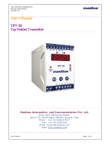
3. Front Panel Description
3.1 Keyboard and Operation
There are four keys for operation of the instruments. For understanding the
operation first of all understand the functionality of keys as shown in Fig.1.
Fig 3.1. Front Panel 409-W
MENU key: It is used to come out from the main or sub menu.
Menu + UP key is used to see mV in run mode.
ENTER key: It is used to select the desired parameter in various operating Mode.
After setting the data to proper value, by increment or decrement key, it is used to
enter the value of the selected parameter in memory.
It is used for alarm acknowledgment in run mode.
UP key: It is used to increment the parameter for selection. Value of Parameter can
be incremented by pressing this key. If the key is pressed continuously for more
than 10 counts change, the rate of increment will be made faster. This facility is to
allow faster data change for higher values.
Long press up to 7 sec will TARE the weight for SGI input.
DOWN key: It is used to decrement the parameter for selection. Value of parameter
can be decremented by pressing this key. If the key is pressed continuously for
more than 10 counts change, the rate of decrement will be made faster. This facility
is to allow faster data change for higher values.
It is used to display Gross value in run mode for SGI input.
Communication Status lamps: Lamps will blink when communication is on.
Alarm status lamps: When alarm occurs respective alarm lamp will on.

Strain Guage Indicator: 409-W
REF NO: m59A/om/501
Issue NO: 03
Page 6 of 34
4. Panel Cutout Dimension
Fig 4.1.Panel cut out for 409-W

Strain Guage Indicator: 409-W
REF NO: m59A/om/501
Issue NO: 03
Page 7 of 34
5. Sticker details
5.1 Terminal Arrangement Diagram
Fig 5.1. Terminal arrangement for 409-W
5.2 Connection diagram for SGI Input
Fig 5.2. Connection diagram for 409-W

Strain Guage Indicator: 409-W
REF NO: m59A/om/501
Issue NO: 03
Page 8 of 34
6. Configuration Guidelines
6.1 Menu Parameter List
Display
Name
Description
Default
Value
RESO
(RESO)
Resolution
Set position of Decimal Point on Display.
0 : 0
1 : .0
2 : .00
3 : .000
4 : .0000
.0
MAXMV*
(MAXMV)
Maximum Mv
range
Set mV range for resolution.
0: 15mV
1 : 30mV
2 : 75mV
3 0 m V
OFST
(OFST)
Offset
Set offset value for weight
-9999 to 9999
0 . 0
KTARE
(KTARE)
Keypad Tare
option
Set value to enable or disable Key tare
0: Disb
1: En
eN
ZTARE
(ZTARE)
Zero Tare
set to clear Tare
0: NO
1: YES
NO
STEP
(STEP)
Step value
Set steps for display increment
0: OFF
1: 2
2: 5
3: 10
O F F
Rtr
Retransmission
RET V
(rETV)
Retransmission
voltage
Retransmission Output Type
This output is according to PV input.
Zero & Span acts as Min & Max value of retransmission o/p
scale respectively.
0 : 0-10V
1 : 0-5V
2 : 1-5V
Voltage or Current is Jumper Selectable from the
Hardware.
0-10

Strain Guage Indicator: 409-W
REF NO: m59A/om/501
Issue NO: 03
Page 9 of 34
RETmA
(rEtma)
Retransmission
current
Retransmission Output Type
This output is according to PV input.
Zero & Span acts as Min & Max value of retransmission o/p
scale respectively.
0 : 4-20mA
1 : 0-20mA
Voltage or Current is Jumper Selectable from the
Hardware.
4-20mA
OPZ
(OP Z)
Output Zero
Set output zero for retransmission scaling
0.0
OP S
(OP S)
Output Span
Set output span for retransmission scaling
200.0
R MAPP
(R MAPP)
RET map
Set value for retransmission mapping
0: NET
1: Gross
0
Alarm
Alarm Logic
ATYP
(ATYP)
Alarm Type
Set which Set Point to shown in SV display in RUN mode
while device is in Auto Mode
0 : HH
1 : HL
2 : LL
LL
SEL
(SEL)
Selection for Alarm 1 & 2.
0: AL1
1: AL2
-
Al1/AL2
(AL1/AL2)
Alarm 1/Alarm 2
Set which Set Point to shown in SV display in RUN mode
while device is in Auto Mode
0 : ALRM
1 : TRIP
A LR M
LACH
(LACH)
Latch
Enable or Disable Latch
0 : YES
1 : NO
NO
HYST
(HYST)
Hysteresis
Hysteresis Value for Relay 0.000 to 0.255
1 to 255
Resolution = 0
0.1 to 25.5
Resolution = 0.0
0.01 to 2.55
Resolution = 0.00
0.1

Strain Guage Indicator: 409-W
REF NO: m59A/om/501
Issue NO: 03
Page 10 of 34
0.001 to 0.255
Resolution = 0.000
0.0001 to 0.0255
Resolution = 0.0000
OPES
(opes)
OPEN Sensor
Status
Set Control O/P & Retransmission state when Input OPEN
condition.
0 : UP
1 : DOWN
UP
ST-1
(st-1)
Set Point 1
Range Depending on PV sensor type selected
1 0. 0
ST-2
(st-2)
Set Point 2
Range Depending on PV sensor type selected
1 0. 0
RDLY
(rdLY)
Relay Delay
(For Relay)
Relay Delay is amount of time (in sec), that Relay will wait
before getting ON after the ON condition occurs.
0 to 9999 sec
0 s e c
CTRl
(CTRL)
Control Relay
Select Control Relay Status
0 : ON
1 : OFF
O FF
COM
Communication
SRNO
(srno)
Serial No
Unit ID for Modbus-RS485 Communication
1 to 247
1
BAUD
(baud)
Baud Rate
Set Modbus RS485 Communication Baud Rate
0 : 4800 (4800 bps)
1 : 9600 (9600 bps)
2 : 19.2K (19200bps)
3 : 38.4K (38400bps)
9600
PRST
(PRST)
Parity/Stop bit
Set Parity and Stop bit
0 : PNS1
1 : PNS2
2 : POS1
3 : POS2
4 : PES1
5 : PES2
PnS1
FLTR
(fltr)
Filter
Filter is time (in sec), that PV will wait before getting to its
value after filter set.
0-60 sec
0
BRHT
Brightness
Adjust Brightness of the 7-segment Display.
100

Strain Guage Indicator: 409-W
REF NO: m59A/om/501
Issue NO: 03
Page 11 of 34
(brHt)
10 to 100
F-CNT
(F-CNT)
Filter count
IIR Filter is apply for sated count only.
0-500
20
ALPHA
(ALPHA)
Alpha
Set alpha for IIR Filter.
0-100
0
M-CNT
(M-CNT)
Average Count
Moving Average Filter is apply for sated count only.
0-500
20
PASS
(pass)
Password
Set Device Password
0 to 9999
1
CAL**
Calibration
CALIB
(CALIB)
Calibration
methods
Set calibration method.
0 : S-WGT (Sample weight calibration method)
1 : TH-mV (theoretical mV calibration method)
S -W G T
RESO
(RESO)
Resolution
Set position of Decimal Point on Display.
0 : 0
1 : .0
2 : .00
3 : .000
4 : .0000
.00
1ZERO
(zero)
Zero
Can be set to any value within the Input Range & less the
SPAN Value.
0.00
SPAN
(span)
Span
Can be set to any value within the Input Range & greater
the ZERO Value.
200.00
2mV-FS
(mv-FS)
Full span mV
Can be set to any value within the input mV range.
20.000
2CALZ
(CALZ)
Calibrate zero
theory mV
Set above calibration parameters as per requirement
Press DOWN key to calibrate ZERO
Process
value
1SMP-W
(SMP-W)
Sample weight
calibration
Set above calibration parameters as per requirement,
Press DOWN key to calibrate ZERO
press UP key to calibrate SPAN
Process
value
Table 6.1
1Display only if method is S-WGT.
2Display only if method is th-mV.
Note 1: For SGI input DI is used to Tare the weight. When 24V Signal is applied
momentarily at the DI terminal, it will tare the weight.

Strain Guage Indicator: 409-W
REF NO: m59A/om/501
Issue NO: 03
Page 12 of 34
Note 2: * maximum mV read from input, select
1. 15mV for 0-15mV
2. 30mV for 0-30mV
3. 75mV for 0-75mV
Note 3: ** initial settings
Parameters
Set value
Resolution
0.00
Scaling input zero mV
0.0mV
Scaling input Display Zero
0.00
Scaling input span mV
20.0000mV
Scaling input Display Span
200.00
Table 6.2
6.2 Menu Layout for 409-W
6.3 Main Menu for 409-W

Strain Guage Indicator: 409-W
REF NO: m59A/om/501
Issue NO: 03
Page 13 of 34

Strain Guage Indicator: 409-W
REF NO: m59A/om/501
Issue NO: 03
Page 14 of 34
6.4 Calibration menu
Theoretical mV calibration method
Sample weight calibration method

Strain Guage Indicator: 409-W
REF NO: m59A/om/501
Issue NO: 03
Page 15 of 34
7. Alarm Operation
7.1 Alarm type
HH-high, very high AL1-high, AL2-very high
HL-high, low AL1-low, AL2-high.
LL-very low, low AL1-very low, AL2-low.
This setting is common for all groups.
7.2 Status of ALARM/TRIP
It will toggle between ALARM and TRIP depending up on selection in menu.
ALARM mode is further subdivided into Alarm with Latch and Alarm without Latch.
TRIP is useful when the relay is used for tripping the plant or device and it is not to
be started once again. Open condition is treated as normal condition in TRIP type.
7.3 Latching of ALARM
This is used for latching of discrete LEDs and relay status when alarm limit is
crossed. This option will keep discrete LEDs/Relay latched even after channel has
come to normal status until ENTER (ACK) key is pressed. This option can be
changed to YES or NO for enabling or disabling respectively. When configurations
of Alarms are of TRIP type, these parameters will be skipped from display. Different
conditions for the ALARM/TRIP have been mentioned in the following table 7.4,
7.5, 7.6, 7.7.
7.4 HH Logic
Fig 7.1
HH-high, very high. AL1-high, AL2-very high
AL1-High, AL2-Very High
SP2>SP1
If PV>SP1 but, less than SP2 => Relay 1- ON, Relay 2-OFF.
If PV<SP1-Hyst1 => Relay 1-OFF, Relay 2-OFF.
PV>SP2 => Relay1 and Relay2 both are ON.

Strain Guage Indicator: 409-W
REF NO: m59A/om/501
Issue NO: 03
Page 16 of 34
If PV<SP2-Hyst2 but, >SP1 => Relay 1-ON, Relay 2-OFF.
Depending up on condition set i.e. Latch Yes/No, Acknowledge Yes/No or Trip refer
table 7.4, 7.5, 7.6, 7.7.
7.5 HL Logic
HL-high,low AL1-low, AL2- high Fig 7.2.
AL1-low, AL2- High
SP2>SP1
If PV>SP2 then Relay 2-ON.
If PV<SP2-Hyst2 => Relay 2-OFF.
PV<SP1 => Relay1 ON.
If PV>SP1+Hyst1 then. Relay 1-OFF.
Depending up on condition set i.e. Latch Yes/No, Acknowledge Yes/No or Trip refer
tables 7.4, 7.5, 7.6, 7.7.
7.6 LL Logic
LL-low, low AL1- very low, AL2-low.
AL1- very Low, AL2-Low
SP2>SP1
If PV<SP1 then => Relay 1-ON, Relay 2-ON
Relay 1-ON till PV>SP1+HYS1 after that Relay 1-OFF.

Strain Guage Indicator: 409-W
REF NO: m59A/om/501
Issue NO: 03
Page 17 of 34
Relay 2-ON till PV>SP2+HYS2 after that Relay 2- OFF.
Fig 7.3.
Depending upon condition set i.e. Latch Yes/No, Acknowledge Yes/No or Trip refer
tables 7.4, 7.5, 7.6, 7.7.
7.7 Open sensor UP scale/DOWN scale
This is used to define the state of the alarms in OPEN sensor condition. It can be
configured as UP Scale or DOWN Scale by keys. This condition works if and only if
OPEN sensor condition occurs. Suppose ,UP scale has been selected and “HH”
logic is there then during OPEN sensor condition Relay 1 & 2 will be ON and Lamp
will be FLASH as shown in tables 7.4, 7.5, 7.6, 7.7. If DOWN logic is selected then
relays and Lamp will be OFF.
7.8 HH Logic
HH-high, very high. AL1-high, AL2-very high.
In this logic if “UP Scale” condition has been selected than in OPEN sensor
condition ALARM 1 and ALARM 2 will be in the ABNORMAL condition and will
work according to the following tables 7.4, 7.5, 7.6, 7.7.If “DOWN Scale” Condition
has been selected for this logic than in OPEN sensor condition ALARM 1 and
ALARM 2 will be in the NORMAL State of operation.
7.9 HL Logic
HL-high, low AL1-low, AL2-high.
In this logic if “UP Scale” condition has been selected than in OPEN sensor
condition ALARM 2 will be in the ABNORMAL condition and ALARM 1 will be in the
NORMAL condition will work according to the following tables 7.4, 7.5, 7.6, 7.7.If
“DOWN Scale” Condition has been selected for this logic than in OPEN sensor
condition ALARM 1 will be in the ABNORMAL condition and ALARM 2 will be in the
NORMAL condition and will work according to the following tables.

Strain Guage Indicator: 409-W
REF NO: m59A/om/501
Issue NO: 03
Page 18 of 34
7.10 LL Logic
LL-low, low AL1-very low, AL2-low.
In this logic if “UP Scale” condition has been selected than in OPEN sensor
condition ALARM 1 and ALARM 2 will be in the NORMAL condition and will work
according to the following tables 7.4, 7.5, 7.6, 7.7.If “DOWN Scale” Condition has
been selected for this logic than in OPEN sensor condition ALARM 1 and ALARM 2
will be in the ABNORMAL State of operation.
7.11 Process value on Display
PV>105% OR
PV< -5% OR PV
open
-5%
0%
100%
105%
zero
span
mV
group
OPEN
UNDER
-19999
99999
OVER
-19999
99999
15mV
OPEN
UNDER
-19999
99999
OVER
-19999
99999
30mV
OPEN
-250
0
5000
5250
0
5000
75mV
OPEN
-250
0
5000
5250
0
5000
30mV
Table 7.1.
Note: If maximum value of zero and span then process value will display OVER/UNDER
message until value crosses 5% of selected group of mV(15mV or 30mV or 75mV). If
value of zero and span is less than maximum value of zero and span then process value
will display open message until value crosses 5% of selected group of mV (15mV or 30mV
or 75mV). Process value greater than5% of selected group of mV (15mV or 30mV or
75mV) then display will show OPEN message. Retransmission o/p will follow 5% of
display range and then it will give fixed o/p depending up on input OPEN sensor selection.
7.12 Retransmission output during OPEN sensor
I/P
0-20 mA O/P
4-20 mA O/P
UP Scale O/P
DW Scale O/P
UP Scale O/P
DW Scale O/P
SGI
21.00
0.0
20.8
3.2
Table 7.2.
I/P
0-10 V O/P
0-5 V O/P
1-5 V O/P
UP Scale
O/P
DW Scale
O/P
UP Scale
O/P
DW Scale
O/P
UP Scale
O/P
DW Scale
O/P
SGI
10.50
0.0
5.25
0.0
5.20
0.80
Table 7.3.
Above mention value in the table 7.2, 7.3 will come only after calibration for specific o/p
type i.e. Voltage/Current.

Strain Guage Indicator: 409-W
REF NO: m59A/om/501
Issue NO: 03
Page 19 of 34
7.13 Relay Delay
Relay delay is the parameter used to set the delay (second) in the operation of
relays (both 1&2).Minimum value of delay is 0(second) and maximum value 9999
(second) can be configured using keyboard.
7.14 Control Relay
Control relay “OFF” then relay will function according to the condition mention in the
following tables. Control relay “ON” then functioning of relay will be just opposite to
the condition mention in the table. Lamp functioning will be as mention in the table
i.e. no change in the LED status.
Alarm AL1 (Momentary Alarm): when in abnormal condition ACK not pressed.
Condition
Normal
Abnormal
UP
DOWN
ACK**
Normal*
ACK***
High
Alarm
Latch
(Yes)
LAMP
OFF
FLASH
FLASH
OFF
FLASH
OFF
RELAY
OFF
ON
ON
OFF
OFF
OFF
Alarm
Latch
(No)
LAMP
OFF
FLASH
FLASH
OFF
OFF
OFF
RELAY
OFF
ON
ON
OFF
OFF
OFF
Trip
LAMP
OFF
FLASH
OFF
OFF
FLASH
OFF
RELAY
OFF
ON
OFF
OFF
ON
OFF
Low
Alarm
Latch
(Yes)
LAMP
OFF
FLASH
OFF
FLASH
FLASH
OFF
RELAY
OFF
ON
OFF
ON
OFF
OFF
Alarm
Latch
(No)
LAMP
OFF
FLASH
OFF
FLASH
OFF
OFF
RELAY
OFF
ON
OFF
ON
OFF
OFF
Trip
LAMP
OFF
FLASH
OFF
OFF
FLASH
OFF
RELAY
OFF
ON
OFF
OFF
ON
OFF
VLow
Alarm
Latch(
Yes)
LAMP
OFF
FLASH
OFF
FLASH
FLASH
OFF
RELAY
OFF
ON
OFF
ON
OFF
OFF
Alarm
Latch(
No)
LAMP
OFF
FLASH
OFF
FLASH
OFF
OFF
RELAY
OFF
ON
OFF
ON
OFF
OFF

Strain Guage Indicator: 409-W
REF NO: m59A/om/501
Issue NO: 03
Page 20 of 34
Table 7.4.
Alarm AL2 (Momentary Alarm): when in abnormal condition ACK not pressed.
Table 7.5.
Alarm AL1 (Maintained Alarm): when in abnormal condition ACK is pressed.
Trip
LAMP
OFF
FLASH
OFF
OFF
FLASH
OFF
RELAY
OFF
ON
OFF
OFF
ON
OFF
Condition
Normal
Abnormal
UP
DOWN
ACK**
Normal*
ACK***
VHigh
Alarm
Latch(Yes)
LAMP
OFF
FLASH
FLASH
OFF
FLASH
OFF
RELAY
OFF
ON
ON
OFF
OFF
OFF
Alarm
Latch(No)
LAMP
OFF
FLASH
FLASH
OFF
OFF
OFF
RELAY
OFF
ON
ON
OFF
OFF
OFF
Trip
LAMP
OFF
FLASH
OFF
OFF
FLASH
OFF
RELAY
OFF
ON
OFF
OFF
ON
OFF
High
Alarm
Latch(Yes)
LAMP
OFF
FLASH
FLASH
OFF
FLASH
OFF
RELAY
OFF
ON
ON
OFF
OFF
OFF
Alarm
Latch(No)
LAMP
OFF
FLASH
FLASH
OFF
OFF
OFF
RELAY
OFF
ON
ON
OFF
OFF
OFF
Trip
LAMP
OFF
FLASH
OFF
OFF
FLASH
OFF
RELAY
OFF
ON
OFF
OFF
ON
OFF
LOW
Alarm
Latch(Yes)
LAMP
OFF
FLASH
OFF
FLASH
FLASH
OFF
RELAY
OFF
ON
OFF
ON
OFF
OFF
Alarm
Latch(No)
LAMP
OFF
FLASH
OFF
FLASH
OFF
OFF
RELAY
OFF
ON
OFF
ON
OFF
OFF
Trip
LAMP
OFF
FLASH
OFF
OFF
FLASH
OFF
RELAY
OFF
ON
OFF
OFF
ON
OFF
Condition
Normal
Abnormal
UP
DOWN
ACK**
Normal*
ACK***
Alarm
Latch(Yes)
LAMP
OFF
FLASH
FLASH
OFF
STEADY
STEADY
OFF
RELAY
OFF
ON
ON
OFF
ON
OFF
OFF
/