Page is loading ...


1 02/08
MALAGUTI S.p.A.
Via Emilia 498, 40068 - San Lazzaro di Savena (BO) - ITALY
Tel. 051.62.24.811 - Fax 051.69.47.782
e-mail: inf[email protected] - http: // www.malaguti.com
FOREWORD
• The present manual specifically addresses to specialised technical personnel (MALAGUTI authorised service centres and single motor mechanics) and contains all the
service interventions indicated by the Manufacturer until the publishing of this document.
• Some basic technical information has been intentionally omitted as it is considered to be common knowledge.
• Additional information is available in the SPARE PARTS CATALOGUES of each model.
• It is important to read all the general information before going through the manual to the specific topics and the maintenance operations to be carried out on the motor-bike in
order to make sure the topics, the technical and safety concepts are clearly understood and the manual can be used as a sure reference text.
• All checks, maintenance, repairs or replacements of spare parts in our motor-bikes are to be performed by skilled and expert technical personnel with specific experience
in state-of-the-art technology and full knowledge of the quickest and most rational procedures, technical characteristics, setting values, tightening torques and information as
to which may only be properly and exhaustively provided by the manufacturer.
• It is important to adhere strictly to the following instructions. Any operation carried out carelessly or not carried out at all may lead to personal injury, damage to the motorcycle
or simply to complaints.
MALAGUTI S.p.A. reserves the right to make any changes and modifications hereto it deems necessary without prior notice.
For further information and details, please contact MALAGUTI S.p.A. Servicing or Engineering Division.

2 02/08
NOTES FOR EASY CONSULTATION
ABBREVIATIONS
EDITING SYMBOLS:
• Symbols have been provided for quick and easy reference, identifying situations requiring utmost attention or providing practical suggestions or simple information.
• These symbols may appear next to a text (in which case they refer solely to the text itself), next to a figure (in which case they refer to the topic illustrated in the figure and
to the relative text), or at the top of the page (in which case they refer to all the topics dealt with in the page).
NOTE - The meaning of the symbols should be duly memorised as their scope is to avoid having to repeat basic technical concepts or safety recommendations.
Cs Torque wrench setting
D Nut
Dx Right
F Picture
G Gasket
P Page
R Washer
Sx Left
T Ta bl e
V Screw
TECHNICAL DICTIONARY
V = (DC) Direct current (battery supply)
V ~ (AC) Alternating current (flywheel supply)
A : Ampere Unit of measurement of the electrical current
W : Watt Unit of measurement of the electrical power (product of Volts and Amperes; A x V = W)
ΩΩ
ΩΩ
Ω : OHM Unit of measurement of the electrical resistance
< Lower
≤≤
≤≤
≤ Lower or equal
> Higher
≥≥
≥≥
≥ Higher or equal
bar Unit of measurement of pressure
N * m Newton/metre Unit of measurement of the tightening torque

3 02/08
M
R
SYMBOL LIST
CAUTION!
Recommendations and
precautions regarding rider
safety and motor vehicle
integrity.
WARNING! Situations entailing
the risk of personal injury to
maintenance or repair
mechanics, other workshop
personnel or third parties, or
damage to environment,
vehicle or equipment
FIRE HAZARD.
Indicates operations which
may constitute a fire
hazard
RISK OF
EXPLOSION
Indicates operations
which may constitute a
risk of explosion
TOXIC FUMES
Indicates a possibility of
intoxication or inflammation
of the upper respiratory
tract
WARNING!
Danger of crashing
arms
SAFETY GLOVES
These operations require
the use of safety gloves
IMPORTANT
This topic requires special
attention
GENERAL SERVICE
PERSONNEL
Skilled electronic or
mechanical technician.
MECHANICAL
MAINTENANCE
Operations to be performed
only by an expert mechanic
ELECTRICAL
MAINTENANCE
Operations be performed
only by an expert electrical/
electronic technician
IGNITION KEY ON
(ON position)
PRESENT MANUAL
Information on the
present manual
“ENGINE” SERVICE
MANUAL
Indicates information which
may be obtained by
referring to said catalogue
SPARE PARTS
CATALOGUE
Indicates information which
may be obtained by
referring to said catalogue
DISASSEMBLY
OPERATIONS
ASSEMBLY
OPERATIONS
SYMMETRICAL
OPERATIONS
Operations that must be
carried out also on the other
side of the unit or
component.
EMPTY THE CIRCUIT
REPLACE WITH NEW,
ORIGINAL SPARE
PA RT S
IDLING ENGINE
Switch on the engine, at
idling speed, to perfom
these interventions.
ENGINE OFF
Indicates operations to
be performed with
engine off
POWER OFF
Indicates that negative
pole is to be disconnected
from the battery before
performing the operation
NO!
Operations to be
absolutely avoided
OIL
COOLANT
FUEL

4 02/08
Before any servicing, make sure that the vehicle is perfectly stable.
The front wheel should preferably be anchored to fixture, which is integral with the lift platform.
GENERAL WORK PROCEDURES
• The recommendations given hereafter are aimed at ensuring maximum work safety as well as at considerably reducing the risk of accidents, personal injury, equipment
damage and idle times, and should therefore be strictly adhered to.
• Always listen with attention to the customer’s opinion and complaints about the motor-bike operation, asking specific questions in order to have a complete understanding of
all the symptoms and identify with good approximation the real causes of the trouble. The present manual provides the technical information and the basic indications on the
intervention procedures but these have to be integrated with the personal expertise.
• We suggest planning the service interventions in order to avoid any waste of time or downtime. Try to reduce as much as possible the operations necessary to reach the
components that needs repairing.
• Prepare the components that are likely to be replaced and all the original spare parts you may need.
• Use only the original spare parts.
• Mark the components that may be mis-placed during re-assembly operations.
• Only use quality tools and equipment.
• Only use equipment conforming to EU Directives for lifting the vehicle.
• During operations, always keep tools and equipment at hand, possibly laying them out according to the sequence in which they are to be used. Absolutely avoid putting them on the
vehicle itself, out-of-sight or in poorly accessible places.
• Always keep the work area neat and clean.
• When tightening screws or nuts, start with the larger diameter or inner fasteners, and tighten them in progressive “pulls” using a “criss-cross” pattern.
• The torque settings specified in the manual refer to the “final torque”, which must be attained progressively by steps.
• Preferably use open-end box wrenches by “pulling” and not “pushing”.

5 02/08
• Before carrying out any operation, wait for all parts to cool down.
• For operations requiring two mechanics, make sure that the various steps to be performed by each of them are clearly defined and co-ordinated beforehand.
• Make sure that each component has been properly mounted before proceeding with assembling the next one.
• Always replace gaskets, O-rings, circlips and split pins at every refitting.
• Only use screwdrivers with sizes suitable to the screws to be loosened or tightened.
Never use open flames for any reason.
Never leave open containers or containers not suitable for holding fuel in passageways, close to heat sources, etc.
Never use petrol to clean the vehicle or the floor of the workshop. Always use low flash point solvents to clean the vehicle components.
When welding, make sure that there are no flammable liquids in the vicinity.
Never suck from or blow into the fuel pipe.
Never leave the engine running in closed or poorly ventilated areas.
Do not use fuses with a higher rated capacity than indicated: this may cause severe damages to the electrical system and burn a fire as a conse-quence of short circuit.
• Make sure that the vehicle is stable and not to have to take on awkward working positions.
• Never reuse old gaskets or circlips.
• Never use a screwdriver as a lever or chisel.
• Never use pincers to loosen or tighten screws or nuts because, in addition to not providing a sufficient clamping force, they may also damage the screw head or nut hexagon.
• Never tap the wrench with a hammer or other similar tool to loosen or tighten screws and nuts.
• Never attempt to increase the lever arm by fitting a tube into the wrench.

6 02/08
CONTENTS
DESCRIPTION P.
RIGHT RADIATOR - LEFT RADIATOR 38
ELECTRICAL FAN RADIATOR - EXPANSION RESERVOIR - THERMAL EXPANSION VALVE 39
KEY SWITCH - DASHBOARD PANEL 40
LEG PROTECTOR 41
UPPER HANDLEBAR COVER - ACCESSES 43
FRONT AND REAR HANDLEBAR COVER - ACCESSES 44
HANDLEBAR - BRAKE MASTER CYLINDERS 45
DRIVER SEAT - ACCESSES 46
PASSANGER SEAT - CUSHION DRIVER SEAT - GRAB HANDLE 47
HELMET COMPARTMENT 48
ACCESSES - DIRECTION INDICATORS AND TAIL LIGHTS 48
REAR FAIRING 49
TAIL LIGHTS 50
SIDE REACH - VOLTAGE RECTIFIER 51
COOLANT PUMP - COIL 51
RELAY HOLDER 52
ACCESSES - ELECTRONIC INJECTION ECU THROTTLE BODY 53
BATTERY COMPARTMENT - ACCESSES 54
FUEL TANK 55
AIRBOX 57
FRONT MUDGUARD - FRONT WHEEL - WHEEL SPINDLE 58
(FRONT BRAKE) DISCS - FRONT WHEEL - REASSEMBLY 59
BRAKE CALLIPERS - FRONT CALLIPER REPLACEMENT AND DISASSEMBLY 60
LOWER FAIRING MUDGUARD - FORK 63
STANCHION GROUP - STANCHION DISASSEMBLY - CHECK THE OIL LEVEL IN THE STANCHION 63
FRONT FORK OIL REPLACEMENT 64
COMPLETE FORK 64
EXHAUST - EXHAUST MANIFOLD 65
LAMBDA SENSOR - REMOVAL - REASSEMBLING 66
REAR SHOCK ABSORBERS 67
REAR ARM - SHOCK ABSORBER SUPPORTING PLATE 68
REAR CALLIPER - REAR CALLIPER DISASSEMBLY 69
REAR WHEEL - (REAR BRAKE) DISC ENGINE 71
ENGINE REASSEMBLY - ENGINE MOUNT 72
ANTI-VIBRATION CONNECTING RODS - ENGINE MOUNT 73
SUBFRAME 74
UPPER SUBFRAME - SIDE SUBFRAMES - CENTRAL ALUMINIUM FRAME 75
FRAME DIMENSION CHECK 76
CABLE POSITIONING, “PIPE SYSTEM” AND ANCHORING TIES 77
DESCRIPTION P.
SPECIFICATIONS 7
IDENTIFICATION DATA: FRAME N° / ENGINE N° - TYRES 8
MAINTENANCE TABLE 9
LUBRICANT TABLE 10
FUEL TANK - COOLANT TANK 11
BLEEDING, COOLING CIRCUIT 12
BLEEDING OF THE LEFT SIDE - BLEEDING OF THE RIGHT SIDE 12
ENGINE OIL 13
CHECK THE OIL LEVEL - TOPPING UP 13
CHANGE ENGINE OIL 14
TRANSMISSION OIL - CHECK THE LEVEL - RENEW 15
BRAKE OIL - CHECK - CHANGE 16
BRAKING SYSTEM BLEEDING - INTEGRAL SYSTEM 17
CHECK THE LEVEL OF THE BRAKE LIQUID - FRONT LEFT CALLIPER 17
CHECKING BRAKE PADS AND DISCS - BRAKE PADS 18
REPLACING THE BRAKE PADS - DISCS 18
FORK - CHECK THE OIL LEVEL IN THE STANCHION 19
FRONT FORK OIL REPLACEMENT 19
REAR SHOCK ABSORBER ADJUSTMENT - STEERING 20
HANDLEBAR ADJUSTMENT 20
LOCATION OF THE MAIN ELECTRICAL ELEMENTS 21
INSTRUMENT BOARD 23
KEY SWITCH - HANDLEBAR LOCK 24
LOCKING - DISENGAGING 24
STARTING THE ENGINE 24
LIGHTING SYSTEM - LAMPS 25
ADJUSTING THE BEAM LIGHT 26
FUSES - GENERAL PROTECTION FUSE AND CHARGE PROTECTION FUSE 27
BATTERY ASSEMBLY - CHARGE BATTERY 28
SPARK PLUG - REMPLACE 29
PROCEDURES FOR DISMANTLING AND REMOVING COMPONENTS 30
REASSEMBLY NOTE - CENTRAL FAIRING - REAR VIEW MIRRORS 30
FRONT DIRECTION INDICATORS (BULB CHANGE) 30
ACCESSES - REPLACING THE FRONT PARKING LIGHT 31
DASHBOARD - BRAKING DISTRIBUTOR - HORN 32
AIR GRID - WINDSCREEN - FRONT FAIRING 33
ACCESSES - IMMOBILIZER ECU 35
SIDE STAND SWITCH - FUEL SUPPLY PUMP 36
RADIATORS 37

7 02/08
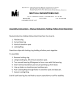
DIMENSIONS
Wheel base (A) m .......................................................................................1,490
Max. length (B) m........................................................................................2,200
Max. width (C) m .........................................................................................0,930
Max. height (D) m........................................................................................1,470
Kerb weight kg ...............................................................................................230
Max. load with rider, passenger and luggage kg..............................................180
CAPACITY
Engine oil cm3 ........................................................................................... 1700*
Transmission oil cm3 ................................................................................... 250*
Fuel tank (total).............................................................................................. 14*
ENGINE: single-cylinder, four-valve
Valves type............................................................................. PIAGGIO M34CM
n° Cylinders ...................................................................................................... 1
Bore x stroke mm .................................................................................. Ø 94x71
Capacity cm3.................................................................................................493
Compression ratio ............................................................................... 10.5 ± 0.5
Cooling........................................................................................................ liquid
Starting system ............................................................................electric starter
Greasing system.................................................................................. wet sump
SPARK PLUGS
Type ..............................................................................................NGK CR7EKB
TRANSMISSION
Automatic speed variator with expandable pulleys, V-belt, automatic
dry centrifuge clutch, reduction gear and transmission
compartment with forced circulation cooling system.
FUEL SYSTEM
Electronic injection with electrical fuel pump.
Fuel: unleaded petrol.
ELECTRONIC IGNITION
High efficiency, inductive type coupled with the injection system,
variable advance and separate HV coil.
BRAKES
The braking system is hydraulically operated and features double front disc (2
discs with a diam. of 270 mm) and rear disc (260 mm diam. disc) with braking
distribution system. The brakes are operated as follows:
Left lever: rear lever + front lever (right hand side of the vehicle)
Right lever: front brake (left hand side of the vehicle)
CHASSIS
“V-Box” type, composed of a double pressure die cast shell made of aluminium,
coupled, on the front and rear sides, to a steel pipe frame.
SUSPENSIONS
Front: hydraulically controlled fork with two Ø 41 mm rods.
Stroke: 120 mm
Rear: 2 hydraulic shock absorbers with adjustable preloading spring.
BATTERY
12V, 14Ah, maintenance-free.
TIRES
Front: 120/80 - 16 60 S
Rear: 150/70 - 16 68 S
*
Indicative Value
SPECIFICATIONS
F. 1

8 02/08
TYRES
Type: Tubeless (without inner tube)
It is possible to use tyres with load and speed indexes that are higher
than or identical to those indicated.
It is however necessary for speed indexes to be identical for both
tyres. Use only tyres with the relevant type approval.
Tyre inflation pressure must be adjusted while the tyre is at ambient
temperature.
150/70 - 16” - 68S
120/80 - 16” - 60S
2.3 2.3 2.3
(33.4) (33.4) (33.4)
2.3 2.3 2.3
(33.4) (33.4) (33.4)
B
F. 2
F. 3
A
• To read the vehicle’s identification number (VIN) (A) lift the saddle
and remove the cover located in front of the helmet compartment.
• Engine identification data are located on the left-hand engine crankca-
se (B).
Any alteration to the vehicle identification data is pursued
by the Law.
Minimum tread depth is 2 mm.
• There are T.W.I. marks all around the tyre
sides. These correspond to tyre wear
indicators situated in the tyre’s tread; if
there is no difference between the
thickness of the tyre wear indicators and
the tread depth, the tyre must be replaced.
F. 4
X
Y
IDENTIFICATION DATA: FRAME N° / ENGINE N°

9 02/08
MAINTENANCE TABLE
NOTE - Maintenance operations should be performed more frequently if the vehicle is used in rainy weather, in dusty places or on rough
terrain.
Due to their simplicity, checks with no asterisk CAN also be carried out by technicians not authorised by MALAGUTI, but under
their direct responsibility.
Nr. : coupon
: check
: clean
: adjust
: replace

10 02/08
LUBRICANT TABLE
NOTE - Use only recommended products.
LUBRICANTS
ENGINE OIL (4-STROKE TYPE) FORMULA EXCEL SAE 5W40
ENGINE TRANSMISSION OIL ZC 90
AIR FILTER LUBRICANT AIR FILTER OIL
RADIATOR FLUID Q8 LONG-LIFE RED
BRAKE CIRCUIT FLUID BRAKE FLUID DOT 4
FORK ROD OIL FORK OIL

11 02/08
FUEL TANK
To access the fuel tank, proceed as follows:
• Place the vehicle on the centre stand.
• Remove the ignition key from the ignition block.
• Open the door (A) in front of the seat, by acting on the lever
(B).
• Insert the ignition key, remove the cap (B) and refuel the
tank.
• After refuelling, immediately remove any possible traces
of fuel from the vehicle body, since fuel may deteriorate
the vehicle’s outer surfaces.
Use UNLEADED PETROL.
F. 5
F. 7
COOLANT TANK
• To access the engine coolant tank, open the glove compartment (A) located at the
centre of the lower fairing and remove the plastic cover (B). Owing to the particular
position of the tank, the level of coolant, with respect to the minimum and maximum
level marks, can be checked through the grid under the upper fairing, on the front
side of the vehicle. Use the coolant prescribed in this manual - or one having
identical characteristics - for any topping up. Never unscrew the tank cap (T) when
the engine is warm, so as to avoid burnings. Do not top up with water, except in
emergency situations and in this case, have the entire contents of the tank replaced
by a suitable product as soon as possible.
A
*
Indicative Value
B
T
14*
3*
F. 6
A
B
C
FUEL TANK Litres
TOTAL TANK CAPACITY
RESERVE

12 02/08
BLEEDING, COOLING
CIRCUIT
To bleed the air, with the
circuit completely drained
from the coolant, proceed as
follows:
BLEEDING OF THE LEFT
SIDE
• Remove the cap on the
bleeding coupling (A).
• Fit a tube in the coupling
(A) of the bleed nipple on
the cylinder head.
• Refill the expansion reser-
voir with coolant, as descri-
bed: (P. 11).
• Release and remove the
filler (B).
• Pour some coolant in the
main radiator (left).
• Slacken the coupling (A)
and go on refilling the main
radiator until some liquid
would drip off the tube (with
regular flow).
• Now, close the bleed nipple
(coupling - A) and fill in up
to the rim of the main
radiator.
• Slacken the bleed screw (C),
until some liquid drips off with
regular flow.
• Close the screw and top up
the liquid.
• Open the bleed nipple on the
cylinder head and check the
tubes for liquid dripping,
showing that the bleeding
has been correctly carried
out.
• Close the coupling (A) back.
F. 7/a
F. 7/c
BLEEDING OF THE RIGHT
SIDE
•Slacken the bleed screw (D),
until some liquid drips off with
regular flow.
• Close the screw and top up the
liquid in the main radiator.
• With the help of an assistant,
slightly tilt the vehicle on the ri-
ght side and, keeping it in this
position, slightly slacken the
screw (D), to let any remaining
air out of the right radiator.
• Tighten the bleed screw (D),
F. 90/a
which act as the ground screw.
• Open the bleed nipple on the cylinder head and check the tubes for liquid dripping,
showing that the bleeding has been correctly carried out.
• Close the coupling (A), remove the tube and fit the cap.
• Check the main radiator is completely refilled with coolant; top up and refit the filler
(B), if necessary.
F. 7/d
F. 7/b
C
A
B
D

13 02/08
ENGINE OIL
• As far as four-stroke engines are concerned, engine oil is used to lubricate distribution components, base bearings
and thermal unit. An insufficient amount of oil can seriously damage the engine.
• In all four-stroke engines, deterioration of the oil and a certain consumption are to be considered normal.
CHECK THE OIL LEVEL
This check should be performed when the engine is cold, as described below:
1) Park the vehicle on flat ground and put it on its centre stand (even a slight inclination may alter results).
2) Unscrew the cap/dipstick (A), dry it with a clean cloth and refit it, wrenching it firmly in place.
3) Remove the cap/dipstick and make sure the level falls betwe en the MAX and MIN notches; if necessary, top up
with Q8 FORMULA EXCEL SAE 5W40 oil.
The MAX level notch corresponds to quantity of about 1700 cm3 of oil in the engine.
If you need to check the level when the engine is warm, remember that the level line will be lower. It is best to wait at least 10 minutes from stopping the
engine in order to have a correct reading.
The vehicle features a control system that activates the “LOW OIL PRESSURE” alarm signal of the digital instrument board in the event of trouble.
TOPPING UP
Before topping up, check the oil level and in no case allow the level to rise above the MAX notch.
• Topping up to level falling between the MIN and MAX marks means using about 400 cm3 of oil.
Never allow the level to rise above the MAX mark! This may seriously damage the engine, due to excessive internal pressure.
• Every 3000 km, it is recommended to have the engine oil checked.
ALARM MESSAGE (LOW OIL PRESSURE)
The digital instrument board features a control system displaying a “LOW OIL PRESSURE” message (B - § 3.11.6). The message appears when the vehicle is turned on to
signal that the check function is working. The message disappears automatically after a few seconds. It will only reappear during vehicle use if there is actually a low oil
pressure problem.
If the message appears when you are braking, when the engine is idling or when curving, stop the vehicle, check the oil level and top up if necessary.
Every 3,000 km, the message OIL is displayed on the digital instrument board. This warning light indicates that it is time to change the engine oil. This
warning light is displayed on the instrument board until the indicated operation is carried out.
Waste oil is toxic for the environment, therefore we suggest you contact an Authorised Service Centre for disposal according to the rules in force.
every 3000 km or 6 months
F. 8
A

14 02/08
every 6000 km or 12 months
CHANGE ENGINE OIL
• The engine must be emptied by letting the oil flow from the drainage cap (B) of the filter beside the transmission. To facilitate drainage, loosen the cap/dipstick (A F. 8/a).
• Unscrew the cartridge filter (C) and remove it. Fit a new filter, and lubricate the O-rings with engine oil. Since a certain amount of oil remains in the circuit, fill through the cap
(A) using about 1500 cm3 of oil. Start the vehicle, let it run for a few minutes and turn it off: after 5 minutes, check the level and top up but never above the MAX mark.
F. 9
B
F. 9/a
C
The cartridge filter must be replaced every time the oil is changed. For topping up and replacement use Q8 FORMULA EXCEL SAE 5W40 oil.
Letting the engine run with an insufficient amount of lubricant or with the wrong types of lubricant causes wear to moving parts and can in the long run
cause serious damage.
Waste oil contains polluting substances. Have oil replaced by an Authorised Service Centre that will also dispose of waste oil in accordance to the law.
F. 8/a
A

15 02/08
Max
Min
TRANSMISSION OIL
CHECK THE LEVEL
1) Place the vehicle on a level surface on its centre stand.
2) Unscrew the dipstick (A), clean it and refit it, wrenching it tightly.
3) Pull it out again and check that the oil level is between the MIN and MAX notches.
4) If the level is insufficient, top up until you almost reach the MAX notch.
5) Fill the crankcase with this type of oil: Q8 ZC 90
Crankcase capacity approx.: 250 cm3
RENEW
• Carry out the operations described above at points 1-2, without refitting the dipstick; then put a container under the
engine crankcase and unscrew the drainage screw (B), paying attention to the gasket.
• Let oil flow into the container (pay attention to avoid scorching).
• Refit the drain plug with gasket and fill with approximately 250 cm3 of new oil (Q8 ZC 90), then refit the cap and
dipstick (A).
• Now repeat checks 3-4-5. If the drainage screw gasket is damaged, replace it.
Regularly check for oil leakages near the drain plug at the rear wheel.
every 6000 km or 12 months
after the first 1,000 km and every 24,000 km
F. 10
F. 11
A
B

16 02/08
MIN
S
CHANGE
If the fluid features traces of dirt, debris or water, it must be replaced. A soft and spongy feeling in the brake lever can indicate the presence of air in the
circuit.
CHECK
• The visual check should be made through the sight glass (S) of the tanks: front
brake (A) and rear brake (B), when the vehicle is on level ground and perfectly
upright.
• The oil should be at 3 mm from the bottom edge of the sight glass.
BRAKE OIL
When topping up, never use more than one oil.
F. 12
every 30 days
every 12.000 Km or 24 months
A
B
MIN
S
F. 13

17 02/08
BRAKING SYSTEM BLEEDING
INTEGRAL SYSTEM
Put the vehicle on firm and level ground.
• Remove the cover of the oil pump tank (left-hand side), releasing the two screws, so as to top up the liquid.
NOTE - The left brake lever allows the front right brake calliper and the rear brake calliper to be controlled interlockedly
at the same time.
To bleed the circuit of the integral system, first bleed the rear brake calliper.
• Fill in the left brake liquid tank up to the maximum level.
• Remove the rubber cap (A) from the bleed screw (B) and fit the rubber hose to collect the brake liquid.
• Operating the left brake lever, charge and pressurise.
• Keeping the left brake lever operating, slacken the bleed screw to let the air out. Then, tighten the bleed screw (B).
• Repeat the operation until only brake liquid is let out of rubber hose.
• These operations should be repeated for the front right calliper.
• Restore the level of the brake liquid in the sump.
During the bleeding, avoid the contact between the brake liquid and the bodywork, to avoid damages. Moreover, during the bleeding of the brake callipers,
avoid the contact between the liquid and the brake discs or the brake pads. Failure to observe this rule may affect the functions and the efficiency of the
braking system. If, during the bleeding, more air would come out, check all of the couplings: if they do not show any malfunctioning, look for the entrance
of the air in the different seals of the pump and in the pistons of the calliper.
During this operation, oil may leak from the bleed screw on the calliper and on the disc: if so, carefully dry the calliper and degrease the disc.
CHECK THE LEVEL OF THE BRAKE LIQUID (P. 16)
FRONT LEFT CALLIPER
• To bleed the front left calliper, operate the right brake lever.
F. 14
B
A
B
12 ÷ 16

18 02/08
CHECKING BRAKE PADS AND DISCS
BRAKE PADS
Check front and rear brake pads and discs for wear
every 2,000 Km.
• Visually check the thickness of the brake pads as shown
in the picture.
The minimum thickness of the brake pad lining should
not be thinner than 2 mm.
• Replace the brake pads in case their thickness is below
the allowed limit or they are damaged.
REPLACING THE BRAKE PADS
F. 1 7
F. 15
F. 1 6
DISCS
Check the discs for wear and replace if necessary (service limit 4.5 mm).
In case of abnormal wear or signs of scoring, carry out grinding.
For instructions on how replacing the front and rear brake pads please refer
to pages 60 and 61.

19 02/08
FORK
CHECK THE OIL LEVEL IN THE STANCHION
• In there case if the “limit switch” of the front fork or irregular noise, check the oil
level inside the fork stems by removing the stems, as shown in the picture, and
follow the instructions at page 63.
• Bring to the limit (downwards) the leg, keeping it in perfect vertical position.
• Using a meter or the stick of a gauge, check the proper oil level, which should be at
mm 123 from the upper edge of the leg.
• If necessary, top up with oil: Q8 FORK OIL
F. 18
V
V
FRONT FORK OIL REPLACEMENT
• Place a suitable container under the stanchion and remove the screw (V).
• Allow as much oil as possible to drain out.
• Disassemble the stanchions, as previously described.
• Turn over the stanchion, to let the remaining oil drain out.
The hydraulic oil is corrosive and may cause personal damages.
Do not dispose of spent oil in the environment.
• Refit the drain screw (V).
• Carefully pour the new oil in the leg.Carefully pour the new oil in the leg.
• Check the oil level, as previously described.
• Refit the components of the legs and the legs themselves on the motorcycle.
Quantity per leg 385 cc.
/