Page is loading ...

1
INSTALLATION &
OPERATION
MANUAL
Read all instructions and warnings before installing and using.
This manual must be delivered to the end user of this equipment.
IMPORTANT:
INSTALLER:
2015 FORD F-150 NO-DRILL INSTALLATION OF
C3100 SPEAKER (S)
2015 FORD F-150
C3100 SPEAKER INSTALLATION
Table of Contents:
Page No: Description:
1. Pre-installation preparation
2. Installation instructions
3. Installation notes
4. Warranty Information
Preparation for Installation:
Hardware provided for this installation will help prevent galvanic corro-
sion from taking place due to dissimilar metals.
1. The mounting of C3100 speaker using the clamp-on design bracket will avoid the need
for drilling into the aluminum body of the new Ford F150 truck.
2. The Loop and Pile Pads at the top of the assembly will prevent lateral movement of the
unit once the bracket system is tightened into position.

2
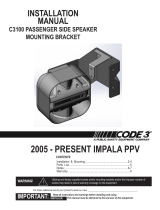
Locate areas under the truck front end at the cross member as pictured.
Two speaker bracket systems can be mounted on this cross member.
Side view of Pas-
senger side bracket
installation:
Installation Procedure:
Passenger Side:
1. Install Speaker housing onto L bracket with the
housing facing the opposite direction of the short
leg on the bracket.
2. Install (2) Hook and Pile pad sections on under-
side surface of short leg of the bracket (either half
of the two piece pad system is acceptable)
3. Locate the area for the L bracket to be installed
over the truck cross frame by sliding the short leg
of the bracket between the cross frame and the
splash guard above the frame. (between the guard
fasteners and the outside end of the cross frame.)
Mark the area for the second half of the Hook and
pile connectors to be installed. (see g 1)
4. From the front side of the cross member- Slide
the L bracket back off the frame and now install
the second half of the hook and pile pads to the
top of the cross frame in the area marked.
5. Pushing the short leg upward against the splash
guard - re insert the L bracket over the frame
member and seat the hook and pile connecting
pads into each other.
6. Insert tab of clamp bracket into L bracket slot
and rotate the clamp over the bottom of the cross
frame.
7. Install (2) 1/4- 20 nuts over studs on L bracket
and tighten while maintaining upward pressure on
the clamp assembly.
Installation Procedure:
Driver Side:
1. Locate area forward of the manifold
2. Mark this area for the hook and pile pad instal-
lation on the top of the cross frame.
3. Install Speaker housing onto L bracket with
the housing facing the opposite direction of the
short leg on the bracket.
4. Install (2) Hook and Pile pad sections on un-
derside surface of short leg of the bracket (either
half of the two piece pad system is acceptable)
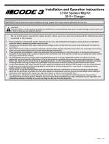
View looking up
at Passenger side
of truck frame.
mark area for
pads to be in-
stalled on top of
cross frame.
FWD
clamp
bracket
g 1.
g 2.
manifold

3
Notes:
Installation Procedure:
Driver Side continued:
5. Install opposite sides of the Hook and Pile pads on
the top of the cross frame rail where the bracket is to
be installed.
6. Pushing the short leg upward against the splash
guard - re insert the L bracket over the frame member
and seat the hook and pile connecting pads into each
other.
7. Insert tab of clamp bracket into L bracket slot. The
clamp bracket must be manuvered under manifold
lines.
8. Rotate the clamp bracket over the bottom of the
cross frame and seat over studs on L bracket..
9. Install (2) 1/4- 20 nuts over studs on L bracket and
tighten while maintaining upward pressure on the
clamp assembly.
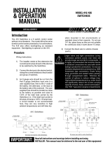
FWD
Parts List:
part no: Description: Qty:
1. T56186 L speaker bracket 1
2. T56187 Clamp bracket 1
3. T06139 Keps Nut 1/4-20 2
4. T14563 Carriage Bolt 1/4-20 2
5. T03440 Loop Strip 2
6. T03432 Hook Strip 2

4
Code 3
®
is a registered trademark of Code 3, Inc., a subsidiary of ecco inc.
PRODUCT RETURNS
If a product must be returned for repair or replacement*, please contact our factory to obtain a Return Goods Authorization Number
(RGA number) before you ship the product to Code 3, Inc. Write the RGA number clearly on the package near the mailing label. Be sure you
use sufcient packing materials to avoid damage to the product being returned while in transit.
*Code 3, Inc. reserves the right to repair or replace at its discretion. Code 3, Inc. assumes no responsibility or liability for expenses incurred for the removal and /or reinstallation of products requiring
service and/or repair.; nor for the packaging, handling, and shipping: nor for the handling of products return to sender after the service has been rendered.
PROBLEMS OR QUESTIONS? CALL OUR TECHNICAL ASSISTANCE HOTLINE (314) 996-2800
WWW.CODE3PSE.COM
Code 3®, Inc.
10986 N. Warson Road
St. Louis, Missouri 63114-2029—USA
Ph. (314) 426-2700 Fax (314) 426-1337
Part No. T56207 Rev. 0 05/2015©2005 Code 3, Inc
WARRANTY
Code 3,
®
Inc.'s emergency devices are tested and found to be operational at the time of manufacture. Provided they are installed and
operated in accordance with manufacturer's recommendations, Code 3, Inc. guarantees all parts and components except the lamps to a period
of 1 year (unless otherwise expressed) from the date of purchase or delivery, whichever is later. Units demonstrated to be defective within the
warranty period will be repaired or replaced at the factory service center at no cost.
Use of lamp or other electrical load of a wattage higher than installed or recommended by the factory, or use of inappropriate or inadequate
wiring or circuit protection causes this warranty to become void. Failure or destruction of the product resulting from abuse or unusual use and/or
accidents is not covered by this warranty. Code 3, Inc. shall in no way be liable for other damages including consequential, indirect or special
damages whether loss is due to negligence or breach of warranty.
CODE 3, INC. MAKES NO OTHER EXPRESS OR IMPLIED WARRANTY INCLUDING, WITHOUT LIMITATION, WARRANTIES OF
FITNESS OR MERCHANTABILITY, WITH RESPECT TO THIS PRODUCT.
Larger wires and tight connections will provide longer service life for components. For high current wires it is highly
recommended that terminal blocks or soldered connections be used with shrink tubing to protect the connections. Do
not use insulation displacement connectors (e.g. 3M
®
Scotchlock type connectors). Route wiring using grommets
and sealant when passing through compartment walls. Minimize the number of splices to reduce voltage drop. High
ambient temperatures (e.g. underhood) will signicantly reduce the current carrying capacity of wires, fuses, and circuit
breakers. Use "SXL" type wire in engine compartment. All wiring should conform to the minimum wire size and other
recommendations of the manufacturer and be protected from moving parts and hot surfaces. Looms, grommets,
cable ties, and similar installation hardware should be used to anchor and protect all wiring. Fuses or circuit breakers
should be located as close to the power takeoff points as possible and properly sized to protect the wiring and devices.
Particular attention should be paid to the location and method of making electrical connections and splices to protect
these points from corrosion and loss of conductivity. Ground terminations should only be made to substantial chassis
components, preferably directly to the vehicle battery. The user should install a fuse sized to approximately 125% of
the maximum Amp capacity in the supply line to protect against short circuits. For example, a 30 Amp fuse should
carry a maximum of 24 Amps. DO NOT USE 1/4" DIAMETER GLASS FUSES AS THEY ARE NOT SUITABLE FOR
CONTINUOUS DUTY IN SIZES ABOVE 15 AMPS. Circuit breakers are very sensitive to high temperatures and will
"false trip" when mounted in hot environments or operated close to their capacity.
WARNING!
/