Page is loading ...

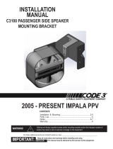
INSTALLATION
MANUAL
C3100 SPEAKER BRACKET
Read all instructions and warnings before installing and using.
This manual must be delivered to the end user of this equipment.
IMPORTANT:
Installation & Mounting.........................................................2
Parts List...........................................................3
Warranty................................................................................4
CONTENTS:
For future reference record your product's serial no. here __________________________________________
INSTALLER:
2011 CAPRICE PPV
Speaker Bracket installation in front of DS wheel well

2
Installation Instructions
PROCESS SEQUENCE:
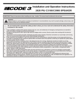
1. Remove (4) 7mm hex head screws across front lower edge of facia
2. Remove (8) Torx head screws -(4) ea. side / Pass & Driver sides, at fwd edges of front wheel wells (g 1)
3. Remove (2) hex head bolts behind fwd wheel well covers -(1) ea. side / Pass & Dirver sides (g 2)
4. Remove (4) Push-In plastic fasteners across front edge of top facia (g 3)
5. Set facia off of vehicle
(Note: wire harness at Passenger side will still be attached to vehicle, disconnect electrical connector if
desired)
6. Remove (2) 10mm hex head bolts from bumper crush cover -(1) ea. side at area under each headlight (g 4)
7. To expose bumper bolt access: Remove bumper crush cover:
a. Starting at one end of the bumper area- reach under crush zone cover along lower edge of bumper and pull
plastic clip tabs down while pulling the crush zone cover forward
b. Move across crush zone cover releasing the remaining 3 clip tabs while pulling forward on crush zone
cover until all (4) clip tabs are released and cover is removed from bumper (g 5)
8. Remove (2) Driver Side bumper retaining bolts from vehicle (g 6)
9. Install (2) longer retaining bolts provided from kit into Driver Side bumper- replacing the (2) removed in step 8
10. Assemble speaker onto mounting bracket using (4) round head phillips screws provided in kit making sure the
speaker is facing in the same direction as the forward facing mounting leg of the bracket and the Code 3 emboss is
upright when forward facing. (g 7)
11. Place bracket and speaker assembly into area forward of Driver Side front wheel well (g 8)
12. Position 2 holes in mounting bracket over top of newly installed bumper retaining bolts.
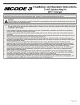
13. Install split lock washers and 8mm nuts over bumper bolts and tighten with socket until lock washers are fully
compressed (g 9 on pg 3)
14. Connect speaker wiring to harness as desired
15. Replace bumper crush zone cover by placing cover over bumper with retainint tabs along lower edge of bumper
by applying rm pressure until all (4) retaining tabs fully seat onto bumper assembly (g 10 on pg 3)
16. Replace (2) 10mm crush zone cover bolts at both Driver and Passenger side headlight assembly areas
Note: (while front facia is removed other equipment or wiring harnesses needed may be more easily installed at
this time)
17. Replace front facia on vehicle by working backwards through steps 4 to 1 in this process.
g 1
g 2
g 3
g 4
g 5
g 6
g 7
g 8

3
Utilizing non-factory supplied screws and/or mounting brackets and/or the improper
number of screws may result in loss of warranty coverage on the equipment.
WARNING!
Larger wires and tight connections will provide longer service life for components. For high current wires it
is highly recommended that terminal blocks or soldered connections be used with shrink tubing to protect
the connections. Do not use insulation displacement connectors (e.g. 3M
®
Scotchlock type connectors).
Route wiring using grommets and sealant when passing through compartment walls. Minimize the
number of splices to reduce voltage drop. High ambient temperatures (e.g. under hood) will signicantly
reduce the current carrying capacity of wires, fuses, and circuit breakers. Use "SXL" type wire in engine
compartment. All wiring should conform to the minimum wire size and other recommendations of the
manufacturer and be protected from moving parts and hot surfaces. Looms, grommets, cable ties, and
similar installation hardware should be used to anchor and protect all wiring. Fuses or circuit breakers
should be located as close to the power takeoff points as possible and properly sized to protect the wiring
and devices. Particular attention should be paid to the location and method of making electrical connections
and splices to protect these points from corrosion and loss of conductivity. Ground terminations should
only be made to substantial chassis components, preferably directly to the vehicle battery. The user should
install a fuse sized to approximately 125% of the maximum Amp capacity in the supply line to protect
against short circuits. For example, a 30 Amp fuse should carry a maximum of 24 Amps. DO NOT USE
1/4" DIAMETER GLASS FUSES AS THEY ARE NOT SUITABLE FOR CONTINUOUS DUTY IN SIZES
ABOVE 15 AMPS. Circuit breakers are very sensitive to high temperatures and will "false trip" when
mounted in hot environments or operated close to their capacity.
WARNING!
Part Description Qty: Part Number
Speaker Bracket 1 T56467
High Strength Hex Bolts 2 T56527
8mm nut 2 T57015
5/16 split washer 2 T00245
C3100 Speaker Assembly 1 S71684
PARTS LIST:
g 9
g 10
Completed installation prior to re-assembly of
front bumper cover and vehicle facia

4
WARRANTY
This product was tested and found to be operational at the time of manufacture. Provided this product
is installed and operated in accordance with the manufacturer's recommendations, CODE 3, Inc. guarantees
this product for a period of 5 years from the date of purchase or delivery, whichever is later (does not apply to
lamps). Units demonstrated to be defective within the warranty period will be repaired or replaced at the factory
service center at no cost.
Use of a lamp or other electrical load of a wattage higher than installed or recommended by the factory,
or use of inappropriate or inadequate wiring or circuit protection causes this warranty to become void. Failure
or destruction of the product resulting from abuse or unusual use and/or accidents is not covered by this war-
ranty. Use of non-CODE 3, Inc. components and assemblies may cause damage to the system and/or personal
injury, and voids all warranties.
CODE 3, Inc. shall in no way be liable for other damages including consequential, indirect or special
damages whether loss is due to negligence or breach of warranty.
CODE 3, INC. MAKES NO OTHER EXPRESS OR IMPLIED WARRANTY INCLUDING, WITHOUT LIMI-
TATION, WARRANTIES OF FITNESS OR MERCHANTABILITY, WITH RESPECT TO THIS PRODUCT.
Code 3 is a registered trademark of Code 3, Inc. a subsidiary of Public Safety Equipment, Inc.
Revision - 0, 05/2011 - Instruction Book Part No. T56533
©2011 CODE 3, Inc. Printed in USA
CODE 3, Inc.
10986 N. Warson Road
St. Louis, Missouri 63114-2029—USA
Ph. (314) 426-2700 Fax (314) 426-1337
www.code3pse.com
PRODUCT RETURNS
In order to provide you with faster service, if you are going to return a product for repair or replacement*,
please contact our factory to obtain a Return Goods Authorization Number (RGA number) before you ship the
product to Code 3. Write the RGA number clearly on the package near the mailing label. Be sure you use suf-
cient packing materials to avoid damage to the product being returned while in transit.
*Code 3, Inc. reserves the right to repair or replace product at its discretion and assumes no responsibility or liability for expenses
incurred for the removal and/or reinstallation of products requiring service and/or repair.
Problems or Questions? Call our Technical Assistance HOTLINE - (314) 966-2800
/