Page is loading ...


Revision History
1999 Rev
. B
Kodak DryView 8300 Laser Imager Customer First Service Manual
Revision History
The original issue and revisions of this manual are identified as follows:
Issue Date (Rev. A): 06/97, (Rev. B): 04/99
The conversion to Kodak content and format included in this revision has resulted in a complete reprint of
this existing Customer First Service Manual.
All pages are dated April, 1999.

W
arnings and Cautions
1999 Rev
. B
Kodak DryView 8300 Laser Imager Customer First Service Manual
i
Warnings and Cautions
Classifications
UL Classified
File Number E163816
Control Number 48VF
Medical Equipment
UL 2601-1 CAN/CSA No. 601.1
!
Classified by Underwriters Laboratories Inc. With Respect to Electric Shock, Fire, Casualty and
Medical Hazards only in Accordance with UL 2601-1, CAN/CSA C22.2 No. 601.1 and IEC 601.1.
Read and understand all instructions before using.
!
WARNING
This equipment can be an explosive hazard. Do not use in the presence of flammable
anesthetics, Oxygen, or Nitrous Oxide.
!
WARNING
This equipment is operated with hazardous voltage which can shock, burn, or cause
death.
Remove wall plug before servicing equipment. Never pull on cord to remove from outlet. Grasp plug and
pull to disconnect.
Do not operate equipment with a damaged power cord.
Do not use an extension cord to power this equipment.
Position the power cord so it will not be tripped over or pulled.
Connect this equipment to a grounded outlet.
!
WARNING
Not Protected Against Ingress of Liquids, including bodily fluids.
!
WARNING
For Continued Protection against Fire, Replace Fuses with only the Same Type and Fuse Rating.

Warnings
and Cautions
1999 Rev
. B
Kodak DryView 8300 Laser Imager Customer First Service Manual
ii
Warnings and Cautions (Continued)
Avoid touching the developer roll when removing film jams from the imager. The developer roll may
become hot during extended imager operation.
!
CAUTION
This equipment generates, uses, and can radiate radio frequency energy, and if not installed by qualified
service personnel and used in accordance with the User Guide, may cause interference to radio
communications and other electronic devices. Operation of this equipment in a residential area may
cause interference, in which case the user, at his or her own expense, will be required to take whatever
measures may be required to correct the interference.
!
CAUTION
This equipment is intended to connect to other medical devices. Installation and service maintenance are
to be performed only by qualified service personnel.
!
CAUTION
General External Cleaning: This equipment may be cleaned with a damp cloth using water with mild
detergent, or commercial electronic equipment cleaner.

Warnings
and Cautions
1999 Rev
. B
Kodak DryView 8300 Laser Imager Customer First Service Manual
iii
Warnings and Cautions (Continued)
!
CAUTION
Avoid Laser Beam
This equipment employs an invisible 25 milliwatt laser beam. Laser radiation may be
present when the machine operates without panels or covers installed.
Use of controls or adjustments, or performance of procedures other than those specified herein, may
result in eye damage.
Covers shall be removed by authorized service personnel only.
There are no “user” serviceable parts in this machine other than the charcoal odor filter.
Type B Applied Part

Agency
, Regulatory and CE Marking Compliance
1999 Rev
. B
Kodak DryView 8300 Laser Imager Customer First Service Manual
iv
Agency, Regulatory and CE Marking Compliance
All agency, regulatory and CE marking compliance information may be found in the user’s guide for this
model.

Section 1 – Introduction/Specifications
1999 Rev
. B
Kodak DryView 8300 Laser Imager Customer First Service Manual
1-1
Section 1 – Introduction/Specifications
1-1. Introduction
1-1-1. Purpose of this Manual
This manual is designed for trained in-service personnel who are responsible for “Customer-First” service
of the DryView 8300 Laser Imager. The Customer-First level of service includes basic machine problem
analysis and repair, as well as periodic preventive maintenance.
Special training is required to perform the service tasks described in this manual. Service attempts by
untrained personnel that result in damage to the system are the responsibility of the user. Training can be
provided at the user site by an experienced technician.
Note
For help with any machine problem not covered in this manual, the service technician should call for
service.
1-1-2. Introducing the DryView 8300 Laser Imager
The DryView 8300 Laser Imager is a continuous tone laser imager with an integrated
photothermographic film developer. The imager uses 8 by 10 inch (20.3 by 25.4 cm) DryView Laser
Imaging Film, which is packaged in 100-sheet cartons.
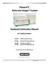
1-1-3. How the DryView 8300 Laser Imager Works
The following sequence occurs each time the imager receives a print command. The circled numbers in
Figure 1-1 correspond with the numbered steps below. The dashed lines in the illustration indicate the film
path.
1. Film Feed– A sheet of film is driven from the supply tray and into separation rollers.
2. Film Separation– Rollers check for more than one sheet of film, then drive a single sheet into the
exposure module.
3. Film Exposure– A laser beam exposes the sheet of film, and the sheet is guided into the film
developer.
4. Film Development– The film develops as it passes over a heated drum.
5. Image Quality Check– The film is driven out of the film developer, through the densitometer, and out to
the receive tray. The densitometer is a key element in the Automatic Quality Control process. It allows
the imager to automatically adjust image processing parameters to ensure optimum image quality. The
imager adjusts parameters each time it prints a calibration sample. Calibration samples are printed
whenever:
The imager is powered on.
The film tray is inserted in the imager.
The user requests a sample from the Setup Menu.
A calibration sheet has not been printed for 24 hours.
The imager wakes up from energy saver mode.

Section
1 – Introduction/Specifications
1999 Rev
. B
Kodak DryView 8300 Laser Imager Customer First Service Manual
1-2
2 1
3
4
5
8300–179L
Figure 1-1. Print Sequence
1-2. Specifications
1-2-1. Dimensions
Height: 46 cm (18 in.)
Width: 46 cm (18 in.)
Depth: 66 cm (26 in.)
Weight: 56 Kg (124 lbs)
1-2-2. Electrical
Voltage: 100 to 240 VAC " 10%, 50/60 Hz " 3%
Current Required: 6.3/3.2 Amperes
1-2-3. Operating Environment
Temperature: 15° to 32°C (59° to 90°F)
Humidity: 15% to 75% RH, Noncondensing
Magnetic Field: v 100 Gauss
1-2-4. Interface Modules
Standard Resolution Analog
Standard Digital
SCSI
Network

Section
1 – Introduction/Specifications
1999 Rev
. B
Kodak DryView 8300 Laser Imager Customer First Service Manual
1-3
1-2-5. Control Interfaces
Control panel
Remote keypad
Host
1-2-6. Output Rate
First print: 110 seconds (after Ready indicator lights)
Subsequent prints: 55 prints per hour
1-2-7. Film Characteristics
Size: 8 by 10 inches
Film tray capacity: 100 sheets
1-2-8. Options
Second input module
Internal magneto/optical drive

Section 2 – Preventive Maintenance
1999 Rev. B
Kodak DryView 8300 Laser Imager Customer First Service Manual
2-1
Section 2 – Preventative Maintenance
2-1. The Value of Preventive Maintenance (PM)
In order to consistently produce the highest quality images, the 8300 must receive periodic routine
maintenance. The Customer First technician is required to perform preventive maintenance procedures at
the intervals shown in the checklists in paragraph 2-5.
2-2. Supplies Required for PM
1. Isopropyl alcohol, 99% (1 quart) 78-8033-7475-6
2. Zip lock bags (1 quart size)
3. Insulated rubber gloves
4. Cleaning pads, lint–free (1 bag) 78-8018-2802-7
5. 3M TroubleshooterCleaner 96-0000-0066-9
6. Pre-soaked alcohol pads 78-8005-4980-6
Note
Items 1 through 4 above can be purchased locally. If a brand name is indicated, the supply must be
bought under this name. If no brand name is listed, the specification in the description must be
observed.
2-3. Replacement Parts Required for PM
To obtain parts, call your local technician.
2-4. Tools Required for PM
0.004 inch and 0.006 inch feeler gauges
5/16 inch open end wrench
3/32 inch ball head driver
Phillips screwdriver with No. 2 tip
Standard tip screwdriver

Section 2 – Preventive Maintenance
1999 Rev. B
Kodak DryView 8300 Laser Imager Customer First Service Manual
2-2
2-5. PM Checklists
The following paragraphs 2-5-1 through 2-5-6 provide a series of checklists for PM procedures that are to
be performed at successive 10,000 machine cycle intervals. The procedures to be performed at the various
intervals are summarized in Table 2-1.
Table 2-1.
Procedures
(Perform in order where indicated
by x in column.)
Every
10,000
Cycles
Every
20,000
Cycles
Every
30,000
Cycles
Every
40,000
Cycles
Every
50,000
Cycles
Every
60,000
Cycles
2-6. Disassemble Processor.
2-7. Clean Processor:
1. Drum
2. Pressure Roller Assys (2)
3. Ultem Film Guide
4. Entrance and Exit Rollers
5. Stripper
x
x
x
x
x
x
x
x
x
x
x
x
x
x
x
x
x
x
x
x
x
x
x
x
x
x
x
x
x
x
x
x
x
x
x
x
2-8. Replace Felt Pad Assy. x x x x x x
2-9. Clean Densitometer. x x x x x x
2-10. Clean Capstan Rollers. x x
2-11. Clean Separator O-Rings. x x
2-12. Clean Film Feed Roller. x x
2-13. Reassemble Processor. x x x x x x
2-14. Check Stripper Gap. x x x x x x
2-15. Clean/replace Filters:
1. Clean Fan Filter.
2. Replace Charcoal Filter.
3. Replace Faz Filter.
x x
x
x x
x
x x
x
x
2-16. Print a film cal sheet and
confirm quality.
x x x x x x
Note
PM at 70,000 cycles is the same as at 10,000 cycles, and PM at 80,000 cycles is the same as at
20,000 cycles, etc.

Section 2 – Preventive Maintenance
1999 Rev. B
Kodak DryView 8300 Laser Imager Customer First Service Manual
2-3
2-5-1. 10,000 Cycle PM Checklist
Every 10,000 machine cycles:
- 1. Disassemble the Processor. (See paragraph 2-6.)
- 2. Clean the Drum. (See paragraph 2-7-1.)
- 3. Clean the Upper and Lower Pressure Roller Assemblies. (See paragraph 2-7-2.)
- 4. Clean the Ultem Film Guide. (See paragraph 2-7-3.)
- 5. Clean the Processor Entrance and Exit Rollers. (See paragraph 2-7-4.)
- 6. Clean the Stripper. (See paragraph 2-7-5.)
- 7. Replace the Felt Pad Assembly. (See paragraph 2-8.)
- 8. Clean the Densitometer. (See paragraph 2-9.)
Note
After completing cleaning, place the used cleaning pads in a zip lock bag and dispose of them
properly.
- 1. Reassemble the Processor components. (See paragraph 2-13.)
- 2. Check the Stripper gap, and readjust as necessary. (See paragraph 2-14.)
- 3. Clean the Fan Filter. (See paragraph 2-15-1.)
- 4. Print a film calibration from the local panel and confirm image quality (See paragraph 2-16.)
- 5. After completing the PM procedures, record the date and machine cycle count on a log sheet.
2-5-2. 20,000 Cycle PM Checklist
- 1. Perform all the procedures of 10,000 Cycle PM maintenance. In addition:
- 2. Replace the Charcoal Filter. (See paragraph 2-15-2.)
2-5-3. 30,000 Cycle PM Checklist
- 1. Perform all the procedures of 10,000 Cycle PM maintenance. In addition:
- 2. Clean the Capstan Rollers. (See paragraph 2-10.)
- 3. Clean the Separator O-Rings. (See paragraph 2-11.)
- 4. Clean the Film Feed Roller. (See paragraph 2-12.)

Section 2 – Preventive Maintenance
1999 Rev. B
Kodak DryView 8300 Laser Imager Customer First Service Manual
2-4
2-5-4. 40,000 Cycle PM Checklist
- 1. Perform all the procedures of 10,000 Cycle PM maintenance. In addition:
- 2. Replace the Charcoal Filter. (See paragraph 2-15-2.)
2-5-5. 50,000 Cycle PM Checklist
- 1. Perform the procedures of 10,000 Cycle PM maintenance.
2-5-6. 60,000 Cycle PM Checklist
- 1. Perform all the procedures of 30,000 Cycle PM maintenance. In addition:
- 2. Replace the Charcoal Filter. (See paragraph 2-15-2.)
- 3. Replace the Faz Filter. (See paragraph 2-15-3.)
2-6. Disassembling the Processor
Disassemble the processor to prepare for cleaning in the order indicated in the following paragraphs. After
disassembly, a waste container, preferably a sink, will be required to clean the processor drum and rollers.
If a sink is not available, a leakproof container large enough to hold the drum and rollers can be used.
Note
Be aware that the processor cleaning procedure produces fumes that may be objectionable to those nearby. Try
to find a cleaning area where complaints will be minimized.
Tools Required for Disassembly
Phillips screwdriver
Standard tip screwdriver

Section 2 – Preventive Maintenance
1999 Rev. B
Kodak DryView 8300 Laser Imager Customer First Service Manual
2-5
2-6-1. Remove the Left and Right Side Covers
1. Power down and unplug the power cord.
!
Warning
When the power cord is plugged in, hazardous voltages are present in some areas of the DryView
8300. These voltages can cause severe injury or death.
2. Remove the film tray.
3. Raise the top cover.
4. Remove three attaching screws from each side cover (see Figure 2-1).
5. Grasp each cover by the bottom and pull out to remove it.
Figure 2-1. Removing the Side Covers

Section 2 – Preventive Maintenance
1999 Rev. B
Kodak DryView 8300 Laser Imager Customer First Service Manual
2-6
2-6-2. Remove the Processor Assembly
1. With power removed and the power cord disconnected, allow the processor to cool down.
2. Disconnect the plugs from P2, P3, and P4 on the CPU PWA (see View A of Figure 2-2).
3. Disconnect the plug from P5 of the power module.
4. Remove two attaching screws from each side of the processor base (see View B of Figure 2-2).
5. Remove the processor assembly from the machine.
Figure 2-2. Removing the Processor Assembly

Section 2 – Preventive Maintenance
1999 Rev. B
Kodak DryView 8300 Laser Imager Customer First Service Manual
2-7
2-6-3. Remove the Processor Half from the Processor
1. Unlatch the processor cover.
2. Remove one attaching screw from each side (see Figure 2-3).
3. Remove the processor half.
Figure 2-3. Removing the Processor Half

Section 2 – Preventive Maintenance
1999 Rev. B
Kodak DryView 8300 Laser Imager Customer First Service Manual
2-8
2-6-4. Remove the Drum
1. Disconnect the ground wire from the right side of the processor assembly (see Figure 2-4).
2. Remove a locking plate from each side of the drum.
3. Manually turn the bearing blocks to align the flats for removal of the drum (see inset in Figure 2-4).
4. Lift the drum from the processor and carefully lay it down (until cleaning in paragraph 2-7).
Figure 2-4. Removing the Drum

Section 2 – Preventive Maintenance
1999 Rev. B
Kodak DryView 8300 Laser Imager Customer First Service Manual
2-9
2-6-5. Remove the Upper Pressure Roller Assembly
1. Remove the two latches from the processor cover (see Figure 2-5).
2. Remove the screw retaining clip from the lower shaft on the left side of the cover.
3. On the right side of the cover, remove the screws (one each shaft) from the ends of the two shafts
securing the pressure rollers.
4. Pull the shafts out from the left side.
5. Remove the upper pressure roller assembly and place it in the sink (or other container) for cleaning.
Figure 2-5. Removing the Upper Pressure Roller Assembly

Section 2 – Preventive Maintenance
1999 Rev. B
Kodak DryView 8300 Laser Imager Customer First Service Manual
2-10
2-6-6. Remove the Lower Pressure Roller Assembly
1. Remove the retaining clip from the lower shaft on the right side of the processor housing (see
Figure 2-6) .
2. On the left side of the housing, remove the screws from the two shafts securing the lower roller
assembly.
3. Pull the two shafts out from the right side.
4. Remove the lower pressure roller assembly and place it in the sink (or other container) for cleaning.
Figure 2-6. Removing the Lower Pressure Roller Assembly

Section 2 – Preventive Maintenance
1999 Rev. B
Kodak DryView 8300 Laser Imager Customer First Service Manual
2-11
2-7. Cleaning the Processor
Clean the processor components in the order specified in the following paragraphs.
!
Caution
The processor cleaning procedure produces fumes that may be objectionable to those nearby. Try to
find a cleaning area where complaints will be minimized.
2-7-1. Clean the Drum (10,000 Cycles)
Supplies Required
3M Troubleshooter Cleaner
Isopropyl alcohol
Cleaning pads
Protective gloves
Procedure
Note
The drum (and rollers, in the next procedure) must be cool to the touch before you apply
Troubleshooter cleaner to them. Wear protective gloves while cleaning.
1. Hold the drum upright in a sink (or other leakproof container) with the plastic gear down while cleaning.
Be careful with the delicate electronic components on the top of the drum.
!
Caution
While you spray the drum with Troubleshooter, make sure that the spray does not contact the wires
and electronics on the top end (opposite the plastic gear).
2. While holding the drum by the top with one hand, slowly spray Troubleshooter onto the surface while
you rotate the drum. Make sure you spray the entire surface of the drum that contacts film.
3. Allow the Troubleshooter to remain on the drum for about 5 minutes. Then slowly and carefully wipe the
spray from the drum with cleaning pads.
4. Repeat steps 2 and 3.
5. Wipe the drum with alcohol and cleaning pads to remove any remaining Troubleshooter.
6. Wipe the drum with cleaning pads until it is clean and dry.
7. Carefully lay the drum aside until reassembly.
/