Page is loading ...

Model GS-800
Calibrated Imaging
Densitometer
User's Guide
For Catalog Numbers
170-7980 GS-800 Densitometer, PC
170-7981 GS-800 Densitometer, Mac
For Technical Service
Call Your Local Bio-Rad Office or
In the U.S. Call 1-800-4BIORAD
(1-800-424-6723)
WWW.BIO-RAD.COM
4000188 Rev. A Copyright 2002 Bio-Rad Laboratories Inc.


2
Warranty Statement
Bio-Rad Model GS-800 Calibrated Imaging Densitometer
This warranty may vary outside of the United States. Please contact your local Bio-Rad
office for the exact terms of your warranty.
Bio-Rad Laboratories warrants to the customer that the Model GS-800 Calibrated Imaging
Densitometer (Catalog Number 170-7980 or 170-7981) will be free from defects in material
and workmanship, and will meet all performance specifications for the period of one year
from the date of shipment. This warranty covers all parts and labor.
In the event that the instrument must be returned for repair under warranty, the
instrument must be packed for return in the original packaging.
Bio-Rad shall not be liable for any incidental, special or consequential loss, damage, or
expense directly or indirectly arising from the use of the Model GS-800 Calibrated Imaging
Densitometer. Bio-Rad makes no warranty whatsoever in regard to products or parts
furnished by third parties, such being subject to the warranty of their respective
manufacturers. Service under this warranty shall be requested by contacting the
customer’s nearest Bio-Rad office.
This warranty does not extend to any instruments or parts thereof that have been subject
to misuse, neglect or accident, or that have been modified by anyone other than Bio-Rad or
Bio-Rad's authorized agent, or that have been used in violation of Bio-Rad instructions.
For any inquiry or request for repair service, contact Bio-Rad Laboratories. Inform Bio-
Rad of the model and serial number of your instrument.

3

4
Table of Contents
Section 1 General Information .......................................................................................................6
1.1 Introduction............................................................................................................................6
1.2 Installation Qualification and Operational Qualification( IQ/OQ )......………………..6
1.3 Safety…………………………....................................…………………………………...…..7
1.4 Regulatory Compliance ........................................................................................................7
Section 2 Setting Up.........................................................................................................................8
2.1 Checking the Contents..........................................................................................................8
2.2 Unpacking the Contents .......................................................................................................8
2.3 Unlocking the Densitometer and the Transparency Module..........................................9
2.4 Locking the Densitometer and the Transparency Module............................................10
2.5 Taking a Closer Look...........................................................................................................10
Section 3 Installation......................................................................................................................12
3.1 About SCSI Devices.............................................................................................................12
3.2 Changing the SCSI ID Number..........................................................................................12
3.3 Checking the Terminators..................................................................................................13
3.4 Installation for the Macintosh or PC Computer.............................................………….14
3.5 Testing the Densitometer....................................................................................................15
Section 4 Operation........................................................................................................................16
4.1 Overview of Operational Components ............................................................................16
4.2 Start-Up.................................................................................................................................18
4.3 Reflective Scanning..............................................................................................................18
4.4 Transmittance Scanning......................................................................................................18
Section 5 Maintenance...................................................................................................................20
5.1 Cleaning the Image Window Glass...................................................................................20
5.2 Cleaning the Cabinet Exterior............................................................................................20
Section 6 Troubleshooting ............................................................................................................21
6.1 Troubleshooting...................................................................................................................21
6.2 Technical Service..................................................................................................................23
Section 7 Technical Specifications................................................................................................24

5

6
Section 1 General Information
1.1 Introduction
The Model GS-800 Calibrated Imaging Densitometer is a high performance, calibrated
imaging densitometer that converts transparent and opaque electrophoretic samples into
digital data. These data are analyzed with Quantity One® software operating in either
Microsoft Windows
®
or Macintosh
®
computer systems. For a step-by-step guide to
scanning and analyzing images, please refer to your Quantity One software user manual.
The main features of the Model GS-800 Calibrated Imaging Densitometer include:
• Adjustable resolution from 36.3 microns to 127.0 microns;
• Reflectance and transmittance
• Scanning area of 29 cm by 40 cm
• Sampling rate of up to 700 dots per inch (dpi).
• Stationary platen for higher reliability
• Variable wavelength lamp/filter architecture for improved color discrimination
• Analog to digital conversion at full 12-bit accuracy
• Calibrated transmission tablet to ensure accurate OD readings
• Reflective gray scale tablet to ensure reproducible reflectance values
• Supported by Quantity One software, which provides versatile image display,
optimization, and quantitation features
1.2 Installation Qualification and Operational Qualification ( IQ/OQ )
The calibration of the Model GS-800 Calibrated Imaging Densitometer can be validated by
following the GS-800 Calibrated Densitometer Installation Qualification and Operational
Qualification protocols. These protocols are available as an accessory to the GS-800
Calibrated Imaging Densitometer ( Catalog number 170-7956 ). These straightforward and
simple to follow IQ/OQ protocols include instructions for the installation of the hardware
and software, and instructions for the verification of the reflectance and transmittance
calibration functions.
Following proper installation, a linear dynamic range of 3.0 OD for the
Transmissive scanning and 2.0 OD for Reflectance scanning can be confirmed with
greater than 95% confidence. For additional details, contact your local Bio-Rad
Representative.

7
1.3 Safety
The Model GS-800 Calibrated Imaging Densitometer system uses high voltage and high
current and should be operated with care at all times. To avoid shock, set up the GS-800
Densitometer in a dry area. Immediately wipe up any spilled solutions.
• Turn off the Densitometer, and then disconnect the power plug when you want to
clean the Densitometer case or glass plate, or when the Densitometer needs service or
repair.
• Place the Densitometer on a level surface.
• To ensure proper ventilation, allow a minimum of 15 cm free space around each side of
the Densitometer.
• Do not leave photographs, gels, or film on the glass plate for excessive periods of time.
The heat from the light source in the Densitometer may cause them to deteriorate.
• Do not operate the Densitometer when the environmental temperature falls below 5° C
or rises above 40° C.
• Do not operate the Densitometer when the environmental humidity falls below 25% or
rises above 85%.
1.4 Regulatory Compliance*
Declaration of Compliance
The party responsible for product compliance
Corporate Name: UMAX Technologies, Inc.
Address: 3561 Gateway Blvd. Fremont, CA 94538, U.S.A.
Telephone No.: 510-651-4000
*See UMAX PowerLook 2100XL Operation Manual

8
Section 2 Setting Up
2.1 Checking the Contents
Your Model GS-800 Calibrated Imaging Densitometer system should arrive complete with
one of each of the following:
• GS-800 Calibrated Imaging Densitometer
• GS-800 Calibrated Imaging Densitometer User Guide
• Quantity One™ Image Analysis Software
• UMAX PowerLook 2100XL Operation Manual
• 25/50-pin SCSI Cable
• Power Cord
• Photoperfect and Adobe Photoshop LE
• MagicScan CD and manual
These components may arrive in several boxes. If your system is missing any of these
items, immediately contact your local Bio-Rad office for a prompt replacement. Please
retain all packaging material. Additional charges will be assessed if packaging is not
available for instrument warranty service shipping.
Caution: Use care when unpacking your equipment. The equipment is delicate and
damage can occur if it is dropped or otherwise mistreated.
2.2 Unpacking the Contents
Unpacking the Model GS-800 Calibrated Imaging Densitometer shipping container:
Warning: The Model GS-800 Calibrated Imaging Densitometer weighs approximately 45.8
lbs. (20.8 kg). To avoid personal injury, two people may be needed to lift the Densitometer
out of the shipping container. Lifting the unit just by the lid may cause damage to the
instrument
1. Carefully lift the Model GS-800 Calibrated Imaging Densitometer out of the shipping
carton and place it on a stable, dry, flat surface. The chassis of the Model GS-800
Calibrated Imaging Densitometer attempts to conform to any uneven surface. This
may result in a poor-quality scan.
2. Remove the plastic wrapping and the packing materials from the Densitometer.
3. The Model GS-800 Calibrated Imaging Densitometer should be located close to the
computer system to which it will be connected. Select a flat, dry surface that
provides adequate ventilation on all sides to prevent overheating.

9
4. The Model GS-800 Calibrated Imaging Densitometer can operate with 100V AC to
264V AC. Check the power cord to insure that it is suitable for your area.
Caution: The power cord plug provided has a third grounding pin. This plug fits in a
grounding-type outlet only. This is a safety feature. If you are unable to plug the power
cord into a wall outlet, locate another outlet that can accommodate the plug or contact
your electrician to change the outlet. Do not change the plug.
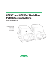
2.3 Unlocking the Densitometer and the Transparency Module
The optical assembly of the Densitometer’s transparency module (located in the lid) is held
in place during shipment by a carriage lock (Figure 2.1) on the underside of the
transparency module. The carriage lock must be unlocked before the instrument will
work properly. Additionally, if the carriage lock is not unlocked prior to use, the optical
system may be damaged while scanning. Insert a coin into the Carriage Lock. Turn it
until the mark points align with the unlocked mark.
Note: Leave the locking screw in place so that it can be re-locked if you have to move the
Densitometer over long distances.
Fig. 2.1 Front view of Densitometer. Unlock the carriage lock by turning with a coin.
Warning: Always lower the transparency module slowly and release it only when it lies
flat on the body of the Densitometer.
Carriage
Lock

10
2.4 Locking the Densitometer and the Transparency Module
To transport or ship the Densitometer, be sure to re-lock the optical assembly to avoid
damage to it. Before re-locking the assembly, make sure the optical assembly of the
transparency adapter is in the Home Position by doing the following:
1. If the Densitometer is powered on, turn the Densitometer off.
2. Turn the Densitometer’s power back on.
3. Wait for the Densitometer’s Ready and Power indicators to light up.
4. Turn the Densitometer off again. The transparency assembly should be in the
Home position.
To lock the optical assembly, insert a coin in the Carriage Lock. Turn it until the marked
points align with the locked marks.
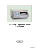
2.5 Taking a Closer Look
Now that you have the Model GS-800 Calibrated Imaging Densitometer out of the box,
take a closer look to familiarize yourself with the parts. Figures 2.2 and 2.3 illustrate the
locations of the different parts of your Model GS-800 Calibrated Imaging Densitometer.
Calibration
window
Bezel
Image
Window
Transparency
Module
Power
Switch
Power Indicator
Ready Indicator
Fig. 2.2 The front of Model GS-800 Calibrated Imaging Densitometer.

11
50-pin
SCSI
connector
25-pin
SCSI
connector
SCSI
Termination
Switch
SCSI ID
Switch
Power Cord
Connector
Fig. 2.3 The back of the Model GS-800 Calibrated Imaging Densitometer.

12
Section 3 Installation
3.1 About SCSI Devices
The Model GS-800 Calibrated Imaging Densitometer is a Small Computer System Interface
(SCSI) device. It communicates with your computer by using the SCSI-2 standard. The
SCSI communication standard allows you to connect more than one peripheral device to
the same port of your computer in chain fashion.
A unique SCSI ID number is assigned to each device in the SCSI chain enabling your
computer to identify the device with which it is communicating and the priority of each
device.
Warning: If two SCSI devices have the same ID number, your system will not work
properly and you may damage your SCSI devices.
A SCSI chain requires an electronic component called a 'terminator' which absorbs old
signals traveling along the cables and keeps the path open for new signals. The chain
should never have more than two terminators, one at each end. It is important to
remember that using too many or too few terminators may damage your SCSI devices.
Some SCSI devices have built-in terminators and must therefore be placed at the beginning
or end of your SCSI chain.
Note: The Model GS-800 Calibrated Imaging Densitometer has a built-in terminator.
3.2 Changing the SCSI ID Number
Your Densitometer's SCSI ID setting is factory preset at #6. Check to see if this ID setting
is used by another device connected to your computer’s SCSI port.
If SCSI ID #6 is not used, you do not need to change your Densitometer’s SCSI ID number.
You can directly proceed to hardware connection and software installation. For
installation instructions, proceed to Section 3.4 if you are connecting to a Macintosh
computer or to Section 3.5 if you are connecting to a PC.
If you find however, that another connected device is already using SCSI ID #6, then you
must reset the SCSI ID on your Densitometer.
To reset the SCSI ID, do the following:
1. Make sure the Densitometer power is off.
2. Use a screwdriver to rotate the notch on the SCSI ID switch until an arrowhead
points to an unused number.
Note: Do not use SCSI ID setting 7 through 9 on your Densitometer. They are for factory
use only.

13
3.3 Checking the Terminators
There should be two terminators in a SCSI chain. It is best to place the terminators at each
end of the SCSI chain. The GS-800 Calibrated Densitometer has a built-in active terminator
switch for you to turn on and off. Number 1 represents active terminator and number 2
represents terminator power. Turning both the active terminator and terminator power
switch on by pressing them down will enable the built-in “active terminator” function.
The simplest configurations for using the Densitometer with a SCSI adapter card are as
follows:
Case 1: Connect the Densitometer to an interface card that does not have another
SCSI device attached to it. e. g. Densitometer is the only SCSI device
connected to your computer.
In this situation, the card will have a built-in terminator. The card forms one end of the SCSI
chain, the Densitometer forms the other end. Turn on the active terminator and
terminator power switch by pressing them down to enable the built-in “active terminator”
function.
Case 2 : Connect the Densitometer to a SCSI card that has another SCSI device
attached to it.
In this case, turn off the active terminator on your Densitometer. If the SCSI device next
to Densitometer is the last SCSI device of the SCSI chain, please refer to the instruction
manual of this device to set its terminator on. If you experience unreliable SCSI operation
and suspect terminator problems, contact Bio-Rad Technical Service.
Case 3 : Densitometer is the last SCSI device in the SCSI Chain
The setting of active terminator is the same with Case 1. Simply turning on the active
terminator of your Densitometer.

14
3.4 Installation for the Macintosh or PC Computer
This section describes setting up the Model GS-800 Calibrated Imaging Densitometer with
your Macintosh or PC computer. You must first choose and set a SCSI ID number
(Section 3.2), then connect the Densitometer to your computer, and lastly test the
connection.
SCSI Adapter Card
The Model GS-800 Calibrated Imaging Densitometer requires a SCSI adapter card to work
with your computer. The Densitometer driver software supplied with the Densitometer
supports most Adaptec adapter cards.
Please check the following documentation:
• The Read Me file on the Quantity One software disk for up-to-date information.
• The documentation supplied with your Adaptec SCSI adapter card for instructions on
card installation.
SCSI Adapter Card Installation
Before you can use your Densitometer with your computer, you need to install the
interface card into your computer. Contact your local Bio-Rad Sales Representative or
Technical Service for the recommended Adaptec SCSI adapter. To install the card into one
of the computer's expansion slots, observe the following procedures:
Note: The interface card is sensitive to static electricity. Handle the card by its mounting
bracket, particularly when removing the card from its anti-static packaging.
1. Turn the computer power off and unplug the power cord.
2. Remove the housing cover of the computer. Follow the instructions provided in
your computer’s reference manual.
3. Remove the metal cover corresponding to your chosen slot. Keep the removed
screw so that it can be used to fasten the interface card.
4. Gently insert the interface card into the slot until it is firmly seated in the slot.
5. Secure the card in place with the screw removed from the expansion slot cover in
step 3 above.
6. Replace the housing cover following the instructions provided in the computer’s
reference manual.

15
Connect the Densitometer to the Computer
With settings on the Densitometer and card correctly set and the interface card properly
installed in your computer, you can now connect the Densitometer and the computer, as
follows:
1. Ensure that the Densitometer’s SCSI ID is properly set. Determine which SCSI ID
numbers are already assigned and which numbers are free. Refer to “Changing the
SCSI ID Number” in Section 3.2 for instructions on setting the Densitometer’s SCSI ID.
2. Turn on Active terminator and termination power (please refer to Section 3.3 for more
details on setting termination), connect the SCSI cable to SCSI port and connect the
other end of the SCSI cable to the Densitometer.
3. Connect the power cord to the Densitometer.
4. Turn on the Densitometer power.
5. Turn on the computer power.
3.5 Testing the Densitometer
Prepare your Densitometer for installation through the following steps:
1. Check and reset (if necessary) the Densitometer’s SCSI ID
2. Run the automatic Densitometer self-test (see below)
Test the Densitometer
The Densitometer automatically performs a simple self-test each time it is turned on. The
self-test checks the status of certain Densitometer devices.
Start the Densitometer self-test by following the steps below:
1. Connect the power cord to the Densitometer.
2. Connect the other end of the power cord to a wall outlet.
3. Turn on the power of the Densitometer. The on/off control is a push-button
switch located on the left front of the unit.
At power-on, the front panel indicators flash once. The power indicator then glows and
the ready indicator blinks. When the test is completed, the power and the ready indicators
glow steadily.
The Densitometer performs a self-test for approximately 35 seconds after which the
Densitometer indicator stabilizes. The Transparency Module indicator and the scanning
lamp stay on. If a problem occurs during the self-test, refer to Section 6, Troubleshooting.

16
Section 4 Operation
4.1 Overview of Operational Components
This chapter provides a summary of the Model GS-800 Calibrated Imaging Densitometer
components used during operation and explains the startup procedure.
Transparency Module
The Transparency Module (Figure 2.2) is secured to the Model GS-800 Calibrated Imaging
Densitometer by two elongated hinges at the rear of the Densitometer. This Transparency
Module should be lowered onto the Densitometer base for reflectance and transmittance
scanning. The thick border gasket on the transparency module allows you to place
samples up to 3.0 mm thick on the image window for scanning.
Warning: Always lower the transparency module slowly and release it only when it lies
flat on the body of the Densitometer.
Image Window
The image window (Figure 4.2) is the area where the sample to be scanned is positioned.
Light collected from the sample is focused through a lens onto a charge coupled device
(CCD) array that captures the image.
Caution: The image window is glass. To avoid breakage, do not press firmly or place
anything other than a sample for scanning on the image window.
Calibration Window
Both calibration
windows must be
kept clean for
proper operation.
Calibration Window
Bezel
Image
Window
Front
.
Figure 4.2 The image window and bezel on the Densitometer

17
Calibration Tablet Areas/Calibration Windows
The GS-800 Densitometer is equipped with reflectance and transmission step wedges.
The transmission step wedge is located on the left hand side of the image window. The
reflectance step wedge is internal. When you scan a transparent sample, place the sample
on the Densitometer's image window Do not cover the calibration windows (Figure 4.2) or
a calibration error will occur.
Validation and Documentation the calibration performance can be accomplished by the
following GS-800 IQ/OQ Protocols.
See section 1.2
Bezel
The bezel (Figure 4.2) is the raised frame around the image window. It has marks in
inches and centimeters to help you correctly position the sample on the image window for
scanning.
Indicator Lights
The indicator lights (Figure 2.2) are located on the front left side of the Model GS-800
Calibrated Imaging Densitometer cabinet. This panel consists of two lights that indicate
the status of the unit.
Light Description
Power Indicator Is lit when the power switch is in the on position (green light).
Ready Indicator Flashes during self-test(start-up) and during scans (green light).
Calibration Strip Values
The OD values of the built in Calibration Strip can be found either on the decal posted on
the side of the GS-800 (see below) or on the enclosed OD value sheet .
OD Values and Serial number of
the tranparency calibration tablet
are on this decal pasted to the
right side of the GS-800.
4.2 Start-Up

18
4.2 Start-Up
Turn on the Densitometer. The on/off control is a push-button switch located on the left
front of the unit. The Power indicator lights up. The Densitometer performs a self-test
that lasts approximately 35 seconds during which the Ready indicator flashes briefly. The
scanning lamp turns on and both indicator lights will stay on once the Densitometer is
powered up.
For optimum performance, allow the Densitometer to warm up for five minutes after
power-up.
The Model GS-800 Calibrated Imaging Densitometer is now ready for use.
4.3 Reflective Scanning
To scan a reflective sample:
1. Raise the Transparency Module.
2. Place the sample to be scanned facedown on the image window.
3. Guide the top corner of the sample to the lower left ( 0,29 ) corner of the image window.
4. Lower the Transparency Module
Warning: Always lower the transparency module slowly and release it only when it lies
flat on the body of the Densitometer.
5. For more information about scanning operations and options, refer to the Quantity
One software manual.
Note: The Reflective density values for the Reflectance Calibration strip are already
included as default values in the software so you do not need to enter them to calibrate the
instrument. Keep the image window clean and free of oil and fingerprints. See Section 5,
Maintenance, for cleaning procedures.
4.4 Transmittance Scanning
To scan a transparent sample:
1. Raise the Transparency Module.
2. Place the sample face down on the Densitometer's image window.
3. Lower the Transparency module.
Warning: Always lower the transparency module slowly and release it only when it lies
flat on the body of the Densitometer.

19
4. For more information about scanning operations and options, refer to the Quantity
One software manual.
Note: The OD values for the Transparency step tablet are included on a separate sheet
with this Manual and are also on the Decal pasted on the right side of the instrument. If
for any reason these values are lost contact Bio-Rad Technical Service. Keep the image
window clean and free of oil and fingerprints. See Section 5, Maintenance, for cleaning
procedures.
/