Badger Meter HR-E LCD 4-20 Programmer's Manual
- Category
- Noise Reduction Machine
- Type
- Programmer's Manual
This manual is also suitable for
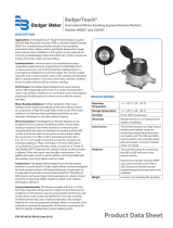
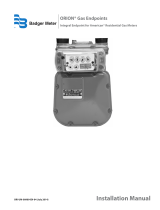
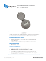
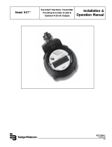
Badger Meter HR-E LCD 4-20 is a high-resolution encoder programmer. It is used to program Badger Meter high-resolution encoders. The software is compatible with Windows® 7 (or newer) operating systems. The HR-E LCD 4-20 encoder programmer allows the user to easily view and change the parameters that are programmed into the encoder, as well as program new parameters. The software also allows the user to clear the encoder reading. The IR head bracket is an optional accessory that can be used to facilitate reading and programming multiple encoders. The bracket is easy to attach and remove, and it helps to ensure that the IR head is correctly aligned with the encoder IR port.
Badger Meter HR-E LCD 4-20 is a high-resolution encoder programmer. It is used to program Badger Meter high-resolution encoders. The software is compatible with Windows® 7 (or newer) operating systems. The HR-E LCD 4-20 encoder programmer allows the user to easily view and change the parameters that are programmed into the encoder, as well as program new parameters. The software also allows the user to clear the encoder reading. The IR head bracket is an optional accessory that can be used to facilitate reading and programming multiple encoders. The bracket is easy to attach and remove, and it helps to ensure that the IR head is correctly aligned with the encoder IR port.


-
 1
1
-
 2
2
-
 3
3
-
 4
4
-
 5
5
-
 6
6
-
 7
7
-
 8
8
-
 9
9
-
 10
10
-
 11
11
-
 12
12
-
 13
13
-
 14
14
-
 15
15
-
 16
16
-
 17
17
-
 18
18
-
 19
19
-
 20
20
-
 21
21
-
 22
22
-
 23
23
-
 24
24


Badger Meter HR-E LCD 4-20 Programmer's Manual
- Category
- Noise Reduction Machine
- Type
- Programmer's Manual
- This manual is also suitable for
Badger Meter HR-E LCD 4-20 is a high-resolution encoder programmer. It is used to program Badger Meter high-resolution encoders. The software is compatible with Windows® 7 (or newer) operating systems. The HR-E LCD 4-20 encoder programmer allows the user to easily view and change the parameters that are programmed into the encoder, as well as program new parameters. The software also allows the user to clear the encoder reading. The IR head bracket is an optional accessory that can be used to facilitate reading and programming multiple encoders. The bracket is easy to attach and remove, and it helps to ensure that the IR head is correctly aligned with the encoder IR port.
Ask a question and I''ll find the answer in the document
Finding information in a document is now easier with AI
Related papers
-
Badger Meter E-Series User manual
-
 Badger Meter HR-RED User manual
-
 Badger Meter Hedland EZ-View Quick Manual
-
Badger Meter HR-LCD 4-20 Programming Manual
-
 Badger Meter BadgerTouch HREBT User manual
-
 Badger Meter Recordall Disc Series Installation guide
-
 Badger Meter Orion AM Series Installation guide
-
 Badger Meter HR-E LCD User manual
-
 Badger Meter Recordall RET Installation & Operation Manual
-
 Badger Meter ORION SE User manual


Other documents
-
Orion Water Endpoints Owner's manual
-
Badger Basket N64944-001 User manual
-
Garmin G1000 NXi - Beechcraft King Air 200/A200/B200 Reference guide
-
-
3M M170 User manual
-
-
Crown I-Tech 9000HD Owner's manual
-
Vortex VN2000 User manual
-
-