Page is loading ...

High Resolution LCD Encoders
HR-E® LCD, HR-E® LCD 4-20
LCD-UM-01482-EN-07 (April 2019)
User Manual
MPORTANTI
For proper handling of the higher reading resolution and the extended status indicator capabilities of
the HR-E LCD encoder, the following software versions are required for your reading system:
Reading Data Management Software
• ReadCenter® Data: Version 1.11.12.27 or higher (does not include extended status
indicator capabilities)
• ReadCenter Analytics and ReadCenter Analytics Mobile: Version 2.12.7.6 or later
Mobile Reading Systems
• ORS: Version 2.2.1 or later
Handheld Reading Systems
• Badger Meter Field Application Suite: Version 2.2.3 or later
• ORION Field Application route reading software: Version 2.2.3 or later
• ORION Endpoint Utility programming & quick read software: Version 2.2.2 or later
• Please contact Badger Meter Technical Support at 1-800-456-5023 or the appropriate
endpoint provider if you need assistance.

High Resolution LCD Encoders
CONTENTS
Introduction . . . . . . . . . . . . . . . . . . . . . . . . . . . . . . . . . . . . . . . . . . . . . . . . . . . . . . . . . . . . . . . . . . . . . . . . 3
Audience and Purpose . . . . . . . . . . . . . . . . . . . . . . . . . . . . . . . . . . . . . . . . . . . . . . . . . . . . . . . . . . . . . . . 3
Product Unpacking and Inspection . . . . . . . . . . . . . . . . . . . . . . . . . . . . . . . . . . . . . . . . . . . . . . . . . . . . . . . 3
License Requirements. . . . . . . . . . . . . . . . . . . . . . . . . . . . . . . . . . . . . . . . . . . . . . . . . . . . . . . . . . . . . . . . 3
Description . . . . . . . . . . . . . . . . . . . . . . . . . . . . . . . . . . . . . . . . . . . . . . . . . . . . . . . . . . . . . . . . . . . . . . . . 3
HR-E LCD . . . . . . . . . . . . . . . . . . . . . . . . . . . . . . . . . . . . . . . . . . . . . . . . . . . . . . . . . . . . . . . . . . . . . . . . 3
HR-E LCD 4-20. . . . . . . . . . . . . . . . . . . . . . . . . . . . . . . . . . . . . . . . . . . . . . . . . . . . . . . . . . . . . . . . . . . . . 3
Product Overview . . . . . . . . . . . . . . . . . . . . . . . . . . . . . . . . . . . . . . . . . . . . . . . . . . . . . . . . . . . . . . . . . . . . 4
LCD Display . . . . . . . . . . . . . . . . . . . . . . . . . . . . . . . . . . . . . . . . . . . . . . . . . . . . . . . . . . . . . . . . . . . . . . 4
Multiplier Value. . . . . . . . . . . . . . . . . . . . . . . . . . . . . . . . . . . . . . . . . . . . . . . . . . . . . . . . . . . . . . . . . . . . 4
Visual Display . . . . . . . . . . . . . . . . . . . . . . . . . . . . . . . . . . . . . . . . . . . . . . . . . . . . . . . . . . . . . . . . . . . . . 4
Units of Measure . . . . . . . . . . . . . . . . . . . . . . . . . . . . . . . . . . . . . . . . . . . . . . . . . . . . . . . . . . . . . . . . 4
9-Digit Totalization . . . . . . . . . . . . . . . . . . . . . . . . . . . . . . . . . . . . . . . . . . . . . . . . . . . . . . . . . . . . . . .4
6-Digit Totalization . . . . . . . . . . . . . . . . . . . . . . . . . . . . . . . . . . . . . . . . . . . . . . . . . . . . . . . . . . . . . . . 5
Rate of Flow . . . . . . . . . . . . . . . . . . . . . . . . . . . . . . . . . . . . . . . . . . . . . . . . . . . . . . . . . . . . . . . . . . . 5
Meter Model Information . . . . . . . . . . . . . . . . . . . . . . . . . . . . . . . . . . . . . . . . . . . . . . . . . . . . . . . . . . .5
Installing the Encoder . . . . . . . . . . . . . . . . . . . . . . . . . . . . . . . . . . . . . . . . . . . . . . . . . . . . . . . . . . . . . . . . . . 6
Bayonet Mount . . . . . . . . . . . . . . . . . . . . . . . . . . . . . . . . . . . . . . . . . . . . . . . . . . . . . . . . . . . . . . . . . . . . 6
Wire Connections . . . . . . . . . . . . . . . . . . . . . . . . . . . . . . . . . . . . . . . . . . . . . . . . . . . . . . . . . . . . . . . . . . 6
HR-E LCD . . . . . . . . . . . . . . . . . . . . . . . . . . . . . . . . . . . . . . . . . . . . . . . . . . . . . . . . . . . . . . . . . . . . . 6
HR-E LCD 4-20 . . . . . . . . . . . . . . . . . . . . . . . . . . . . . . . . . . . . . . . . . . . . . . . . . . . . . . . . . . . . . . . . . .6
HR-E LCD . . . . . . . . . . . . . . . . . . . . . . . . . . . . . . . . . . . . . . . . . . . . . . . . . . . . . . . . . . . . . . . . . . . . . . . . . . 7
Measurement Resolution . . . . . . . . . . . . . . . . . . . . . . . . . . . . . . . . . . . . . . . . . . . . . . . . . . . . . . . . . . . . . 7
Endpoint Reading Resolution . . . . . . . . . . . . . . . . . . . . . . . . . . . . . . . . . . . . . . . . . . . . . . . . . . . . . . . . . . . 7
Status Indicators . . . . . . . . . . . . . . . . . . . . . . . . . . . . . . . . . . . . . . . . . . . . . . . . . . . . . . . . . . . . . . . . . . . 8
HR-E LCD 4-20 . . . . . . . . . . . . . . . . . . . . . . . . . . . . . . . . . . . . . . . . . . . . . . . . . . . . . . . . . . . . . . . . . . . . . . . 9
Measurement Resolution . . . . . . . . . . . . . . . . . . . . . . . . . . . . . . . . . . . . . . . . . . . . . . . . . . . . . . . . . . . . . 9
Analog Output . . . . . . . . . . . . . . . . . . . . . . . . . . . . . . . . . . . . . . . . . . . . . . . . . . . . . . . . . . . . . . . . . . . 10
Endpoint Reading Resolution . . . . . . . . . . . . . . . . . . . . . . . . . . . . . . . . . . . . . . . . . . . . . . . . . . . . . . . . . . 10
Status Indicators . . . . . . . . . . . . . . . . . . . . . . . . . . . . . . . . . . . . . . . . . . . . . . . . . . . . . . . . . . . . . . . . . . 11
Page ii April 2019LCD-UM-01482-EN-07

Introduction
INTRODUCTION
This is the user manual for the High Resolution (HR) LCD encoders.
Audience and Purpose
This manual is intended to be used by utilities for installing and using HR-E LCD and HR-E LCD 4-20 encoders.
Product Unpacking and Inspection
Upon opening the shipping container, visually inspect the product and applicable accessories for any physical damage such
as scratches, loose or broken parts, or any other sign of damage that may have occurred during shipment.
OTE:N If damage is found, request an inspection by the carrier’s agent within 48 hours of delivery and file a claim with the
carrier. A claim for equipment damage in transit is the sole responsibility of the purchaser.
License Requirements
This device complies with Part 15 of the FCC Rules. Operation of this device is subject to the following two conditions: (1) This
device may not cause harmful interference, and (2) this device must accept any interference received, including interference
that may cause undesired operation. Any changes made by the user not approved by Badger Meter can void the user’s
authority to operate the equipment.
DESCRIPTION
High resolution encoders are fully electronic, solid-state devices with no moving parts. The devices come standard as factory
programmed, with the option for programming in the field. Programming is performed through the device IR port via a
computer. The programming kit (PN: 67660-001) can be ordered through Customer Service.
OTE:N Refer to the document, High Resolution LCD Encoder Programmer Manual, available at www.badgermeter.com, for
programming instructions.
HR-E LCD
The HR-E LCD is a permanently sealed, electronic LCD absolute encoder with field-programmable options that produces an
industry standard ASCII encoded output. HR-E LCD encoders are designed for use with all current Badger Meter Recordall®
Disc, Turbo Series, Compound Series, Combo Series and Fire Service meters and assemblies. The encoders provide
connectivity with Badger Meter ORION®
and GALAXY® AMR/AMI endpoints and other AMR/AMI technology solutions
approved by Badger Meter.
HR-E LCD 4-20
The HR-E LCD 4-20 is a permanently sealed, electronic LCD absolute encoder that produces an industry standard ASCII
encoded output as well as an analog 4-20 mA DC output signal with a dual output wire design. HR-E LCD 4-20 encoders are
designed for use with all current Badger Meter Recordall® Disc, Turbo Series, Compound Series, Combo Series and Fire Service
meters and assemblies. The encoders provide connectivity with Badger Meter ORION
AMR/AMI endpoints and other AMR/AMI
technology solutions approved by Badger Meter.
Page 3 April 2019 LCD-UM-01482-EN-07

Product Overview
PRODUCT OVERVIEW
LCD Display
HR-LCD encoders have a nine-digit Liquid Crystal Display (LCD) to show consumption, flow and alarm information.
There is no need to activate the display. The display automatically toggles between consumption (segmented leak detector in
this mode), rate of flow and meter model.
OTE:N Devices are shipped in storage mode so that a meter status alarm is not triggered. In storage mode, the meter model
screen is displayed.
Multiplier Value
Depending on the meter model, size and unit of measure, a multiplier value may also be shown. Multiply the displayed value
by the multiplier value to calculate the reading to the nearest gallon, cubic foot, or cubic meter.
Example: 123456 (displayed value) x 10 (multiplier value) = 1234560
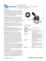
Extended Visual
Reading Resolution
Typical Billing
Segments
Status
Indicators
IR Programming
Port
00/00
4-Digit
Date Code
E LCD
HR
Multiplier Value
(x10, x100, x1000, x10,000)
In 6-digit mode, the
last digit is a dashed
line that becomes a
ow nder
Figure 1: HR-E LCD encoder face
Visual Display
Units of Measure
The units of measure are factory-programmed and user-programmable. Options include U.S. gallons, Imperial gallons, cubic
feet, cubic meters and liters.
9-Digit Totalization
The consumption display includes all nine digits and a decimal point (based on meter model, size and unit of measure). The
displayed value is the sum of the forward flow minus any reverse flow. This screen displays for 45 seconds.
Model 25 Disc Series Meter Calibrated in Gallons
4
GAL
Page 4 April 2019LCD-UM-01482-EN-07

Product Overview
6-Digit Totalization
6-digit totalization mode is used to represent the typical 6 wheel odometer registration as seen on a mechanical encoder.
When water is flowing through the meter, the display includes a series of moving segments to represent a flow finder. This
screen displays for 5 seconds. 6-digit totalization mode is active on the HR-E LCD and HR-E LCD 4-20 encoders.
Model 25 Disc Series Meter Calibrated in Gallons
4
X10
GAL
In 9- and 6-digit totalization mode, the display also includes indicator lines above and below the digits to provide the
electronic equivalent of the white and black number wheels on a mechanical encoder. The segmented lines above and below
the numbers represent what the white number wheels do for mechanical encoders—typical utility standard billing units.
For more detailed information on the visual totalizer displays, see the application brief, How to Read an Encoder, available at
www.badgermeter.com.
Rate of Flow
The rate of flow is factory programmed to gallons per minute. The device displays both the unit of measure and rate of flow.
The rate of flow display is shown without leading zeros. A reverse flow is indicated by a minus sign before the flow rate. The
displayed rate will be based on the average flow rate for the prior minute (since the last time the flow rate was displayed). This
screen displays for 5 seconds.
Model 25 Disc Series Meter Calibrated in Gallons
4
GAL
RATE /MIN
Meter Model Information
The meter model information screen identifies the meter for which the encoder was programmed and displays for 5 seconds.
The display shows the meter type (turbo, disc, compound), the meter model, digit resolution from the device, and the unit of
measure (gal, ft
3,
m
3
, imp, liter). Disc meters are indicated by a d, Turbo meters are indicated by a stylized T (only the right half
of the horizontal line appears) and Compound meters are indicated by a C. See examples below:
Model 25 Disc Series Meter
Calibrated in Gallons
Model 450 Turbo Series Meter
Calibrated in Gallons
2 in. Low Side Compound Series
Meter Calibrated in Cubic Feet
GAL GAL
FT3
The meter model information screen also displays the digit resolution sent from the encoder.
OTE:N Resolution sent to the reading data management software is dependent on the endpoint connected to the device.
See "Endpoint Reading Resolution" on page 7 and page 10 for more information.
Page 5 April 2019 LCD-UM-01482-EN-07

Installing the Encoder
INSTALLING THE ENCODER
Bayonet Mount
The fully potted assembly has a bayonet mount compatible with all Recordall Disc, Turbo Series, Compound Series, Combo
Series and Fire Series meters and assemblies.
The bayonet mount positions the encoder in any of four orientations for visual reading convenience. The device can be
removed from the meter without disrupting water service.
The device is permanently sealed to eliminate the intrusion of moisture, dirt or other contaminants, and is suitable for
installation in all environments, including meter pits subject to continuous submergence.
Install the device on the water meter and secure it using the tamper-proof screw provided.
Wire Connections
The following connection options are available. For more information on in-line connectors, refer to the document, ORION
Water Endpoints Installation Manual, available at www.badgermeter.com.
HR-E LCD
The HR-E LCD encoder has a single cable, available with three different wiring options. Refer to Figure 2.
• In-line connector
• Flying lead for field splice connection
• Prewired to an AMR/AMI endpoint
Encoder Cable with In-line Connector
Flying Lead
RED - Power
GREEN - Data
BLACK - Ground
Prewired to AMR/AMI Endpoint
Figure 2: HR-E LCD wiring options
HR-E LCD 4-20
The HR-E LCD 4-20 encoder is available with dual output wire connections. Refer to Figure 3.
Encoder side cable
• In-line connector
• Flying lead for field splice connection
4-20 side cable
• Flying lead for field splice connection
4-20 mA Cable
RED - Loop/External Power +
BLACK - Loop Return/External Power –
Encoder Cable with In-line Connector
4-20 mA Cable
RED - Power
GREEN - Data
BLACK - Ground
Encoder Cable with Flying Lead
RED - Loop/External Power +
BLACK - Loop Return/External Power –
Figure 3: HR-E LCD 4-20 wiring options
Page 6 April 2019LCD-UM-01482-EN-07

HR-E LCD
HRE LCD
The HR-E LCD is a permanently sealed, electronic LCD absolute encoder which produces an industry standard ASCII
encoded output.
Measurement Resolution
Recordall
Disc Series
Size (in.)
9-Digit Encoder
Gallons Cubic Feet Cubic Meters
LP 5/8, 5/8 x 3/4 0.01 0.001 0.0001
M25 5/8, 5/8 x 3/4 0.01 0.001 0.0001
M35 3/4 0.01 0.001 0.0001
M40 1 0.01 0.001 0.0001
M55 1 0.01 0.001 0.0001
M70 1 0.01 0.001 0.0001
M120 1-1/2 0.1 0.01 0.001
M170 2 0.1 0.01 0.001
Recordall
Turbo Series
Size (in.)
9-Digit Encoder
Gallons Cubic Feet Cubic Meters
T160 1-1/2 0.1 0.01 0.001
T200 2 0.1 0.01 0.001
T450 3 0.1 0.01 0.001
T1000 4 0.1 0.01 0.001
T2000 6 1 0.1 0.01
T3500 8 1 0.1 0.01
T5500 10 1 0.1 0.01
T6200 12 10 1 0.01
T6600 16 10 1 0.01
T10000 20 10 1 0.01
Recordall Compound
Series
Size (in.)
9-Digit Encoder
Gallons Cubic Feet Cubic Meters
High Side T200 2 0.1 0.01 0.001
Low Side M25 2 0.01 0.001 0.0001
High Side T450 3 0.1 0.01 0.001
Low Side M25 3 0.01 0.001 0.0001
High Side T1000 4 0.1 0.01 0.001
Low side M35 4 0.01 0.001 0.0001
High Side T2000 6 1 0.1 0.01
Low Side M35 6 0.01 0.001 0.0001
High Side T3500 8 1 0.1 0.01
Low side M120 8 0.1 0.01 0.001
Endpoint Reading Resolution
MPORTANTI
The standard electronic encoder output resolution of the HR-E LCD encoder is 9 digits. Though the encoder output is 9-digit
resolution, the reading resolution sent to the reading software is dependent on the endpoint that the encoder is connected to.
Readings reported from the endpoints are the left-most significant digits of the encoder reading.
Endpoint Technology Reading Resolution Reported to Reading Software
ORION Cellular 9-digit reading, plus the extended message capability
ORION Migratable (ME)/Fixed Network (SE) 8-digit reading, plus the extended message capability
ORION Classic (CE) 7-digit reading
GALAXY 6-digit reading
See the application brief, HR-E LCD Encoder Test Circle Codes, available at www.badgermeter.com, for the appropriate test circle
code/reading resolutions for the HR-E LCD encoder with ORION or GALAXY endpoints. Other output options are available for
certain applications.
Page 7 April 2019 LCD-UM-01482-EN-07

HR-E LCD
Status Indicators
Status indicators are sent as part of the encoder message to AMR/AMI systems that are capable of receiving an extended
message, such as ORION Cellular, Fixed Network (SE) and Migratable (ME) endpoints. The details can also be read through an
IR interface.
Status indicators appear in the display as symbols that illuminate when the condition is active and dim when the condition
is eliminated.
All HR-E LCD encoders are delivered in storage mode so that a meter alarm is not triggered. During storage mode, the meter
model displays on the encoder. As water begins to flow through the meter, the encoder switches from storage mode to
normal operation upon sensing two (2) revolutions of the meter magnet.
The following chart indicates the HR-E LCD encoder conditions when connected to a Badger Meter ORION Cellular, Fixed
Network or Migratable endpoint. The chart does not apply to ORION Classic (CE) or GALAXY endpoints, or HR-E LCD encoders
programmed to a resolution lower than a 9-digit output. The HR-E LCD encoder displays the information, but the extra
information is not reported through the endpoints.
Status Indicator Icon Status Description HR-E LCD Display
HR-E LCD with ORION Cellular
or Fixed Network* and
Migratable* Endpoints
*Firmware version 1.8 or higher required
Meter functioning
correctly
Encoder operating correctly.
Continuous display on encoder as
long as no other status indicators
are triggered.
Indicator status not sent to
the endpoint.
Encoder alarm
Several potential conditions
may exist, including:
Encoder removal
Temperature limit exceeded
(34…140° F)
Magnetic tamper
Encoder alarm remains active for
35 days. The alarm automatically
clears after 35 days if any of the 3
conditions has not recurred.
Encoder alarm sent to the endpoint.
Reverse flow
Encoder detects reverse flow.
Reverse flow alarm remains active
for 35 days. The alarm automatically
clears after 35 days if reverse flow
condition has not recurred.
Encoder detects reverse flow
and sends alarm message to
the endpoint.
Suspected leak
Encoder detects 24 hours
without one 15-minute
interval of no flow.
The alarm clears automatically
when a 15-minute no-flow
interval occurs.
Encoder detects suspected leak
and sends alarm message to
the endpoint.
If condition clears before
message is sent to the endpoint,
it is not reported.
30 day no usage
No measured flow in past
30 days.
The alarm is automatically cleared
once flow occurs.
Encoder detects 30 days no usage
and sends alarm to the endpoint.
End of life
battery indicator
Indicated battery life based on
pre-calculated consumption.
Alarm activated at 19 years and
does not clear.
Encoder sends alarm to the endpoint.
Page 8 April 2019LCD-UM-01482-EN-07

HR-E LCD 4-20
HRE LCD 420
The HR-E LCD 4-20 is a permanently sealed, electronic LCD absolute encoder which produces an industry standard ASCII
encoded output as well as a 4-20 mA DC output signal through a dual output wire design.
Measurement Resolution
Standard encoded output is 9 digits. The 4-20 signal from the encoder is proportional to the flow of fluid passing through the
meter. Power for the 4-20 output signal device can be obtained from a 9…50V DC control loop. The default 20 mA setting of
the signal is defined in the resolution chart.
Recordall Disc Series Size (in.)
Encoder Output Analog Output
9-dial (gal) 9-dial (ft
3
) 9-dial (m
3
) 20 mA Set point (gpm)
LP 5/8, 5/8 x 3/4 0.01 0.001 0.0001 20
M25 5/8, 5/8 x 3/4 0.01 0.001 0.0001 25
M35 3/4 0.01 0.001 0.0001 35
M40 1 0.01 0.001 0.0001 40
M55 1 0.01 0.001 0.0001 55
M70 1 0.01 0.001 0.0001 70
M120 1-1/2 0.1 0.01 0.001 120
M170 2 0.1 0.01 0.001 170
Recordall
Turbo Series
Size (in.)
Encoder Output Analog Output
9-dial (gal) 9-dial (ft
3
) 9-dial (m
3
) 20 mA Set point (gpm)
T160 1-1/2 0.1 0.01 0.001 200
T200 2 0.1 0.01 0.001 310
T450 3 0.1 0.01 0.001 550
T1000 4 0.1 0.01 0.001 1250
T2000 6 1 0.1 0.01 2500
T3500 8 1 0.1 0.01 4500
T5500 10 1 0.1 0.01 7000
T6200 12 10 1 0.01 8800
T6600 16 10 1 0.01 13200
T10000 20 10 1 0.01 19800
Recordall Compound
Series
Size (in.)
Encoder Output Analog Output
9-dial (gal) 9-dial (ft
3
) 9-dial (m
3
) 20 mA Set point (gpm)
High Side T200 2 0.1 0.01 0.001 200
Low Side M25 2 0.01 0.001 0.0001 25
High Side T450 3 0.1 0.01 0.001 450
Low Side M25 3 0.01 0.001 0.0001 25
High Side T1000 4 0.1 0.01 0.001 1000
Low side M35 4 0.01 0.001 0.0001 35
High Side T2000 6 1 0.1 0.01 2000
Low Side M35 6 0.01 0.001 0.0001 35
High Side T3500 8 1 0.1 0.01 —
Low side M120 8 0.1 0.01 0.001 —
Page 9 April 2019 LCD-UM-01482-EN-07

HR-E LCD 4-20
Analog Output
• The input pulses generated within the transmitter assembly are converted to a standard 4-20 mA control signal.
• This signal is proportional to the flow of fluid passing through the flow meter.
• Power for the device can be obtained from a 9…50V DC control loop.
• The default 20mA setting of the signal is defined in the registration section.
Endpoint Reading Resolution
MPORTANTI
The standard electronic encoder output resolution of the HR-E LCD 4-20 encoder is 9 digits. Though the encoder output is 9-digit
resolution, the reading resolution sent to the reading software is dependent on the endpoint that the encoder is connected to.
Readings reported from the endpoints are the left-most significant digits of the encoder reading.
Endpoint Technology Reading Resolution Reported to Reading Software
ORION Cellular 9-digit reading, plus the extended message capability
ORION Migratable (ME)/Fixed Network (SE) 8-digit reading, plus the extended message capability
ORION Classic (CE) 7-digit reading
See the application brief, HR-E LCD Encoder Test Circle Codes, available at www.badgermeter.com, for the appropriate test circle
code/reading resolutions for the encoder with ORION endpoints. Other output options are available for certain applications.
Page 10 April 2019LCD-UM-01482-EN-07

HR-E LCD 4-20
Status Indicators
Status indicators are sent as part of the encoder message to AMR/AMI systems that are capable of receiving an extended
message, such as ORION Cellular, Fixed Network (SE) and Migratable (ME) endpoints. The details can also be read through an
IR interface.
Status indicators appear in the display as symbols that illuminate when the condition is active and dim when the condition
is eliminated.
All HR-E LCD 4-20 encoders are delivered in storage mode so that a meter alarm is not triggered. During storage mode, the
meter model displays on the encoder. As water begins to flow through the meter, the encoder switches from storage mode to
normal operation upon sensing two (2) revolutions of the meter magnet.
The following chart indicates the HR-E LCD 4-20 encoder conditions when connected to a Badger Meter ORION Cellular, Fixed
Network or Migratable endpoint. The chart does not apply to ORION Classic (CE) or GALAXY endpoints, or HR-E LCD 4-20
encoders programmed to a resolution lower than a 9-digit output. The HR-E LCD 4-20 encoder displays the information, but
the extra information is not reported through the endpoints.
Status Indicator Icon Status Description HR-E LCD 4-20 Display
HR-E LCD 4-20 with ORION
Cellular or Fixed Network* and
Migratable* Endpoints
*Firmware version 1.8 or higher required
Meter functioning
correctly
Encoder operating correctly.
Continuous display on encoder
as long as no other status
indicators are triggered.
Indicator status not sent to
the endpoint.
Encoder alarm
Several potential conditions
may exist, including:
Encoder removal
Temperature limit exceeded
(34…140° F)
Magnetic tamper
Encoder alarm remains active for
35 days. The alarm automatically
clears after 35 days if any of the 3
conditions has not recurred.
Encoder alarm sent to the endpoint.
Reverse flow
Encoder detects reverse flow.
Reverse flow alarm remains
active for 35 days. The alarm
automatically clears after 35
days if reverse flow condition has
not recurred.
Encoder detects reverse flow and sends
alarm message to the endpoint.
Suspected leak
Encoder detects 24 hours
without one 15-minute
interval of no flow.
The alarm clears automatically
when a 15-minute no-flow
interval occurs.
Encoder detects suspected leak and
sends alarm message to the endpoint.
If condition clears before message is
sent to the endpoint, it is not reported.
30 day no usage
No measured flow in past
30 days.
The alarm is automatically
cleared once flow occurs.
Encoder detects 30 days no usage and
sends alarm to the endpoint.
End of life
battery indicator
Indicated battery life based on
pre-calculated consumption.
Alarm activated at 19 years and
does not clear.
Encoder sends alarm to the endpoint.
Page 11 April 2019 LCD-UM-01482-EN-07

High Resolution LCD Encoders, HR-E® LCD, HR-E® LCD 4-20
www.badgermeter.com
GALAXY, HR-E, Making Water Visible, ORION, ReadCenter and Recordall are registered trademarks of Badger Meter, Inc. Other trademarks appearing in this document are the
property of their respective entities. Due t continuous research, product improvements and enhancements, Badger Meter reserves the right to change product or system
specications without notice, except to the extent an outstanding contractual obligation exists. © 2019 Badger Meter, Inc. All rights reserved.
Legacy Document Number: LCD-IOM-01-EN
SMART WATER IS BADGER METER
The Americas | Badger Meter | 4545 West Brown Deer Rd | PO Box 245036 | Milwaukee, WI 53224-9536 | 800-876-3837 | 414-355-0400
México | Badger Meter de las Americas, S.A. de C.V. | Pedro Luis Ogazón N°32 | Esq. Angelina N°24 | Colonia Guadalupe Inn | CP 01050 | México, DF | México | +52-55-5662-0882
Europe, Eastern Europe Branch Oce (for Poland, Latvia, Lithuania, Estonia, Ukraine, Belarus) | Badger Meter Europe | ul. Korfantego 6 | 44-193 Knurów | Poland | +48-32-236-8787
Europe, Middle East and Africa | Badger Meter Europa GmbH | Nurtinger Str 76 | 72639 Neuen | Germany | +49-7025-9208-0
Europe, Middle East Branch Oce | Badger Meter Europe | PO Box 341442 | Dubai Silicon Oasis, Head Quarter Building, Wing C, Oce #C209 | Dubai / UAE | +971-4-371 2503
Slovakia | Badger Meter Slovakia s.r.o. | Racianska 109/B | 831 02 Bratislava, Slovakia | +421-2-44 63 83 01
Asia Pacic | Badger Meter | 80 Marine Parade Rd | 19-07 Parkway Parade | Singapore 449269 | +65-63464836
Switzerland | Badger Meter Swiss AG | Mittelholzerstrasse 8 | 3006 Bern | Switzerland | +41-31-932 01 11
/