Page is loading ...

NANO-GM45A EPIC SBC
Page I
IEI Technology Corp.
User Manual
NANO-GM45A
MODEL:
EPIC Motherboard Supports Intel® Core™2 Duo CPU,
VGA/LVDS/HDTV-out, Dual GbE, USB 2.0 and Two SATA II
Rev. 1.01 - 6 November, 2009
NANO-GM45A CPU Card


NANO-GM45A EPIC SBC
Page III
Copyright
COPYRIGHT NOTICE
The information in this document is subject to change without prior notice in order to
improve reliability, design and function and does not represent a commitment on the part
of the manufacturer.
In no event will the manufacturer be liable for direct, indirect, special, incidental, or
consequential damages arising out of the use or inability to use the product or
documentation, even if advised of the possibility of such damages.
This document contains proprietary information protected by copyright. All rights are
reserved. No part of this manual may be reproduced by any mechanical, electronic, or
other means in any form without prior written permission of the manufacturer.
TRADEMARKS
All registered trademarks and product names mentioned herein are used for identification
purposes only and may be trademarks and/or registered trademarks of their respective
owners.

NANO-GM45A EPIC SBC
Page IV
Table of Contents
1 INTRODUCTION.......................................................................................................... 1
1.1 INTRODUCTION........................................................................................................... 2
1.2 CONNECTORS ............................................................................................................. 3
1.3 DIMENSIONS............................................................................................................... 3
1.3.1 Board Dimensions.............................................................................................. 3
1.3.2 External Interface Panel Dimensions................................................................ 5
1.4 DATA FLOW................................................................................................................ 6
1.5 TECHNICAL SPECIFICATIONS ...................................................................................... 7
2 UNPACKING................................................................................................................. 9
2.1 ANTI-STATIC PRECAUTIONS...................................................................................... 10
2.2 UNPACKING PRECAUTIONS....................................................................................... 10
2.3 PACKING LIST............................................................................................................11
2.3.1 Optional Items.................................................................................................. 12
3 CONNECTORS ........................................................................................................... 13
3.1 PERIPHERAL INTERFACE CONNECTORS..................................................................... 14
3.1.1 NANO-GM45A Layout..................................................................................... 14
3.1.2 Peripheral Interface Connectors ..................................................................... 14
3.1.3 External Interface Panel Connectors............................................................... 15
3.2 INTERNAL PERIPHERAL CONNECTORS ...................................................................... 16
3.2.1 ATX Power Supply Enable Connector............................................................. 16
3.2.2 Audio Connector .............................................................................................. 17
3.2.3 Backlight Inverter Connector .......................................................................... 18
3.2.4 12V Power Connector...................................................................................... 19
3.2.5 Fan Connectors................................................................................................ 20
3.2.6 Front Panel Connector .................................................................................... 21
3.2.7 IEEE 1394a Connectors .................................................................................. 22
3.2.8 LVDS LCD Connector ..................................................................................... 23
3.2.9 MCU Firmware Update Connector................................................................. 25
3.2.10 PCIe Mini Card Slot ...................................................................................... 25

NANO-GM45A EPIC SBC
Page V
3.2.11 SATA Drive Connectors.................................................................................. 27
3.2.12 SATA Power Connector (+5V)....................................................................... 28
3.2.13 Serial Port Connectors (COM 1 ~ COM 4)................................................... 29
3.2.14 TV Out Connector.......................................................................................... 30
3.3 EXTERNAL PERIPHERAL INTERFACE CONNECTOR PANEL ......................................... 31
3.3.1 HDMI Connector............................................................................................. 32
3.3.2 LAN Connectors............................................................................................... 33
3.3.3 USB Connectors............................................................................................... 34
3.3.4 VGA Connector................................................................................................ 34
4 INSTALLATION ......................................................................................................... 36
4.1 ANTI-STATIC PRECAUTIONS...................................................................................... 37
4.2 INSTALLATION CONSIDERATIONS.............................................................................. 38
4.2.1 Installation Notices.......................................................................................... 38
4.2.2 Installation Checklist....................................................................................... 39
4.3 UNPACKING.............................................................................................................. 40
4.4 CPU, CPU COOLING KIT AND SO-DIMM INSTALLATION........................................ 40
4.4.1 Socket P CPU Installation ............................................................................... 40
4.4.2 Socket P Cooling Kit Installation..................................................................... 42
4.4.3 SO-DIMM Installation..................................................................................... 43
4.5 JUMPER SETTINGS .................................................................................................... 44
4.5.1 AT Power Select Jumper Settings..................................................................... 45
4.5.2 Clear CMOS Jumper........................................................................................ 46
4.5.3 LVDS Panel Resolution Jumper....................................................................... 47
4.5.4 LVDS Voltage Selection.................................................................................... 48
4.6 CHASSIS INSTALLATION............................................................................................ 50
4.6.1 Airflow.............................................................................................................. 50
4.6.2 Motherboard Installation................................................................................. 50
4.7 INTERNAL PERIPHERAL DEVICE CONNECTIONS........................................................ 50
4.7.1 AT Power Connection...................................................................................... 50
4.7.2 ATX Power Connection.................................................................................... 52
4.7.3 Audio Kit Installation....................................................................................... 56
4.7.4 SATA Drive Connection ................................................................................... 57
4.8 EXTERNAL PERIPHERAL INTERFACE CONNECTION ................................................... 58
4.8.1 LAN Connection (Single Connector)............................................................... 58

NANO-GM45A EPIC SBC
Page VI
4.8.2 USB Connection (Dual Connector)................................................................. 59
4.8.3 VGA Monitor Connection ................................................................................ 60
4.9 SOFTWARE INSTALLATION ........................................................................................ 61
5 BIOS SCREENS........................................................................................................... 64
5.1 INTRODUCTION......................................................................................................... 65
5.1.1 Starting Setup................................................................................................... 65
5.1.2 Using Setup...................................................................................................... 65
5.1.3 Getting Help..................................................................................................... 66
5.1.4 Unable to Reboot After Configuration Changes.............................................. 66
5.1.5 BIOS Menu Bar................................................................................................ 66
5.2 MAIN........................................................................................................................ 67
5.3 ADVANCED............................................................................................................... 68
5.3.1 CPU Configuration.......................................................................................... 69
5.3.2 IDE Configuration........................................................................................... 70
5.3.2.1 IDE Master, IDE Slave ............................................................................. 72
5.3.3 AHCI Configuration......................................................................................... 76
5.3.3.1 AHCI Port n .............................................................................................. 77
5.3.4 Remote Access Configuration.......................................................................... 78
5.3.5 USB Configuration........................................................................................... 81
5.3.6 Power Configuration ....................................................................................... 83
5.3.7 Super IO Configuration ................................................................................... 84
5.4 PCI/PNP................................................................................................................... 86
5.5 BOOT........................................................................................................................ 88
5.5.1 Boot Settings Configuration............................................................................. 89
5.6 SECURITY................................................................................................................. 91
5.7 CHIPSET ................................................................................................................... 91
5.7.1 Northbridge Configuration.............................................................................. 93
5.7.2 Southbridge Configuration .............................................................................. 95
5.8 EXIT......................................................................................................................... 96
A BIOS MENU OPTIONS............................................................................................. 98
B TERMINOLOGY...................................................................................................... 101
C WATCHDOG TIMER .............................................................................................. 106
D COMPATIBILITY.................................................................................................... 109

NANO-GM45A EPIC SBC
Page VII
D.1 COMPATIBLE OPERATING SYSTEMS ........................................................................110
D.2 COMPATIBLE PROCESSORS......................................................................................111
D.3 COMPATIBLE MEMORY MODULES ..........................................................................111
E HAZARDOUS MATERIALS DISCLOSURE ........................................................113
E.1 HAZARDOUS MATERIAL DISCLOSURE TABLE FOR IPB PRODUCTS CERTIFIED AS
ROHS COMPLIANT UNDER 2002/95/EC WITHOUT MERCURY ......................................114

NANO-GM45A EPIC SBC
Page VIII
List of Figures
Figure 1-1: NANO-GM45A..............................................................................................................2
Figure 1-2: Connectors ..................................................................................................................3
Figure 1-3: NANO-GM45A Dimensions (mm)...............................................................................4
Figure 1-4: External Interface Panel Dimensions (mm)..............................................................5
Figure 1-5: Data Flow Block Diagram...........................................................................................6
Figure 3-1: Connector and Jumper Locations...........................................................................14
Figure 3-2: ATX Power Supply Enable Connector Location....................................................17
Figure 3-3: Audio Connector Location.......................................................................................18
Figure 3-4: Panel Backlight Connector Pinout Locations........................................................19
Figure 3-5: CPU 12V Power Connector Location......................................................................20
Figure 3-6: +12V Fan Connector Locations...............................................................................21
Figure 3-7: Front Panel Connector Location .............................................................................22
Figure 3-8: IEEE 1394a Connector Locations............................................................................23
Figure 3-9: LVDS LCD Connector Pinout Location...................................................................24
Figure 3-10: MCU Firmware Update Connector Location.........................................................25
Figure 3-11: PCIe Mini Card Slot Location.................................................................................26
Figure 3-12: SATA Drive Connector Locations.........................................................................27
Figure 3-13: 5V Power Connector Locations.............................................................................28
Figure 3-14: COM Connector Pinout Location ..........................................................................29
Figure 3-15: TV Connector Pinout Location ..............................................................................31
Figure 3-16: NANO-GM45A External Peripheral Interface Connector.....................................32
Figure 3-17: RJ-45 Ethernet Connector......................................................................................33
Figure 3-18: VGA Connector .......................................................................................................35
Figure 4-1: Make sure the CPU socket retention screw is unlocked ......................................41
Figure 4-2: Lock the CPU Socket Retention Screw...................................................................42
Figure 4-3: Cooling Kit Support Bracket....................................................................................43
Figure 4-4: SO-DIMM Installation................................................................................................44
Figure 4-5: Jumper Locations.....................................................................................................44
Figure 4-6: AT Power Select Jumper Location..........................................................................46
Figure 4-7: Clear CMOS Jumper .................................................................................................47
Figure 4-8: LVDS Panel Resolution Jumper Pinout Locations................................................48

NANO-GM45A EPIC SBC
Page IX
Figure 4-9: LVDS Voltage Selection Jumper Pinout Locations...............................................49
Figure 4-10: Power Cable to Motherboard Connection............................................................51
Figure 4-11: Connect Power Cable to Power Supply................................................................52
Figure 4-12: Power Cable to Motherboard Connection............................................................53
Figure 4-13: Connect Power Cable to ATX Adapter Cable.......................................................54
Figure 4-14: Connect ATX Power Adapter Cable to Power Supply.........................................55
Figure 4-15: Connect ATX Power Cable to Motherboard .........................................................55
Figure 4-16: Audio Kit Cable Connection ..................................................................................56
Figure 4-17: SATA Drive Cable Connection...............................................................................57
Figure 4-18: SATA Power Drive Connection..............................................................................58
Figure 4-19: LAN Connection......................................................................................................59
Figure 4-20: USB Connector........................................................................................................60
Figure 4-21: VGA Connector .......................................................................................................61
Figure 4-22: Introduction Screen................................................................................................62
Figure 4-23: Available Drivers.....................................................................................................63

NANO-GM45A EPIC SBC
Page X
List of Tables
Table 1-1: Technical Specifications..............................................................................................8
Table 3-1: Peripheral Interface Connectors...............................................................................15
Table 3-2: Rear Panel Connectors..............................................................................................16
Table 3-3: ATX Power Supply Enable Connector Pinouts .......................................................17
Table 3-4: Audio Connector Pinouts ..........................................................................................18
Table 3-5: Panel Backlight Connector Pinouts..........................................................................19
Table 3-6: CPU 12V Power Connector Pinouts..........................................................................20
Table 3-7: +12V Fan Connector Pinouts.....................................................................................21
Table 3-8: Front Panel Connector Pinouts.................................................................................22
Table 3-9: IEEE 1394a Connector Pinouts.................................................................................23
Table 3-10: LVDS LCD Port Connector Pinouts........................................................................24
Table 3-11: MCU Firmware Update Connector Pinouts............................................................25
Table 3-12: PCIe Mini Card Slot Pinouts ....................................................................................27
Table 3-13: SATA Drive Connector Pinouts...............................................................................28
Table 3-14: 5V Power Connector Pinouts ..................................................................................28
Table 3-15: COM Connector Pinouts..........................................................................................30
Table 3-16: TV Port Connector Pinouts......................................................................................31
Table 3-17: HDMI Connector Pinouts .........................................................................................32
Table 3-18: LAN Pinouts ..............................................................................................................33
Table 3-19: RJ-45 Ethernet Connector LEDs.............................................................................33
Table 3-20: USB Port Connector Pinouts (USB1_2)..................................................................34
Table 3-21: USB Port Connector Pinouts (USB3_4)..................................................................34
Table 3-22: VGA Connector Pinouts...........................................................................................35
Table 4-1: Jumpers.......................................................................................................................45
Table 4-2: AT Power Select Jumper Settings ............................................................................45
Table 4-3: Clear CMOS Jumper Settings....................................................................................47
Table 4-4: LVDS Panel Resolution Jumper Settings.................................................................48
Table 4-5: LVDS Voltage Selection Jumper Settings................................................................49
Table 5-1: BIOS Navigation Keys................................................................................................66

NANO-GM45A EPIC SBC
Page XI
List of BIOS Menus
BIOS Menu 1: Main.......................................................................................................................67
BIOS Menu 2: Advanced..............................................................................................................69
BIOS Menu 3: CPU Configuration...............................................................................................69
BIOS Menu 4: IDE Configuration.................................................................................................70
BIOS Menu 5: IDE Master and IDE Slave Configuration...........................................................72
BIOS Menu 6: AHCI Configuration..............................................................................................77
BIOS Menu 7: AHCI Port n Configuration Menu........................................................................78
BIOS Menu 8: Remote Access Configuration............................................................................79
BIOS Menu 9: USB Configuration...............................................................................................81
BIOS Menu 10: APM Configuration.............................................................................................83
BIOS Menu 11: Super IO Configuration......................................................................................84
BIOS Menu 12: PCI/PnP Configuration.......................................................................................86
BIOS Menu 13: Boot.....................................................................................................................88
BIOS Menu 14: Boot Settings Configuration.............................................................................89
BIOS Menu 15: Security...............................................................................................................91
BIOS Menu 16: Chipset................................................................................................................92
BIOS Menu 17:Northbridge Chipset Configuration...................................................................93
BIOS Menu 18:Southbridge Chipset Configuration..................................................................95
BIOS Menu 19:Exit........................................................................................................................96


NANO-GM45A EPIC SBC
Page 1
1 Introduction
Chapter
1

NANO-GM45A EPIC SBC
Page 2
1.1 Introduction
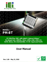
Figure 1-1: NANO-GM45A
The NANO-GM45A EPIC motherboard is a Socket P Intel® Core™2 Duo and Intel®
Celeron® M processor platform. Both 45nm core (Penryn) and 65nm core (Merom –
Santa Rosa) processors are supported.
Up to two 2.0 GB 667 MHz or 800 MHz un-buffered DDR2 SDRAM SO-DIMM are
supported by the Intel® GM45 graphics memory controller hub (GMCH). The Intel® GM45
GMCH also supports 18-bit or 24-bit dual-channel LVDS, analog CRT and HDTV output.
The integrated Intel® ICH9M I/O controller hub (ICH) supports two SATA II drives with
data transfer speeds of 3.0 Gbps. Four USB 2.0 channels and one expansion PCIe mini
socket provide flexible expansion options. High Definition Audio (HDA) support ensures
HDA devices can be easily implemented on the NANO-GM45A.

NANO-GM45A EPIC SBC
Page 3
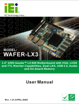
1.2 Connectors
The connectors on the NANO-GM45A are shown in the figure below.
Figure 1-2: Connectors
1.3 Dimensions
1.3.1 Board Dimensions
The dimensions of the board are listed below:
Length: 115 mm
Width: 165 mm

NANO-GM45A EPIC SBC
Page 4
Figure 1-3: NANO-GM45A Dimensions (mm)

NANO-GM45A EPIC SBC
Page 5
1.3.2 External Interface Panel Dimensions
External peripheral interface connector panel dimensions are shown in 4Figure 1-4.
Figure 1-4: External Interface Panel Dimensions (mm)

NANO-GM45A EPIC SBC
Page 6
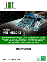
1.4 Data Flow
4Figure 1-5 shows the data flow between the two on-board chipsets and other components
installed on the motherboard and described in the following sections of this chapter.
Figure 1-5: Data Flow Block Diagram

NANO-GM45A EPIC SBC
Page 7
1.5 Technical Specifications
NANO-GM45A technical specifications are listed in table below.
Specification NANO-GM45A
Form Factor
EPIC
Socket
Socket P
CPU Supported
45 nm Socket P Intel® Core™2 Duo processor
45 nm Socket P Intel® Celeron® M processor
Front Side Bus (FSB)
1066 MHz (Max.), 800 MHz or 533 MHz
Northbridge Chipset
Intel® GM45
Southbridge Chipset
Intel® ICH9M
Memory
Two 200-pin SO-DIMM sockets support two 667/800 MHz
2.0 GB (max.) DDR2 SDRAM SO-DIMM (system max. 4 GB)
Audio
Realtek ALC888 HD 7.1 channel audio codec
LAN
Two Realtek RTL8111CP PCIe GbE controllers
Serial Port Controller
Fintek F81216
BIOS
AMI BIOS label
Watchdog Timer
Software programmable supports 1~255 sec. system reset
Expansion
PCIe
One PCIe mini slot
I/O Interface Connectors
Audio Connector
One internal audio connectors (10-pin box header)
Display port
One VGA port
One 18-bit or 24-bit dual-channel LVDS port
One TV-out port supports HDTV
One external HDMI port supports up to 1080p
Ethernet
Two RJ-45 GbE ports
IEEE 1394a
Two via internal 8-pin header

NANO-GM45A EPIC SBC
Page 8
Specification NANO-GM45A
Serial Ports
Four via internal RS-232 40-pin header
USB 2.0/1.1 ports
Four external USB ports
Storage
Serial ATA
Two independent serial ATA (SATA) channels with 3.0 Gb/s
data transfer rates
Environmental and Power Specifications
Power Supply
12 V only
ATX and AT power supported
Power Consumption
2.8 GHz Intel® Core™2 Duo T9600 CPU with a 1066 MHz
FSB and 2 GB DDR2 SO-DIMM
Operating temperature
0ºC ~ 60ºC (requires cooler and silicone heat sink paste)
Humidity
0% ~ 95% (non-condensing)
Physical Specifications
Dimensions
165 mm x 115 mm
Weight GW/NW
800g/250g
Table 1-1: Technical Specifications
/