Page is loading ...

IMB-H810-i2 microATX Motherboard
Page i
User Manual
MODEL:
IMB-H810-i2
microATX Motherboard with LGA1150 Intel® Core i7/i5/i3,
Pentium® or Celeron® CPU, Intel® H81 Chipset, Dual GbE,
DDR3, Internal DisplayPort, VGA, USB 3.0, COM Ports
Four SATA 6Gb/s Ports, IPMI 2.0 and RoHS
Rev. 1.10 – June 16, 2015

IMB-H810-i2 microATX Motherboard
Page ii
Revision
Date Version
Changes
June 16, 2015 1.10 Updated for R11 version
March 13, 2014 1.01 Deleted I
2
C information
January 13, 2014 1.00 Initial release

IMB-H810-i2 microATX Motherboard
Page iii
Copyright
COPYRIGHT NOTICE
The information in this document is subject to change without prior notice in order to
improve reliability, design and function and does not represent a commitment on the part
of the manufacturer.
In no event will the manufacturer be liable for direct, indirect, special, incidental, or
consequential damages arising out of the use or inability to use the product or
documentation, even if advised of the possibility of such damages.
This document contains proprietary information protected by copyright. All rights are
reserved. No part of this manual may be reproduced by any mechanical, electronic, or
other means in any form without prior written permission of the manufacturer.
TRADEMARKS
All registered trademarks and product names mentioned herein are used for identification
purposes only and may be trademarks and/or registered trademarks of their respective
owners.

IMB-H810-i2 microATX Motherboard
Page iv
Manual Conventions
WARNING
Warnings appear where overlooked details may cause damage to the
equipment or result in personal injury. Warnings should be taken
seriously.
CAUTION
Cautionary messages should be heeded to help reduce the chance of
losing data or damaging the product.
NOTE
These messages inform the reader of essential but non-critical
information. These messages should be read carefully as any directions
or instructions contained therein can help avoid making mistakes.
HOT SURFACE
This symbol indicates a hot surface that should not be touched without
taking care.

IMB-H810-i2 microATX Motherboard
Page v
Table of Contents
1 INTRODUCTION.......................................................................................................... 1
1.1 INTRODUCTION........................................................................................................... 2
1.2 BENEFITS ................................................................................................................... 3
1.3 FEATURES................................................................................................................... 3
1.4 CONNECTORS ............................................................................................................. 4
1.5 DIMENSIONS............................................................................................................... 5
1.6 DATA FLOW................................................................................................................ 6
1.7 TECHNICAL SPECIFICATIONS ...................................................................................... 7
2 PACKING LIST............................................................................................................. 9
2.1 ANTI-STATIC PRECAUTIONS...................................................................................... 10
2.2 UNPACKING PRECAUTIONS....................................................................................... 10
2.3 PACKING LIST............................................................................................................11
2.4 OPTIONAL ITEMS...................................................................................................... 12
3 CONNECTORS ........................................................................................................... 15
3.1 PERIPHERAL INTERFACE CONNECTORS..................................................................... 16
3.1.1 IMB-H810-i2 Layout........................................................................................ 16
3.1.2 Peripheral Interface Connectors ..................................................................... 17
3.1.3 External Interface Panel Connectors............................................................... 18
3.2
INTERNAL PERIPHERAL CONNECTORS ...................................................................... 18
3.2.1 Audio Connector .............................................................................................. 18
3.2.2 ATX Power Connector ..................................................................................... 19
3.2.3 Battery Connector............................................................................................ 21
3.2.4 Chassis Intrusion Connector............................................................................ 22
3.2.5 CPU Power Connector.................................................................................... 23
3.2.6 DisplayPort Connector.................................................................................... 24
3.2.7 Fan Connector (CPU)...................................................................................... 25
3.2.8 Fan Connector (System) .................................................................................. 26
3.2.9 Front Panel Connector .................................................................................... 27
3.2.10 iRIS Module Slot............................................................................................ 28

IMB-H810-i2 microATX Motherboard
Page vi
3.2.11 LAN LED Connectors..................................................................................... 29
3.2.12 Memory Card Slots ........................................................................................ 30
3.2.13 Parallel Port Connector ................................................................................ 30
3.2.14 PCI Express Power Connector ...................................................................... 32
3.2.15 Power Button ................................................................................................. 32
3.2.16 SATA 6Gb/s Drive Connectors....................................................................... 33
3.2.17 Serial Port Connector (COM3~COM6)
, RS-232........................................... 34
3.2.18 Serial Port Connector (COM7~COM10), RS-232......................................... 35
3.2.19 Serial Port Connector (COM10), RS-422/485............................................... 37
3.2.20 SMBus Connector .......................................................................................... 38
3.2.21 SPI Flash Connector...................................................................................... 39
3.2.22 SPI Flash Connector, EC............................................................................... 40
3.2.23 TPM Connector.............................................................................................. 41
3.2.24 USB 2.0 Connectors....................................................................................... 42
3.3
EXTERNAL PERIPHERAL INTERFACE CONNECTOR PANEL ......................................... 43
3.3.1 Audio Connector .............................................................................................. 43
3.3.2 Keyboard and Mouse Connectors.................................................................... 44
3.3.3 Ethernet and USB 2.0 Connectors................................................................... 45
3.3.4 Ethernet and USB 3.0 Connectors................................................................... 46
3.3.5 Serial Port Connectors (COM1, COM2)......................................................... 47
3.3.6 VGA Connectors .............................................................................................. 48
4 INSTALLATION ......................................................................................................... 50
4.1
ANTI-STATIC PRECAUTIONS...................................................................................... 51
4.2 INSTALLATION CONSIDERATIONS.............................................................................. 51
4.2.1 Socket LGA1150 CPU Installation .................................................................. 53
4.2.2 Socket LGA1150 Cooling Kit Installation........................................................ 56
4.2.3 DIMM Installation........................................................................................... 58
4.2.4 iRIS-2400 Module Installation......................................................................... 59
4.3 SYSTEM CONFIGURATION......................................................................................... 60
4.3.1 AT/ATX Power Mode Setting ........................................................................... 60
4.3.2 Clear CMOS Button......................................................................................... 61
4.3.3 COM 10 Function Select.................................................................................. 61
4.3.4 Flash Descriptor Security Override................................................................. 62
4.3.5 PCIe x16 Interface Setup................................................................................. 63

IMB-H810-i2 microATX Motherboard
Page vii
4.3.6 USB Power Select............................................................................................ 63
4.4
INTERNAL PERIPHERAL DEVICE CONNECTIONS........................................................ 64
4.4.1 SATA Drive Connection ................................................................................... 64
4.5 IPMI SETUP PROCEDURE ......................................................................................... 65
4.5.1 Managed System Hardware Setup................................................................... 65
4.5.2 Using the IEI iMAN Web GUI.......................................................................... 66
5 BIOS.............................................................................................................................. 68
5.1 INTRODUCTION......................................................................................................... 69
5.1.1 Starting Setup................................................................................................... 69
5.1.2 Using Setup...................................................................................................... 69
5.1.3 Getting Help..................................................................................................... 70
5.1.4 Unable to Reboot after Configuration Changes
.............................................. 70
5.1.5 BIOS Menu Bar................................................................................................ 70
5.2 MAIN........................................................................................................................ 71
5.3 ADVANCED............................................................................................................... 72
5.3.1 ACPI Settings................................................................................................... 73
5.3.2 RTC Wake Settings........................................................................................... 75
5.3.3 Trusted Computing........................................................................................... 76
5.3.4 CPU Information.............................................................................................. 77
5.3.5 SATA Configuration ......................................................................................... 80
5.3.6 USB Configuration........................................................................................... 81
5.3.7 F81866 Super IO Configuration...................................................................... 82
5.3.7.1 Serial Port n Configuration....................................................................... 83
5.3.7.2 Parallel Port Configuration....................................................................... 88
5.3.8 F81866 H/W Monitor
....................................................................................... 90
5.3.8.1 Smart Fan Mode Configuration................................................................ 91
5.3.9 F81216 Secondary Super IO Configuration .................................................... 92
5.3.9.1 Serial Port n Configuration....................................................................... 93
5.3.10 Serial Port Console Redirection .................................................................... 97
5.3.11 iEi Feature.................................................................................................... 100
5.4 CHIPSET ................................................................................................................. 101
5.4.1 PCH-IO Configuration .................................................................................. 102
5.4.1.1 PCI Express Configuration..................................................................... 104
5.4.1.2 PCH Azalia Configuration...................................................................... 105

IMB-H810-i2 microATX Motherboard
Page viii
5.4.2 System Agent (SA) Configuration .................................................................. 106
5.4.2.1 Graphics Configuration........................................................................... 107
5.4.2.2 NB PCIe Configuration............................................................................110
5.4.2.3 Memory Configuration ............................................................................111
5.5
BOOT.......................................................................................................................112
5.6 SECURITY................................................................................................................114
5.7 SAV E & EXIT...........................................................................................................114
5.8 SERVER MANAGEMENT ...........................................................................................116
5.8.1 System Event Log............................................................................................117
5.8.2 BMC Network Configuration..........................................................................119
6 SOFTWARE DRIVERS............................................................................................ 120
6.1
AVAILABLE SOFTWARE DRIVERS ............................................................................ 121
6.2 SOFTWARE INSTALLATION ...................................................................................... 121
6.3 CHIPSET DRIVER INSTALLATION............................................................................. 123
6.4 GRAPHICS DRIVER INSTALLATION.......................................................................... 126
6.5 LAN DRIVER INSTALLATION.................................................................................. 129
6.6 USB 3.0 DRIVER INSTALLATION ............................................................................ 133
6.7 AUDIO DRIVER INSTALLATION ............................................................................... 137
6.7.1 BIOS Setup..................................................................................................... 137
6.7.2 Driver Installation ......................................................................................... 137
A REGULATORY COMPLIANCE............................................................................ 140
B BIOS OPTIONS ........................................................................................................ 142
C TERMINOLOGY ..................................................................................................... 146
D WATCHDOG TIMER .............................................................................................. 150
E HAZARDOUS MATERIALS DISCLOSURE ....................................................... 153
E.1
HAZARDOUS MATERIALS DISCLOSURE TABLE FOR IPB PRODUCTS CERTIFIED AS
ROHS COMPLIANT UNDER 2002/95/EC WITHOUT MERCURY ..................................... 154

IMB-H810-i2 microATX Motherboard
Page ix
List of Figures
Figure 1-1: IMB-H810-i2..................................................................................................................2
Figure 1-2: Connectors ..................................................................................................................4
Figure 1-3: IMB-H810-i2 Dimensions (mm) ..................................................................................5
Figure 1-4: Data Flow Diagram......................................................................................................6
Figure 3-1: Connectors and Jumpers.........................................................................................16
Figure 3-2: Audio Connector Location.......................................................................................19
Figure 3-3: ATX Power Connector Location..............................................................................20
Figure 3-4: Battery Connector Location.....................................................................................21
Figure 3-5: Chassis Intrusion Connector Location...................................................................22
Figure 3-6: CPU Power Connector Location..............................................................................23
Figure 3-7: DisplayPort Connector Location.............................................................................24
Figure 3-8: CPU Fan Connector Location..................................................................................25
Figure 3-9: System Fan Connector Location.............................................................................26
Figure 3-10: Front Panel Connector Location ...........................................................................27
Figure 3-11: iRIS Module Slot Location......................................................................................28
Figure 3-12: LAN LED Connector Locations .............................................................................29
Figure 3-13: Memory Card Slot Locations.................................................................................30
Figure 3-14: Parallel Port Connector Location..........................................................................31
Figure 3-15: PCIe Power Location ..............................................................................................32
Figure 3-16: Power Button Location...........................................................................................33
Figure 3-17: SATA 6Gb/s Drive Connector Locations..............................................................33
Figure 3-18: Serial Port Connector (COM3~COM6) Location...................................................34
Figure 3-19: Serial Port Connector (COM7~COM10) Location.................................................36
Figure 3-20: RS-422/485 Connector Location............................................................................37
Figure 3-21: SMBus Connector Location...................................................................................38
Figure 3-22: SPI Flash Connector Location...............................................................................39
Figure 3-23: SPI EC Flash Connector Location.........................................................................40
Figure 3-24: TPM Connector Location........................................................................................41
Figure 3-25: USB 2.0 Connector Locations ...............................................................................42
Figure 3-26: External Peripheral Interface Connector..............................................................43

IMB-H810-i2 microATX Motherboard
Page x
Figure 3-27: Audio Connector.....................................................................................................44
Figure 3-28: PS/2 Pinouts............................................................................................................45
Figure 3-29: Ethernet Connector.................................................................................................46
Figure 3-30: Serial Port Connector Pinouts...............................................................................48
Figure 3-31: VGA Connector .......................................................................................................49
Figure 4-1: Disengage the CPU Socket Load Lever..................................................................53
Figure 4-2: Remove Protective Cover.........................................................................................54
Figure 4-3: Insert the Socket LGA1150 CPU..............................................................................55
Figure 4-4: Close the Socket LGA1150 ......................................................................................56
Figure 4-5: Cooling Kits (CF-1156A-RS and CF-1156E-RS) .....................................................56
Figure 4-6: Cooling Kit Support Bracket....................................................................................57
Figure 4-7: DIMM Installation.......................................................................................................58
Figure 4-8: iRIS-2400 Module Installation ..................................................................................59
Figure 4-9: AT/ATX Power Mode Switch Location....................................................................60
Figure 4-10: Clear CMOS Button Location.................................................................................61
Figure 4-11: COM 10 Function Select Jumper Location...........................................................62
Figure 4-12: Flash Descriptor Security Override Jumper Location ........................................62
Figure 4-13: SATA Drive Cable Connection...............................................................................64
Figure 4-14: SATA Power Drive Connection..............................................................................65
Figure 4-15: IEI iMAN Web Address............................................................................................66
Figure 4-16: IEI iMAN Web GUI....................................................................................................67
Figure 6-1: Introduction Screen............................................................................................... 122
Figure 6-2: Available Drivers.................................................................................................... 122
Figure 6-3: Chipset Driver Welcome Screen........................................................................... 123
Figure 6-4: Chipset Driver License Agreement...................................................................... 124
Figure 6-5: Chipset Driver Read Me File ................................................................................. 124
Figure 6-6: Chipset Driver Setup Operations ......................................................................... 125
Figure 6-7: Chipset Driver Installation Finish Screen............................................................ 126
Figure 6-8: Graphics Driver Welcome Screen ........................................................................ 127
Figure 6-9: Graphics Driver License Agreement.................................................................... 127
Figure 6-10: Graphics Driver Read Me File............................................................................. 128
Figure 6-11: Graphics Driver Setup Operations..................................................................... 128
Figure 6-12: Graphics Driver Installation Finish Screen ....................................................... 129
Figure 6-13: Windows Control Panel....................................................................................... 130
Figure 6-14: System Control Panel.......................................................................................... 130

IMB-H810-i2 microATX Motherboard
Page xi
Figure 6-15: Device Manager List ............................................................................................ 131
Figure 6-16: Update Driver Software Window ........................................................................ 132
Figure 6-17: Locate Driver Files............................................................................................... 132
Figure 6-18: LAN Driver Installation ........................................................................................ 133
Figure 6-19: USB 3.0 Driver Welcome Screen........................................................................ 134
Figure 6-20: USB 3.0 Driver License Agreement.................................................................... 135
Figure 6-21: USB 3.0 Driver Read Me File............................................................................... 135
Figure 6-22: USB 3.0 Driver Setup Operations....................................................................... 136
Figure 6-23: USB 3.0 Driver Installation Finish Screen ......................................................... 136
Figure 6-24: InstallShield Wizard Welcome Screen............................................................... 138
Figure 6-25: Audio Driver Software Configuration................................................................. 138
Figure 6-26: Restart the Computer .......................................................................................... 139

IMB-H810-i2 microATX Motherboard
Page xii
List of Tables
Table 1-1: IMB-H810-i2 Specifications..........................................................................................8
Table 2-1: Packing List.................................................................................................................12
Table 2-2: Optional Items.............................................................................................................14
Table 3-1: Peripheral Interface Connectors...............................................................................18
Table 3-2: Rear Panel Connectors..............................................................................................18
Table 3-3: Audio Connector Pinouts ..........................................................................................19
Table 3-4: ATX Power Connector Pinouts .................................................................................20
Table 3-5: Battery Connector Pinouts........................................................................................21
Table 3-6: Chassis Intrusion Connector Pinouts......................................................................22
Table 3-7: CPU Power Connector Pinouts.................................................................................23
Table 3-8: DisplayPort Connector Pinouts ................................................................................24
Table 3-9: CPU Fan Connector Pinouts......................................................................................25
Table 3-10: System Fan Connector Pinouts..............................................................................26
Table 3-11: Front Panel Connector Pinouts...............................................................................27
Table 3-12: LAN1 LED Connector (LED_LAN1) Pinouts...........................................................29
Table 3-13: LAN2 LED Connector (LED_LAN2) Pinouts...........................................................29
Table 3-14: Parallel Port Connector Pinouts .............................................................................31
Table 3-15: PCIe Power Pinouts..................................................................................................32
Table 3-16: SATA 6Gb/s Drive Connector Pinouts....................................................................34
Table 3-17: COM3~6 Serial Port Connector Pinouts.................................................................35
Table 3-18: COM7~10 Serial Port Connector Pinouts...............................................................37
Table 3-19: RS-422/485 Connector Pinouts...............................................................................37
Table 3-20: DB-9 RS-422/485 Pinouts.........................................................................................38
Table 3-21: SMBus Connector Pinouts ......................................................................................39
Table 3-22: SPI Flash Connector Pinouts ..................................................................................40
Table 3-23: SPI EC Flash Connector Pinouts ............................................................................40
Table 3-24: TPM Connector Pinouts...........................................................................................41
Table 3-25: USB 2.0 Connector Pinouts.....................................................................................42
Table 3-26: PS/2 Connector Pinouts...........................................................................................44
Table 3-27: USB 2.0 Port Pinouts................................................................................................45

IMB-H810-i2 microATX Motherboard
Page xiii
Table 3-28: LAN2 Pinouts ............................................................................................................46
Table 3-29: Connector LEDs........................................................................................................46
Table 3-30: USB 3.0 Port Pinouts................................................................................................47
Table 3-31: LAN1 Pinouts ............................................................................................................47
Table 3-32: COM1 Serial Port Connector Pinouts.....................................................................48
Table 3-33: COM2 Serial Port Connector Pinouts.....................................................................48
Table 3-34: VGA Connector Pinouts...........................................................................................49
Table 4-1: COM 10 Function Select Jumper Settings...............................................................61
Table 4-2: Flash Descriptor Security Override Jumper Settings.............................................62
Table 4-3: PCIe x16 Interface Setup............................................................................................63
Table 4-4: BIOS Options and Configured USB Ports................................................................63
Table 5-1: BIOS Navigation Keys................................................................................................70
Table 5-2: BIOS Options and Configured USB Ports............................................................. 103

IMB-H810-i2 microATX Motherboard
Page xiv
BIOS Menus
BIOS Menu 1: Main.......................................................................................................................71
BIOS Menu 2: Advanced..............................................................................................................73
BIOS Menu 3: ACPI Configuration..............................................................................................73
BIOS Menu 4: RTC Wake Settings..............................................................................................75
BIOS Menu 5: Trusted Computing..............................................................................................76
BIOS Menu 6: CPU Information...................................................................................................77
BIOS Menu 7: SATA Configuration.............................................................................................80
BIOS Menu 8: USB Configuration...............................................................................................81
BIOS Menu 9: F81866 Super IO Configuration ..........................................................................82
BIOS Menu 10: Serial Port n Configuration Menu.....................................................................83
BIOS Menu 11: Parallel Port Configuration Menu.....................................................................88
BIOS Menu 12: F81866 H/W Monitor...........................................................................................90
BIOS Menu 13: Smart Fan Mode Configuration ........................................................................91
BIOS Menu 14: F81216 Secondary Super IO Configuration.....................................................92
BIOS Menu 15: Serial Port n Configuration Menu.....................................................................93
BIOS Menu 16: Serial Port Console Redirection.......................................................................97
BIOS Menu 17: iEi Feature........................................................................................................ 100
BIOS Menu 18: Chipset............................................................................................................. 101
BIOS Menu 19: PCH-IO Configuration..................................................................................... 102
BIOS Menu 20: PCI Express Configuration ............................................................................ 104
BIOS Menu 21: PCH Azalia Configuration .............................................................................. 105
BIOS Menu 22: System Agent (SA) Configuration................................................................. 106
BIOS Menu 23: Graphics Configuration.................................................................................. 107
BIOS Menu 24: LCD Control..................................................................................................... 109
BIOS Menu 25: NB PCIe Configuration ................................................................................... 110
BIOS Menu 26: Memory Configuration.................................................................................... 111
BIOS Menu 27: Boot.................................................................................................................. 112
BIOS Menu 28: Security............................................................................................................ 114
BIOS Menu 29: Save & Exit....................................................................................................... 115
BIOS Menu 30: Server Management........................................................................................ 116


IMB-H810-i2 microATX Motherboard
Page 1
Chapter
1
1 Introduction

IMB-H810-i2 microATX Motherboard
Page 2
1.1 Introduction
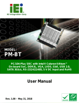
Figure 1-1: IMB-H810-i2
The IMB-H810-i2 is a microATX motherboard. It accepts a Socket LGA1150 Intel® Core™
i7, Core™ i5, Core™ i3, Pentium® or Celeron® processor and supports two 240-pin
1333/1066 MHz dual-channel DDR3 DIMM modules up to 16.0 GB maximum.
The IMB-H810-i2 features Intelligent Platform Management Interface (IPMI) that helps
lower the overall costs of server management by enabling users to maximize IT resource,
save time and manage multiple systems. The IMB-H810-i2 supports IPMI 2.0 through the
optional iRIS-2400 module.
The IMB-H810-i2 includes two VGA ports for easy dual independent display setup and
one internal DisplayPort connector supporting HDMI, LVDS, VGA, DVI and DisplayPort
with up to 3840 x 2160 resolutions. Expansion and I/O include two PCI slots, one PCIe
x16 slot, one PCIe x1 slot, two USB 3.0 ports and two USB 2.0 on the rear panel, eight
USB 2.0 by pin header, four SATA 6Gb/s connectors, ten COM ports, and two
keyboard/mouse connectors.

IMB-H810-i2 microATX Motherboard
Page 3
1.2 Benefits
Some of the IMB-H810-i2 motherboard benefits include:
Powerful graphics with multiple monitors
Staying connected with both wired LAN connections
Speedy running of multiple programs and applications
1.3 Features
Some of the IMB-H810-i2 motherboard features are listed below:
microATX form factor
RoHS compliant
LGA1150 Intel® Core™ i7, Core™ i5, Core™ i3, Pentium® or Celeron®
processor supported
Intel® H81 Chipset
Two 240-pin 1333/1066 MHz dual-channel DDR3 DIMMs with up to 16.0 GB
memory
Two VGA ports for easy dual independent display setup
Internal DisplayPort (iDP) interface supports HDMI, LVDS, VGA, DVI and
DisplayPort with up to 3840 x 2160 resolutions
Supports IPMI 2.0 via IEI iRIS-2400 module
Two Intel® PCIe GbE connectors
Four SATA 6Gb/s connectors
Two PCI card expansion slots
One PCIe x16 card expansion slot
One PCIe x1 card expansion slot
Multiple USB 3.0 and USB 2.0 ports
Ten serial ports
High Definition Audio

IMB-H810-i2 microATX Motherboard
Page 4
1.4 Connectors
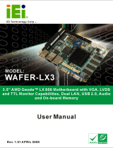
The connectors on the IMB-H810-i2 are shown in the figure below.
Figure 1-2: Connectors
/