Page is loading ...

PM-BT SBC
Page i
User Manual
MODEL:
PM-BT
PC/104-Plus SBC with Intel® Celeron®/Atom™
On-board SoC, DDR3L, VGA, LVDS, GbE, USB 2.0,
SATA 3Gb/s, RS-232/422/485, 5 V DC Input and RoHS
Rev. 1.00 – May 31, 2018

PM-BT SBC
Page ii
Revision
Date Version Changes
May 31, 2018
1.00 Initial release

PM-BT SBC
Page iii
Copyright
COPYRIGHT NOTICE
The information in this document is subject to change without prior notice in order to
improve reliability, design and function and does not represent a commitment on the part
of the manufacturer.
In no event will the manufacturer be liable for direct, indirect, special, incidental, or
consequential damages arising out of the use or inability to use the product or
documentation, even if advised of the possibility of such damages.
This document contains proprietary information protected by copyright. All rights are
reserved. No part of this manual may be reproduced by any mechanical, electronic, or
other means in any form without prior written permission of the manufacturer.
TRADEMARKS
All registered trademarks and product names mentioned herein are used for identification
purposes only and may be trademarks and/or registered trademarks of their respective
owners.

PM-BT SBC
Page iv
Manual Conventions
WARNING
Warnings appear where overlooked details may cause damage to the
equipment or result in personal injury. Warnings should be taken
seriously.
CAUTION
Cautionary messages should be heeded to help reduce the chance of
losing data or damaging the product.
NOTE
These messages inform the reader of essential but non-critical
information. These messages should be read carefully as any directions
or instructions contained therein can help avoid making mistakes.

PM-BT SBC
Page v
Table of Contents
1 INTRODUCTION .......................................................................................................... 1
1.1 INTRODUCTION ........................................................................................................... 2
1.2 MODEL VARIATIONS ................................................................................................... 2
1.3 FEATURES ................................................................................................................... 3
1.4 CONNECTORS ............................................................................................................. 4
1.5 DIMENSIONS ............................................................................................................... 5
1.6 DATA FLOW ................................................................................................................ 6
1.7 TECHNICAL SPECIFICATIONS ...................................................................................... 7
2 PACKING LIST ........................................................................................................... 10
2.1 ANTI-STATIC PRECAUTIONS ....................................................................................... 11
2.2 UNPACKING PRECAUTIONS ........................................................................................ 11
2.3 PACKING LIST ........................................................................................................... 12
2.4 OPTIONAL ITEMS ...................................................................................................... 13
3 CONNECTORS ........................................................................................................... 14
3.1 PERIPHERAL INTERFACE CONNECTORS ..................................................................... 15
3.1.1 PM-BT Layout .................................................................................................. 15
3.1.1 Peripheral Interface Connectors ..................................................................... 16
3.2 INTERNAL PERIPHERAL CONNECTORS ...................................................................... 17
3.2.1 Battery Connector ............................................................................................ 17
3.2.1 Buzzer Connector ............................................................................................. 18
3.2.2 DDR3L SO-DIMM Socket ................................................................................ 19
3.2.3 Digital I/O Connector ...................................................................................... 20
3.2.4 Front Panel Connector .................................................................................... 21
3.2.1 LAN Connector ................................................................................................ 22
3.2.1 LVDS LCD Connector ..................................................................................... 23
3.2.2 LVDS Backlight Inverter Connector ................................................................ 24
3.2.1 PC/104-Plus Connector, ISA ............................................................................ 25
3.2.1 PC/104-Plus Connector, PCI ........................................................................... 26

PM-BT SBC
Page vi
3.2.1 PC/104-Plus Power Connector ........................................................................ 28
3.2.2 PCIe Mini Slot .................................................................................................. 29
3.2.1 Power Input Connector .................................................................................... 31
3.2.2 RS-232/422/485 Serial Port Connectors ......................................................... 32
3.2.3 SATA 3Gb/s Drive Connector .......................................................................... 34
3.2.1 SATA Power Connector .................................................................................... 35
3.2.2 SPI Flash Connector ........................................................................................ 36
3.2.3 USB 2.0 Connectors ......................................................................................... 37
3.2.1 VGA Connector ................................................................................................ 38
4 INSTALLATION ......................................................................................................... 39
4.1 ANTI-STATIC PRECAUTIONS ...................................................................................... 40
4.2 INSTALLATION CONSIDERATIONS .............................................................................. 40
4.3 SO-DIMM INSTALLATION ....................................................................................... 42
4.4 FULL-SIZE PCIE MINI CARD INSTALLATION ............................................................. 43
4.5 SYSTEM CONFIGURATION ......................................................................................... 44
4.5.1 AT/ATX Power Mode Setting ........................................................................... 44
4.5.1 LVDS Panel Resolution Select Switch ............................................................. 45
4.5.1 LVDS Voltage Selection ................................................................................... 46
4.5.2 PCI Voltage Setup ............................................................................................ 47
4.6 AVAILABLE DRIVERS ................................................................................................ 48
4.6.1 Driver Download ............................................................................................. 48
4.7 OS INSTALLATION .................................................................................................... 50
5 BIOS .............................................................................................................................. 51
5.1 INTRODUCTION ......................................................................................................... 52
5.1.1 Starting Setup ................................................................................................... 52
5.1.2 Using Setup ...................................................................................................... 52
5.1.3 Getting Help ..................................................................................................... 53
5.1.4 Unable to Reboot after Configuration Changes .............................................. 53
5.1.5 BIOS Menu Bar ................................................................................................ 53
5.2 MAIN ........................................................................................................................ 54
5.3 ADVANCED ............................................................................................................... 55
5.3.1 Trusted Computing ........................................................................................... 56
5.3.2 ACPI Settings ................................................................................................... 57

PM-BT SBC
Page vii
5.3.3 F81866 Super IO Configuration ...................................................................... 58
5.3.3.1 Serial Port n Configuration ....................................................................... 58
5.3.4 F81866 H/W Monitor ....................................................................................... 61
5.3.5 RTC Wake Settings ........................................................................................... 62
5.3.6 Serial Port Console Redirection ...................................................................... 63
5.3.7 iEi Feature ....................................................................................................... 66
5.3.8 CPU Configuration .......................................................................................... 67
5.3.9 IDE Configuration ............................................................................................ 68
5.3.10 USB Configuration ......................................................................................... 69
5.4 CHIPSET ................................................................................................................... 70
5.4.1 North Bridge .................................................................................................... 71
5.4.1.1 Intel IGD Configuration ............................................................................ 72
5.4.2 South Bridge ..................................................................................................... 74
5.4.2.1 PCI Express Configuration ....................................................................... 75
5.5 SECURITY ................................................................................................................. 76
5.6 BOOT ........................................................................................................................ 77
5.7 SAVE & EXIT ............................................................................................................ 79
A REGULATORY COMPLIANCE .............................................................................. 81
B PRODUCT DISPOSAL .............................................................................................. 83
C BIOS OPTIONS .......................................................................................................... 85
D DIGITAL I/O INTERFACE ....................................................................................... 88
D.1 INTRODUCTION ........................................................................................................ 89
D.2 ASSEMBLY LANGUAGE SAMPLE 1 ............................................................................ 90
D.3 ASSEMBLY LANGUAGE SAMPLE 2 ............................................................................ 90
E WATCHDOG TIMER ................................................................................................. 91
F HAZARDOUS MATERIALS DISCLOSURE .......................................................... 94

PM-BT SBC
Page viii
List of Figures
Figure 1-1: PM-BT ........................................................................................................................... 2
Figure 1-2: Connectors .................................................................................................................. 4
Figure 1-3: PM-BT Dimensions (mm) ............................................................................................ 5
Figure 1-4: Data Flow Diagram ...................................................................................................... 6
Figure 3-1: Peripheral Interface Connectors (Front Side) ........................................................ 15
Figure 3-2: Peripheral Interface Connectors (Solder Side) ...................................................... 15
Figure 3-3: Battery Connector Location ..................................................................................... 18
Figure 3-4: Buzzer Connector Location ..................................................................................... 19
Figure 3-5: DDR3L SO-DIMM Socket Locations ........................................................................ 19
Figure 3-6: Digital I/O Connector Location ................................................................................ 20
Figure 3-7: Front Panel Connector Location ............................................................................. 21
Figure 3-8: LAN Connector Location .......................................................................................... 22
Figure 3-9: LAN Cable .................................................................................................................. 22
Figure 3-10: LVDS Connector Location...................................................................................... 23
Figure 3-11: Backlight Inverter Connector Location ................................................................. 24
Figure 3-12: PC/104 Slot Location .............................................................................................. 25
Figure 3-13: PCI-104 Connector Location .................................................................................. 27
Figure 3-14: PC/104-Plus Power Connector Pinouts ................................................................ 28
Figure 3-15: PCIe Mini Slot Location .......................................................................................... 29
Figure 3-16: Power Connector Location .................................................................................... 31
Figure 3-17: RS-232/422/485 Serial Port Connector Locations ................................................ 32
Figure 3-18: SATA 3Gb/s Drive Connector Location ................................................................ 34
Figure 3-19: SATA Power Connector Location ......................................................................... 35
Figure 3-20: SPI Flash Connector Location ............................................................................... 36
Figure 3-21: USB 2.0 Connector Locations ............................................................................... 37
Figure 3-22: VGA Connector Location ....................................................................................... 38
Figure 3-23: VGA Cable ................................................................................................................ 38
Figure 4-1: SO-DIMM Installation ................................................................................................ 42
Figure 4-2: Removing the Retention Screw ............................................................................... 43
Figure 4-3: Inserting the Full-size PCIe Mini Card into the Slot at an Angle .......................... 43

PM-BT SBC
Page ix
Figure 4-4: Securing the Full-size PCIe Mini Card .................................................................... 44
Figure 4-5: AT/ATX Power Mode Switch Location .................................................................... 44
Figure 4-6: LVDS Panel Resolution Select Switch Location .................................................... 45
Figure 4-7: LVDS Voltage Selection Jumper Locations ........................................................... 46
Figure 4-8: PCI Voltage Jumper Location .................................................................................. 47
Figure 4-9: IEI Resource Download Center ................................................................................ 48
Figure 4-10: BIOS Option–OS Selection .................................................................................... 50

PM-BT SBC
Page x
List of Tables
Table 1-1: Model Variations ........................................................................................................... 2
Table 1-2: PM-BT Specifications ................................................................................................... 8
Table 2-1: Packing List ................................................................................................................. 13
Table 2-2: Optional Items ............................................................................................................. 13
Table 3-1: Peripheral Interface Connectors ............................................................................... 16
Table 3-2: Battery Connector Pinouts ........................................................................................ 18
Table 3-3: Buzzer Connector Pinouts ......................................................................................... 19
Table 3-4: Digital I/O Connector Pinouts .................................................................................... 20
Table 3-5: Front Panel Connector Pinouts ................................................................................. 21
Table 3-6: LAN Connector Pinouts ............................................................................................. 22
Table 3-7: LVDS Connector Pinouts ........................................................................................... 23
Table 3-8: Backlight Inverter Connector Pinouts ...................................................................... 24
Table 3-9: PC/104 Slot Connector Pinouts ................................................................................. 26
Table 3-10: PCI-104 Connector Pinouts ..................................................................................... 28
Table 3-11: PC/104-Plus Power Connector Pinouts .................................................................. 29
Table 3-12: PCIe Mini Slot Pinouts .............................................................................................. 30
Table 3-13: Power Connector Pinouts ........................................................................................ 31
Table 3-14: RS-232 Serial Port Connector Pinouts ................................................................... 32
Table 3-15: DB-9 RS-232/422/485 Pinouts .................................................................................. 33
Table 3-16: SATA 3Gb/s Drive Connector Pinouts .................................................................... 34
Table 3-17: SATA Power Connector Pinouts ............................................................................. 35
Table 3-18: SPI Flash Connector Pinouts .................................................................................. 36
Table 3-19: USB 2.0 Connector Pinouts ..................................................................................... 37
Table 3-20: VGA Connector Pinouts ........................................................................................... 38
Table 4-1: AT/ATX Power Mode Switch Settings ....................................................................... 45
Table 4-2: LVDS Panel Resolution Selection ............................................................................. 45
Table 4-3: LVDS Voltage Selection Jumper Settings ................................................................ 46
Table 4-4: PCI Voltage Jumper Settings..................................................................................... 47
Table 5-1: BIOS Navigation Keys ................................................................................................ 53

PM-BT SBC
Page xi
BIOS Menus
BIOS Menu 1: Main ....................................................................................................................... 54
BIOS Menu 2: Advanced .............................................................................................................. 55
BIOS Menu 3: Trusted Computing .............................................................................................. 56
BIOS Menu 4: ACPI Configuration .............................................................................................. 57
BIOS Menu 5: F81866 Super IO Configuration .......................................................................... 58
BIOS Menu 6: Serial Port n Configuration Menu ....................................................................... 58
BIOS Menu 7: F81866 H/W Monitor ............................................................................................. 61
BIOS Menu 8: RTC Wake Settings .............................................................................................. 62
BIOS Menu 9: Serial Port Console Redirection ......................................................................... 63
BIOS Menu 10: iEi Feature ........................................................................................................... 66
BIOS Menu 11: CPU Configuration ............................................................................................. 67
BIOS Menu 12: IDE Configuration ............................................................................................... 68
BIOS Menu 13: USB Configuration ............................................................................................. 69
BIOS Menu 14: Chipset ................................................................................................................ 71
BIOS Menu 15: North Bridge ....................................................................................................... 71
BIOS Menu 16: Intel IGD Configuration ...................................................................................... 72
BIOS Menu 17: South Bridge ....................................................................................................... 74
BIOS Menu 18: PCI Express Configuration ............................................................................... 75
BIOS Menu 19: Security ............................................................................................................... 76
BIOS Menu 20: Boot ..................................................................................................................... 77
BIOS Menu 21: Save & Exit .......................................................................................................... 79


PM-BT SBC
Page 1
Chapter
1
1 Introduction

PM-BT SBC
Page 2
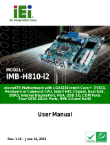
1.1 Introduction
Figure 1-1: PM-BT
The PC/104-Plus form factor PM-BT is a highly integrated embedded computer
specifically optimized for multi-media applications requiring minimum installation space.
The PM-BT is particularly suitable for low power and fan-less applications. The PM-BT
supports a full range of functions for an industrial computer in a space-saving 96 mm x
90 mm profile. The PM-BT is equipped with an on-board low-power consumption and high
performance 22nm Intel® Celeron® or Atom™ processor. It also supports a single 204-pin
1333/1066 MHz DDR3L SO-DIMM (up to 8 GB).
1.2 Model Variations
The model variations for the PM-BT series are listed in Table 1-1.
Model On-board SoC Operating Temp.
PM-BT-J19001
Intel® Celeron® processor J1900
(2 GHz, quad-core, 2 MB cache, TDP=10 W)
-20ºC ~ 60ºC
PM-BT-N28071
Intel® Celeron® processor N2807
(1.58 GHz, dual-core, 2 MB cache, TDP=4.5 W)
-20ºC ~ 60ºC
PM-BT-E38451W2*
Intel® Atom™ processor E3845
(1.91 GHz, quad-core, 2 MB cache, TDP=10 W)
-40ºC ~ 85ºC
PM-BT-E38251W2*
Intel® Atom™ processor E3825
(1.33 GHz, dual-core, 1 MB cache, TDP=6 W)
-40ºC ~ 85ºC
*Production by order, MOQ 100 pcs/lot
Table 1-1: Model Variations

PM-BT SBC
Page 3
1.3 Features
Some of the PM-BT motherboard features are listed below:
PC/104-Plus (ISA and PCI signal) function support
5V DC input solution
On-board 22nm Intel® Atom™ or Celeron® processor
One 204-pin 1333/1066 MHz single-channel DDR3L SDRAM SO-DIMM slot
supports up to 8 GB of memory (for J1900, E3845 and E3825 SKUs)
or
One 204-pin 1333/1066 MHz single-channel DDR3L SDRAM SO-DIMM slot
supports up to 4 GB of memory (for N2807 SKU)
VGA and LVDS interfaces for dual independent display
One GbE connector
One SATA 3Gb/s connector with 5 V SATA power connector
One full-size PCIe Mini card expansion slot
Three USB 2.0 ports
Two RS-232/422/485 serial ports
On-board SSD (optional)
RoHS compliant

PM-BT SBC
Page 4
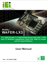
1.4 Connectors
The connectors on the PM-BT are shown in the figure below.
Figure 1-2: Connectors

PM-BT SBC
Page 5
1.5 Dimensions
The main dimensions of the PM-BT are shown in the diagram below.
Figure 1-3: PM-BT Dimensions (mm)


PM-BT SBC
Page 7
1.7 Technical Specifications
The PM-BT technical specifications are listed below.
Specification/Model PM-BT
Form Factor
PC/104-Plus
SoC
Standard
o Intel® Celeron® processor J1900
(2 GHz, quad-core, 2 MB cache, TDP=10 W)
o Intel® Celeron® processor N2807
(1.58 GHz, dual-core, 2 MB cache, TDP=4.5 W)
By request (MOQ 100)
o Intel® Atom™ processor E3845
(1.91 GHz, quad-core, 2 MB cache, TDP=10 W)
o Intel® Atom™ processor E3825
(1.33 GHz, dual-core, 1 MB cache, TDP=6 W)
Memory
For J1900, E3845 and E3825 SKUs:
One 204-pin 1333/1066 MHz single-channel DDR3L SDRAM
SO-DIMM slot supports up to 8 GB of memory
For N2807 SKU:
One 204-pin 1333/1066 MHz single-channel DDR3L SDRAM
SO-DIMM slot supports up to 4 GB of memory
Graphics Engine
Intel® HD Graphics Gen7 with 4 execution units, supporting DirectX
11.1, OpenCL 1.2 and OpenGL 4.2
Display Output
Supports dual independent display
One VGA (up to 2560x1600@60Hz)
One 18-bit/24-bit single-channel LVDS
Ethernet Controllers
Intel® I210 PCIe controller
BIOS
UEFI BIOS
Super I/O Controller
Fintek F81866
Watchdog Timer
Software programmable supports 1~255 sec. system reset

PM-BT SBC
Page 8
Expansions
One full-size PCIe Mini card slot (supports mSATA)
One PC/104-Plus (ISA + PCI)
* The ISA function is limited. Please refer to page 8 for details.
Storage
On-board SSD (optional)
I/O Interface Connectors
Digital I/O
8-bit digital I/O
Ethernet
One GbE port
Front Panel
One 10-pin header (power LED, HDD LED, power button and reset
button)
Serial ATA
One SATA 3Gb/s connector with 5 V SATA power connector
Serial Ports
Two RS-232/422/485 via internal 10-pin headers
USB 2.0
Three USB 2.0 ports via internal pin headers
Environmental and Power Specifications
Power Supply
5 V DC input
12 V for fan, LVDS and PC/104-Plus
3 V / 5 V jumper for add-in modules
Support AT/ATX mode
ErP/EuP Compliant
Power Consumption
5 V @ 1.70 A (2 GHz Intel® Celeron® processor J1900 with one 8 GB
1333 MHz DDR3L memory)
Operating
Temperature
-20ºC ~ 60ºC (for J1900/N2807 SKUs)
-40ºC ~ 85ºC (for E38xx SKUs)
Storage Temperature
-40ºC ~ 85ºC
Operating Humidity
5% ~ 95% (non-condensing)
Safety
CE, FCC
Physical Specifications
Dimensions
96 mm x 90 mm
Weight (GW/NW)
500 g / 120 g
Table 1-2: PM-BT Specifications
/