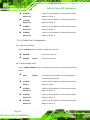
IEI Technology IMB-H612 User manual
- Category
- Motherboards
- Type
- User manual


IMB-H612 Micro-ATX Motherboard
Page iii
Copyright
COPYRIGHT NOTICE
The information in this document is subject to change without prior notice in order to
improve reliability, design and function and does not represent a commitment on the part
of the manufacturer.
In no event will the manufacturer be liable for direct, indirect, special, incidental, or
consequential damages arising out of the use or inability to use the product or
documentation, even if advised of the possibility of such damages.
This document contains proprietary information protected by copyright. All rights are
reserved. No part of this manual may be reproduced by any mechanical, electronic, or
other means in any form without prior written permission of the manufacturer.
TRADEMARKS
All registered trademarks and product names mentioned herein are used for identification
purposes only and may be trademarks and/or registered trademarks of their respective
owners.

IMB-H612 Micro-ATX Motherboard
Page iv
Table of Contents
1 INTRODUCTION .......................................................................................................... 1
1.1 INTRODUCTION ........................................................................................................... 2
1.2 MODEL VARIATIONS ................................................................................................... 2
1.3 BENEFITS ................................................................................................................... 3
1.4 FEATURES ................................................................................................................... 3
1.5 CONNECTORS ............................................................................................................. 4
1.6 DIMENSIONS ............................................................................................................... 5
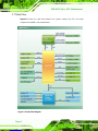
1.7 DATA FLOW ................................................................................................................ 6
1.8 TECHNICAL SPECIFICATIONS ...................................................................................... 7
2 PACKING LIST ............................................................................................................. 9
2.1 ANTI-STATIC PRECAUTIONS ...................................................................................... 10
2.2 UNPACKING PRECAUTIONS ....................................................................................... 10
2.3 PACKING LIST ............................................................................................................ 11
2.4 OPTIONAL ITEMS ...................................................................................................... 12
3 CONNECTORS ........................................................................................................... 14
3.1 PERIPHERAL INTERFACE CONNECTORS ..................................................................... 15
3.1.1 IMB-H612 Layout ............................................................................................ 15
3.1.2 Peripheral Interface Connectors ..................................................................... 16
3.1.3 External Interface Panel Connectors ............................................................... 17
3.2 INTERNAL PERIPHERAL CONNECTORS ...................................................................... 17
3.2.1 ATX Power Connector ..................................................................................... 17
3.2.2 Battery Connector ............................................................................................ 18
3.2.3 CPU Fan Connector ........................................................................................ 19
3.2.4 CPU Power Connector .................................................................................... 20
3.2.5 DDR3 DIMM Slots ........................................................................................... 21
3.2.6 Digital I/O Connector ...................................................................................... 22
3.2.7 Front Panel Audio Connector .......................................................................... 23
3.2.8 Front Panel Connector .................................................................................... 24
3.2.9 I2C Connector .................................................................................................. 25

IMB-H612 Micro-ATX Motherboard
Page v
3.2.10 PCI Slot .......................................................................................................... 26
3.2.11 PCIe x1 Slots .................................................................................................. 27
3.2.12 SATA 3Gb/s Drive Connectors ....................................................................... 28
3.2.13 Serial Port Connector, RS-422/485 ................................................................ 29
3.2.14 Serial Port Connectors, RS-232 ..................................................................... 30
3.2.15 SMBus Connector .......................................................................................... 32
3.2.16 SPI Connector ................................................................................................ 33
3.2.17 System Fan Connector ................................................................................... 34
3.2.18 TPM Connector .............................................................................................. 35
3.2.19 USB Connectors ............................................................................................. 36
3.3 EXTERNAL PERIPHERAL INTERFACE CONNECTOR PANEL ......................................... 38
3.3.1 Audio Connector .............................................................................................. 38
3.3.2 Ethernet and USB Connectors ......................................................................... 40
3.3.3 Keyboard/Mouse Connector ............................................................................ 41
3.3.4 RS-232 Serial Port Connectors ........................................................................ 42
3.3.5 VGA Connectors .............................................................................................. 42
4 INSTALLATION ......................................................................................................... 44
4.1 ANTI-STATIC PRECAUTIONS ...................................................................................... 45
4.2 INSTALLATION CONSIDERATIONS .............................................................................. 45
4.3 BASIC INSTALLATION ............................................................................................... 47
4.3.1 Socket LGA1155 CPU Installation .................................................................. 47
4.3.2 Cooling Kit Installation ................................................................................... 50
4.3.3 DIMM Installation ........................................................................................... 52
4.4 JUMPER SETTINGS .................................................................................................... 53
4.4.1 AT/ATX Power Select Jumper .......................................................................... 53
4.4.2 Clear CMOS Jumper ........................................................................................ 54
4.4.3 USB Power Select Jumpers .............................................................................. 55
4.5 INTERNAL PERIPHERAL DEVICE CONNECTIONS ........................................................ 56
4.5.1 SATA Drive Connection ................................................................................... 56
4.6 EXTERNAL PERIPHERAL INTERFACE CONNECTION ................................................... 58
4.6.1 Audio Connection ............................................................................................. 58
4.6.2 LAN Connection ............................................................................................... 59
4.6.3 PS/2 Keyboard and Mouse Connection ........................................................... 60
4.6.4 Serial Device Connection ................................................................................ 61

IMB-H612 Micro-ATX Motherboard
Page vi
4.6.5 USB Connection ............................................................................................... 62
4.6.6 VGA Monitor Connection ................................................................................ 63
5 BIOS .............................................................................................................................. 65
5.1 INTRODUCTION ......................................................................................................... 66
5.1.1 Starting Setup ................................................................................................... 66
5.1.2 Using Setup ...................................................................................................... 66
5.1.3 Getting Help ..................................................................................................... 67
5.1.4 Unable to Reboot after Configuration Changes .............................................. 67
5.1.5 BIOS Menu Bar ................................................................................................ 67
5.2 MAIN ........................................................................................................................ 68
5.3 ADVANCED ............................................................................................................... 69
5.3.1 ACPI Settings ................................................................................................... 70
5.3.2 Trusted Computing ........................................................................................... 71
5.3.3 CPU Configuration .......................................................................................... 72
5.3.3.1 CPU Information ....................................................................................... 73
5.3.4 SATA Configuration ......................................................................................... 74
5.3.5 Intel TXT(LT) Configuration ............................................................................ 75
5.3.6 USB Configuration ........................................................................................... 76
5.3.7 Super IO Configuration ................................................................................... 78
5.3.7.1 Serial Port n Configuration ....................................................................... 79
5.3.8 H/W Monitor .................................................................................................... 84
5.3.8.1 FAN 1 Configuration ................................................................................ 86
5.3.8.2 FAN 2 Configuration ................................................................................ 87
5.3.9 Secondary Super IO Configuration ................................................................. 89
5.3.9.1 Serial Port 7 Configuration ....................................................................... 90
5.3.9.2 Serial Port 8 Configuration ....................................................................... 91
5.3.9.3 Serial Port 9 Configuration ....................................................................... 92
5.3.9.4 Serial Port 10 Configuration ..................................................................... 93
5.3.10 Serial Port Console Redirection .................................................................... 94
5.3.11 IEI Feature ..................................................................................................... 96
5.4 CHIPSET ................................................................................................................... 97
5.4.1 Northbridge Configuration .............................................................................. 98
5.4.2 Southbridge Configuration ............................................................................ 100
5.4.3 Integrated Graphics ....................................................................................... 103

IMB-H612 Micro-ATX Motherboard
Page vii
5.4.4 ME Subsystem ................................................................................................ 105
5.5 BOOT ...................................................................................................................... 106
5.6 SECURITY ............................................................................................................... 107
5.7 SAVE & EXIT .......................................................................................................... 108
6 SOFTWARE DRIVERS ............................................................................................. 110
6.1 AVAILABLE SOFTWARE DRIVERS ............................................................................. 111
6.2 SOFTWARE INSTALLATION ....................................................................................... 111
6.3 CHIPSET DRIVER INSTALLATION .............................................................................. 113
6.4 GRAPHICS DRIVER INSTALLATION ........................................................................... 117
6.5 LAN DRIVER INSTALLATION ................................................................................... 119
6.6 AUDIO DRIVER INSTALLATION ............................................................................... 122
A BIOS OPTIONS ........................................................................................................ 124
B ONE KEY RECOVERY ........................................................................................... 128
B.1 ONE KEY RECOVERY INTRODUCTION .................................................................... 129
B.1.1 System Requirement ....................................................................................... 130
B.1.2 Supported Operating System ......................................................................... 131
B.2 SETUP PROCEDURE FOR WINDOWS ........................................................................ 132
B.2.1 Hardware and BIOS Setup ............................................................................ 133
B.2.2 Create Partitions ........................................................................................... 133
B.2.3 Install Operating System, Drivers and Applications ..................................... 137
B.2.4 Building the Recovery Partition .................................................................... 138
B.2.5 Create Factory Default Image ....................................................................... 140
B.3 AUTO RECOVERY SETUP PROCEDURE .................................................................... 145
B.4 SETUP PROCEDURE FOR LINUX .............................................................................. 149
B.5 RECOVERY TOOL FUNCTIONS ................................................................................ 153
B.5.1 Factory Restore ............................................................................................. 154
B.5.2 Backup System ............................................................................................... 155
B.5.3 Restore Your Last Backup .............................................................................. 156
B.5.4 Manual ........................................................................................................... 157
B.6 RESTORE SYSTEMS FROM A LINUX SERVER THROUGH LAN .................................. 158
B.6.1 Configure DHCP Server Settings .................................................................. 159
B.6.2 Configure TFTP Settings ............................................................................... 160
B.6.3 Configure One Key Recovery Server Settings ............................................... 161

IMB-H612 Micro-ATX Motherboard
Page viii
B.6.4 Start the DHCP, TFTP and HTTP ................................................................. 162
B.6.5 Create Shared Directory ................................................................................ 162
B.6.6 Setup a Client System for Auto Recovery ...................................................... 164
B.7 OTHER INFORMATION ............................................................................................ 166
B.7.1 Using AHCI Mode or ALi M5283 / VIA VT6421A Controller ....................... 166
B.7.2 System Memory Requirement ........................................................................ 168
C TERMINOLOGY ..................................................................................................... 169
D DIGITAL I/O INTERFACE ..................................................................................... 173
D.1 INTRODUCTION ...................................................................................................... 174
D.2 DIO CONNECTOR PINOUTS ................................................................................... 174
D.3 ASSEMBLY LANGUAGE SAMPLES ........................................................................... 174
D.3.1 Enable the DIO Input Function .................................................................... 174
D.3.2 Enable the DIO Output Function .................................................................. 175
E WATCHDOG TIMER ............................................................................................... 176
F COMPATIBILITY ..................................................................................................... 179
F.1 COMPATIBLE OPERATING SYSTEMS ........................................................................ 180
F.2 COMPATIBLE PROCESSORS ...................................................................................... 180
G HAZARDOUS MATERIALS DISCLOSURE ....................................................... 181
G.1 HAZARDOUS MATERIALS DISCLOSURE TABLE FOR IPB PRODUCTS CERTIFIED AS
ROHS COMPLIANT UNDER 2002/95/EC WITHOUT MERCURY ..................................... 182

IMB-H612 Micro-ATX Motherboard
Page ix
List of Figures
Figure 1-1: IMB-H612 ...................................................................................................................... 2
Figure 1-2: Connectors .................................................................................................................. 4
Figure 1-3: IMB-H612 Dimensions (mm) ...................................................................................... 5
Figure 1-4: Data Flow Diagram ...................................................................................................... 6
Figure 3-1: Connectors and Jumpers .........................................................................................15
Figure 3-2: ATX Power Connector Location ..............................................................................18
Figure 3-3: Battery Connector Location .....................................................................................19
Figure 3-4: CPU Fan Connector Location ..................................................................................20
Figure 3-5: CPU Power Connector Location ..............................................................................21
Figure 3-6: DDR3 DIMM Slot Locations ......................................................................................22
Figure 3-7: Digital I/O Connector Location ................................................................................23
Figure 3-8: Front Panel Audio Connector Location ..................................................................24
Figure 3-9: Front Panel Connector Location .............................................................................25
Figure 3-10: I2C Connector Location ..........................................................................................26
Figure 3-11: PCI Slot Locations ..................................................................................................27
Figure 3-12: PCIe x1 Slot Locations ...........................................................................................28
Figure 3-13: SATA 3Gb/s Drive Connector Locations ..............................................................29
Figure 3-14: Serial Port Connector ( RS-422/485) Location .....................................................30
Figure 3-15: Serial Port Connector ( RS-232) Locations ..........................................................31
Figure 3-16: SMBus Connector Location ...................................................................................33
Figure 3-17: SPI Connector Location .........................................................................................34
Figure 3-18: System Fan Connector Locations .........................................................................35
Figure 3-19: TPM Connector Location ........................................................................................36
Figure 3-20: USB Connector Pinout Locations .........................................................................37
Figure 3-21: External Peripheral Interface Connector ..............................................................38
Figure 3-22: Audio Connector .....................................................................................................39
Figure 3-23: LAN Connector ........................................................................................................40
Figure 3-24: RS-232 Serial Port Connector ................................................................................42
Figure 3-25: VGA Connector .......................................................................................................43
Figure 4-1: Disengage the CPU Socket Load Lever ..................................................................48

IMB-H612 Micro-ATX Motherboard
Page x
Figure 4-2: Remove Protective Cover .........................................................................................48
Figure 4-3: Insert the Socket LGA1155 CPU ..............................................................................49
Figure 4-4: Close the Socket LGA1155 .......................................................................................50
Figure 4-5: Cooling Kits (CF-1156A-RS, CF-1156B-RS, CF-1156C-RS) ...................................50
Figure 4-6: Cooling Kit Support Bracket ....................................................................................51
Figure 4-7: DIMM Installation .......................................................................................................52
Figure 4-8: Jumper Locations .....................................................................................................53
Figure 4-9: AT/ATX Power Select Jumper Location ..................................................................54
Figure 4-10: Clear CMOS Jumper Location ...............................................................................55
Figure 4-11: USB Power Select Jumpers Location ...................................................................56
Figure 4-12: SATA Drive Cable Connection ...............................................................................57
Figure 4-13: SATA Power Drive Connection ..............................................................................58
Figure 4-14: Audio Connector .....................................................................................................59
Figure 4-15: LAN Connection ......................................................................................................60
Figure 4-16: PS/2 Keyboard/Mouse Connector .........................................................................61
Figure 4-17: Serial Device Connector .........................................................................................62
Figure 4-18: USB Connector ........................................................................................................63
Figure 4-19: VGA Connector .......................................................................................................64
Figure 6-1: Introduction Screen ................................................................................................112
Figure 6-2: Available Drivers .....................................................................................................112
Figure 6-3: Chipset Driver Screen .............................................................................................113
Figure 6-4: Chipset Driver Welcome Screen ............................................................................114
Figure 6-5: Chipset Driver License Agreement .......................................................................114
Figure 6-6: Chipset Driver Read Me File ..................................................................................115
Figure 6-7: Chipset Driver Setup Operations ..........................................................................116
Figure 6-8: Chipset Driver Installation Finish Screen .............................................................116
Figure 6-9: Graphics Driver Welcome Screen .........................................................................117
Figure 6-10: Graphics Driver License Agreement ...................................................................118
Figure 6-11: Graphics Driver Setup Operations ......................................................................118
Figure 6-12: Graphics Driver Installation Finish Screen ........................................................119
Figure 6-13: LAN Driver Welcome Screen ...............................................................................120
Figure 6-14: LAN Driver Ready to Install Screen .....................................................................120
Figure 6-15: LAN Driver Setup Status Screen .........................................................................121
Figure 6-16: LAN Driver Installation Complete ........................................................................121
Figure 6-17: Audio Driver – Extracting Files ............................................................................122

IMB-H612 Micro-ATX Motherboard
Page xi
Figure 6-18: Audio Driver Welcome Screen .............................................................................123
Figure 6-19: Audio Driver Installation .......................................................................................123
Figure 6-20: Audio Driver Installation Complete .....................................................................123
Figure B-1: IEI One Key Recovery Tool Menu .........................................................................129
Figure B-2: Launching the Recovery Tool ...............................................................................134
Figure B-3: Recovery Tool Setup Menu ...................................................................................134
Figure B-4: Command Prompt ..................................................................................................135
Figure B-5: Partition Creation Commands ...............................................................................136
Figure B-6: Launching the Recovery Tool ...............................................................................138
Figure B-7: Manual Recovery Environment for Windows ......................................................138
Figure B-8: Building the Recovery Partition ............................................................................139
Figure B-9: Press Any Key to Continue ...................................................................................139
Figure B-10: Press F3 to Boot into Recovery Mode ................................................................140
Figure B-11: Recovery Tool Menu ............................................................................................140
Figure B-12: About Symantec Ghost Window .........................................................................141
Figure B-13: Symantec Ghost Path ..........................................................................................141
Figure B-14: Select a Local Source Drive ................................................................................142
Figure B-15: Select a Source Partition from Basic Drive .......................................................142
Figure B-16: File Name to Copy Image to ................................................................................143
Figure B-17: Compress Image ...................................................................................................143
Figure B-18: Image Creation Confirmation ..............................................................................144
Figure B-19: Image Creation Complete ....................................................................................144
Figure B-20: Image Creation Complete ....................................................................................144
Figure B-21: Press Any Key to Continue .................................................................................145
Figure B-22: Auto Recovery Utility ...........................................................................................146
Figure B-23: Launching the Recovery Tool .............................................................................146
Figure B-24: Auto Recovery Environment for Windows ........................................................146
Figure B-25: Building the Auto Recovery Partition .................................................................147
Figure B-26: Factory Default Image Confirmation ..................................................................147
Figure B-27: Image Creation Complete ....................................................................................148
Figure B-28: Press any key to continue ...................................................................................148
Figure B-29: Partitions for Linux ...............................................................................................150
Figure B-30: Manual Recovery Environment for Linux ..........................................................151
Figure B-31: Access menu.lst in Linux (Text Mode) ...............................................................152
Figure B-32: Recovery Tool Menu ............................................................................................152

IMB-H612 Micro-ATX Motherboard
Page xii
Figure B-33: Recovery Tool Main Menu ...................................................................................153
Figure B-34: Restore Factory Default .......................................................................................154
Figure B-35: Recovery Complete Window ...............................................................................155
Figure B-36: Backup System .....................................................................................................155
Figure B-37: System Backup Complete Window ....................................................................156
Figure B-38: Restore Backup ....................................................................................................156
Figure B-39: Restore System Backup Complete Window ......................................................157
Figure B-40: Symantec Ghost Window ....................................................................................157

IMB-H612 Micro-ATX Motherboard
Page xiii
List of Tables
Table 1-1: Model Variations ........................................................................................................... 2
Table 1-2: IMB-H612 Specifications .............................................................................................. 8
Table 2-1: Packing List .................................................................................................................12
Table 2-2: Optional Items .............................................................................................................13
Table 3-1: Peripheral Interface Connectors ...............................................................................17
Table 3-2: Rear Panel Connectors ..............................................................................................17
Table 3-3: ATX Power Connector Pinouts ..................................................................................18
Table 3-4: CPU Fan Connector Pinouts .....................................................................................20
Table 3-5: CPU Power Connector Pinouts .................................................................................21
Table 3-6: Digital I/O Connector Pinouts ....................................................................................23
Table 3-7: Front Panel Audio Connector Pinouts .....................................................................24
Table 3-8: Front Panel Connector Pinouts .................................................................................25
Table 3-9: I2C Connector Pinouts ...............................................................................................26
Table 3-10: SATA 3Gb/s Drive Connector Pinouts ....................................................................29
Table 3-11: Serial Port Connector ( RS-422/485) Pinouts .........................................................30
Table 3-12: Serial Port Connector Pinouts (COM3, COM4, COM5) ..........................................31
Table 3-13: Serial Port Connector Pinouts (COM7-10) .............................................................32
Table 3-14: SMBus Connector Pinouts ......................................................................................33
Table 3-15: SPI Connector Pinouts .............................................................................................34
Table 3-16: System Fan Connector Pinouts ..............................................................................35
Table 3-17: TPM Connector Pinouts ...........................................................................................36
Table 3-18: USB Port Connector Pinouts (USB45) ....................................................................37
Table 3-19: USB Port Connector Pinouts (USB67) ....................................................................37
Table 3-20: USB Port Connector Pinouts (USB89) ....................................................................38
Table 3-21: Audio Connector Pinouts ........................................................................................39
Table 3-22: LAN Connector Pinouts ...........................................................................................40
Table 3-23: USB Connector Pinouts (USB01) ............................................................................41
Table 3-24: USB Connector Pinouts (USB23) ............................................................................41
Table 3-25: PS/2 Connector Pinouts ...........................................................................................41
Table 3-26: RS-232 Serial Port Connector Pinouts (COM1,COM2) ..........................................42

IMB-H612 Micro-ATX Motherboard
Page xiv
Table 3-27: VGA Connector Pinouts (VGA1,VGA2) ...................................................................43
Table 4-1: Jumpers .......................................................................................................................53
Table 4-2: AT/ATX Power Select Jumper Settings ....................................................................54
Table 4-3: Clear CMOS Jumper Settings ....................................................................................55
Table 4-4: USB Power Select Jumper Settings .........................................................................56
Table 5-1: BIOS Navigation Keys ................................................................................................67
Table 6-1: Digital I/O Connector Pinouts ..................................................................................174

IMB-H612 Micro-ATX Motherboard
Page xv
BIOS Menus
BIOS Menu 1: Main .......................................................................................................................68
BIOS Menu 2: Advanced ..............................................................................................................70
BIOS Menu 3: ACPI Configuration ..............................................................................................70
BIOS Menu 4: Trusted Computing ..............................................................................................71
BIOS Menu 5: CPU Configuration ...............................................................................................72
BIOS Menu 6: CPU Configuration ...............................................................................................73
BIOS Menu 7: SATA Configuration .............................................................................................74
BIOS Menu 8: Intel TXT(LT) Configuration .................................................................................76
BIOS Menu 9: USB Configuration ...............................................................................................76
BIOS Menu 10: Super IO Configuration ......................................................................................78
BIOS Menu 11: Serial Port n Configuration Menu .....................................................................79
BIOS Menu 12: H/W Monitor ........................................................................................................85
BIOS Menu 13: FAN 1 Configuration ..........................................................................................86
BIOS Menu 14: FAN 2 Configuration ..........................................................................................88
BIOS Menu 15: Secondary Super IO Configuration ..................................................................89
BIOS Menu 16: Serial Port Console Redirection .......................................................................95
BIOS Menu 17: IEI Feature ...........................................................................................................96
BIOS Menu 18: Chipset ................................................................................................................97
BIOS Menu 19: Northbridge Chipset Configuration ..................................................................98
BIOS Menu 20: Southbridge Chipset Configuration ...............................................................101
BIOS Menu 21: Integrated Graphics .........................................................................................104
BIOS Menu 22: ME Subsystem ..................................................................................................105
BIOS Menu 23: Boot ...................................................................................................................106
BIOS Menu 24: Security .............................................................................................................108
BIOS Menu 25: Save & Exit ........................................................................................................109
BIOS Menu 26: IEI Feature .........................................................................................................149


IMB-H612 Micro-ATX Motherboard
Page 2
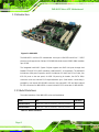
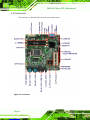
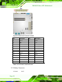
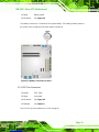
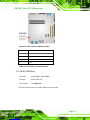
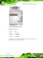
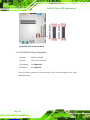
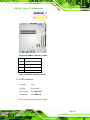
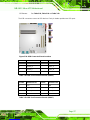
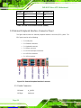
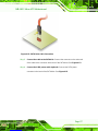
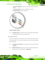
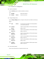
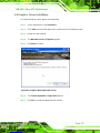
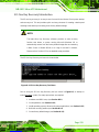
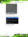
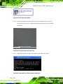
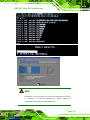
1.1 Introduction
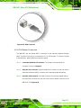
Figure 1-1: IMB-H612
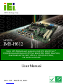
The IMB-H612 is a Micro-ATX motherboard. It accepts a LGA1155 Intel® Core™ i3/i5/i7
processor and supports two 240-pin 1333/1066 MHz dual-channel DDR3 DIMM modules
up to 16 GB.
The integrated Intel® H61 System Chipset supports two GbE LAN ports through dual
Realtek RTL8111E PCIe GbE controllers (LAN1 with ASF 2.0 supported). The IMB-H612
includes two VGA ports. Expansion and I/O include two PCI slots, two PCIe x1 slots, four
USB 2.0 ports on the rear panel, six USB 2.0 ports by pin header, four SATA 3Gb/s
connectors and one external PS/2 keyboard/mouse port. Serial device connectivity is
provided by one internal RS-422/485 connector, two external RS-232 and three internal
RS-232 connectors for IMB-H612A or seven internal RS-232 connectors for IMB-H612B.
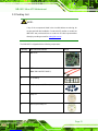
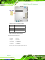
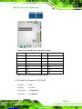
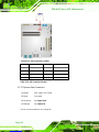
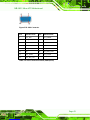
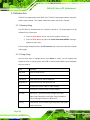
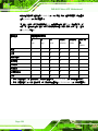
1.2 Model Variations
The model variations of the IMB-H612 series are listed below.
Models CPU Serial Ports
IMB-H612A-R10 Intel® Core™ i3/i5/i7, Pentium®, Celeron® processor Six
IMB-H612B-R10 Intel® Core™ i3/i5/i7, Pentium®, Celeron® processor Ten
Table 1-1: Model Variations

IMB-H612 Micro-ATX Motherboard
Page 3
1.3 Benefits
Some of the IMB-H612 motherboard benefits include:
Powerful graphics with multiple monitors
Staying connected with both wired LAN connections
Speedy running of multiple programs and applications
1.4 Features
Some of the IMB-H612 motherboard features are listed below:
LGA1155 Intel® Core™ i7/i5/i3 processor supported
Dual-channel 1333MHz DDR3/DDR3L (1.35V) supports up to 16GB
Intel® HD Graphics technology integrates high-performance graphics and
media processing
Supports independent display output via dual VGA
Supports legacy PCI 32-bit 33/66MHz
Supports lower power 1.35V DDR3 memory
TPM V1.2 hardware security function supported by TPM module
IEI One Key Recovery solution allows you to create rapid OS backup and
recovery


Page is loading ...
Page is loading ...
Page is loading ...
Page is loading ...
Page is loading ...
Page is loading ...
Page is loading ...
Page is loading ...
Page is loading ...
Page is loading ...
Page is loading ...
Page is loading ...
Page is loading ...
Page is loading ...
Page is loading ...
Page is loading ...
Page is loading ...
Page is loading ...
Page is loading ...
Page is loading ...
Page is loading ...
Page is loading ...
Page is loading ...
Page is loading ...
Page is loading ...
Page is loading ...
Page is loading ...
Page is loading ...
Page is loading ...
Page is loading ...
Page is loading ...
Page is loading ...
Page is loading ...
Page is loading ...
Page is loading ...
Page is loading ...
Page is loading ...
Page is loading ...
Page is loading ...
Page is loading ...
Page is loading ...
Page is loading ...
Page is loading ...
Page is loading ...
Page is loading ...
Page is loading ...
Page is loading ...
Page is loading ...
Page is loading ...
Page is loading ...
Page is loading ...
Page is loading ...
Page is loading ...
Page is loading ...
Page is loading ...
Page is loading ...
Page is loading ...
Page is loading ...
Page is loading ...
Page is loading ...
Page is loading ...
Page is loading ...
Page is loading ...
Page is loading ...
Page is loading ...
Page is loading ...
Page is loading ...
Page is loading ...
Page is loading ...
Page is loading ...
Page is loading ...
Page is loading ...
Page is loading ...
Page is loading ...
Page is loading ...
Page is loading ...
Page is loading ...
Page is loading ...
Page is loading ...
Page is loading ...
Page is loading ...
Page is loading ...
Page is loading ...
Page is loading ...
Page is loading ...
Page is loading ...
Page is loading ...
Page is loading ...
Page is loading ...
Page is loading ...
Page is loading ...
Page is loading ...
Page is loading ...
Page is loading ...
Page is loading ...
Page is loading ...
Page is loading ...
Page is loading ...
Page is loading ...
Page is loading ...
Page is loading ...
Page is loading ...
Page is loading ...
Page is loading ...
Page is loading ...
Page is loading ...
Page is loading ...
Page is loading ...
Page is loading ...
Page is loading ...
Page is loading ...
Page is loading ...
Page is loading ...
Page is loading ...
Page is loading ...
Page is loading ...
Page is loading ...
Page is loading ...
Page is loading ...
Page is loading ...
Page is loading ...
Page is loading ...
Page is loading ...
Page is loading ...
Page is loading ...
Page is loading ...
Page is loading ...
Page is loading ...
Page is loading ...
Page is loading ...
Page is loading ...
Page is loading ...
Page is loading ...
Page is loading ...
Page is loading ...
Page is loading ...
Page is loading ...
Page is loading ...
Page is loading ...
Page is loading ...
Page is loading ...
Page is loading ...
Page is loading ...
Page is loading ...
Page is loading ...
Page is loading ...
Page is loading ...
Page is loading ...
Page is loading ...
Page is loading ...
Page is loading ...
Page is loading ...
Page is loading ...
Page is loading ...
Page is loading ...
Page is loading ...
Page is loading ...
Page is loading ...
Page is loading ...
Page is loading ...
Page is loading ...
Page is loading ...
Page is loading ...
Page is loading ...
Page is loading ...
Page is loading ...
Page is loading ...
Page is loading ...
Page is loading ...
Page is loading ...
Page is loading ...
Page is loading ...
Page is loading ...
Page is loading ...
Page is loading ...
Page is loading ...
Page is loading ...
Page is loading ...
Page is loading ...
-
 1
1
-
 2
2
-
 3
3
-
 4
4
-
 5
5
-
 6
6
-
 7
7
-
 8
8
-
 9
9
-
 10
10
-
 11
11
-
 12
12
-
 13
13
-
 14
14
-
 15
15
-
 16
16
-
 17
17
-
 18
18
-
 19
19
-
 20
20
-
 21
21
-
 22
22
-
 23
23
-
 24
24
-
 25
25
-
 26
26
-
 27
27
-
 28
28
-
 29
29
-
 30
30
-
 31
31
-
 32
32
-
 33
33
-
 34
34
-
 35
35
-
 36
36
-
 37
37
-
 38
38
-
 39
39
-
 40
40
-
 41
41
-
 42
42
-
 43
43
-
 44
44
-
 45
45
-
 46
46
-
 47
47
-
 48
48
-
 49
49
-
 50
50
-
 51
51
-
 52
52
-
 53
53
-
 54
54
-
 55
55
-
 56
56
-
 57
57
-
 58
58
-
 59
59
-
 60
60
-
 61
61
-
 62
62
-
 63
63
-
 64
64
-
 65
65
-
 66
66
-
 67
67
-
 68
68
-
 69
69
-
 70
70
-
 71
71
-
 72
72
-
 73
73
-
 74
74
-
 75
75
-
 76
76
-
 77
77
-
 78
78
-
 79
79
-
 80
80
-
 81
81
-
 82
82
-
 83
83
-
 84
84
-
 85
85
-
 86
86
-
 87
87
-
 88
88
-
 89
89
-
 90
90
-
 91
91
-
 92
92
-
 93
93
-
 94
94
-
 95
95
-
 96
96
-
 97
97
-
 98
98
-
 99
99
-
 100
100
-
 101
101
-
 102
102
-
 103
103
-
 104
104
-
 105
105
-
 106
106
-
 107
107
-
 108
108
-
 109
109
-
 110
110
-
 111
111
-
 112
112
-
 113
113
-
 114
114
-
 115
115
-
 116
116
-
 117
117
-
 118
118
-
 119
119
-
 120
120
-
 121
121
-
 122
122
-
 123
123
-
 124
124
-
 125
125
-
 126
126
-
 127
127
-
 128
128
-
 129
129
-
 130
130
-
 131
131
-
 132
132
-
 133
133
-
 134
134
-
 135
135
-
 136
136
-
 137
137
-
 138
138
-
 139
139
-
 140
140
-
 141
141
-
 142
142
-
 143
143
-
 144
144
-
 145
145
-
 146
146
-
 147
147
-
 148
148
-
 149
149
-
 150
150
-
 151
151
-
 152
152
-
 153
153
-
 154
154
-
 155
155
-
 156
156
-
 157
157
-
 158
158
-
 159
159
-
 160
160
-
 161
161
-
 162
162
-
 163
163
-
 164
164
-
 165
165
-
 166
166
-
 167
167
-
 168
168
-
 169
169
-
 170
170
-
 171
171
-
 172
172
-
 173
173
-
 174
174
-
 175
175
-
 176
176
-
 177
177
-
 178
178
-
 179
179
-
 180
180
-
 181
181
-
 182
182
-
 183
183
-
 184
184
-
 185
185
-
 186
186
-
 187
187
-
 188
188
-
 189
189
-
 190
190
-
 191
191
-
 192
192
-
 193
193
-
 194
194
-
 195
195
-
 196
196
-
 197
197
-
 198
198
-
 199
199


IEI Technology IMB-H612 User manual
- Category
- Motherboards
- Type
- User manual
Ask a question and I''ll find the answer in the document
Finding information in a document is now easier with AI
Related papers
-
 IEI Technology IMB-H810-i2 User manual
-
 IEI Technology KINO-DH810 User manual
-
IEI Integration IMBA-G410 User manual
-
 IEI Technology ECN-680A-H61 User manual
-
-
 IEI Technology PM-BT-E38251W2 User manual
-
-
 IEI Technology IMBA-8654 User manual
-
 IEI Technology NANO-GM45A User manual
-
 IEI Technology WAFER-LX3 User manual


Other documents
-
 Haworth e100-4400a Operating instructions
-
 Haworth 7021-7598b Operating instructions
-
 Haworth 7029-9564a Operating instructions
-
 Haworth 7029-9478a Operating instructions
-
-
-
-
ADLINK Technology IMB-M43H User manual
-
-
ASROCK IMB-161-D Owner's manual


