Page is loading ...

IMBA-8654 Motherboard
Page i

IMBA-8654 Motherboard
Page ii
Revision
MODEL IMBA-8654 Motherboard
Revision Number Description Date of Issue
1.00 Initial release April 2007

IMBA-8654 Motherboard
Page iii
Copyright
COPYRIGHT NOTICE
The information in this document is subject to change without prior notice in order to
improve reliability, design and function and does not represent a commitment on the part
of the manufacturer.
In no event will the manufacturer be liable for direct, indirect, special, incidental, or
consequential damages arising out of the use or inability to use the product or
documentation, even if advised of the possibility of such damages.
This document contains proprietary information protected by copyright. All rights are
reserved. No part of this manual may be reproduced by any mechanical, electronic, or
other means in any form without prior written permission of the manufacturer.
TRADEMARKS
IBM PC is a registered trademark of International Business Machines Corporation. INTEL
is a registered trademark of INTEL Corporation. Other product names mentioned herein
are used for identification purposes only and may be trademarks and/or registered
trademarks of their respective owners.

IMBA-8654 Motherboard
Page iv
Packing List
NOTE:
If any of the components listed in the checklist below are missing, please do not
proceed with the installation. Contact the IEI reseller or vendor you purchased the
IMBA-8654 motherboard from or contact an IEI sales representative directly. To contact
an IEI sales representative, please send an email to sales@iei.com.tw.
The items listed below should all be included in the IMBA-8654 motherboard package.
1 x IMBA-8654 Single Board Computer
1 x IDE Cable (P/N: 32200-000052-RS)
2 x RS-232 Cable (P/N: 32200-004101-RS)
1 x RS-232 Cable (P/N: 32200-029400-RS)
1 x RS-422/485 Cable (P/N: 19800-000063-RS)
2 x SATA Cable (P/N: 32000-0628000-RS)
1 x SATA Power Cable (P/N: 32100-088600-RS)
1 x I/O Shielding (P/N: 45002-0804C0-00-RS)
1 x Mini Jumper Pack (P/N: 33100-000079-RS)
1 x Utility CD (P/N: 51100-000079-RS)
1 x QIG (Quick Installation Guide) (P/N 51000-021930-RS)
Images of the above items are shown in Chapter 3.

IMBA-8654 Motherboard
Page v
Table of Contents
1 INTRODUCTION..................................................................................................... 1
1.1 IMBA-8654 OVERVIEW............................................................................................. 2
1.1.1 IMBA-8654 Features.......................................................................................... 2
1.2 IMBA-8654 OVERVIEW............................................................................................. 2
1.2.1 IMBA-8654 Overview Photo.............................................................................. 3
1.2.2 IMBA-8654 Peripheral Connectors and Jumpers ............................................. 4
1.2.3 Technical Specifications..................................................................................... 5
2 DETAILED SPECIFICATIONS ............................................................................. 7
2.1 OVERVIEW ................................................................................................................. 8
2.2 DIMENSIONS .............................................................................................................. 8
2.2.1 Board Dimensions.............................................................................................. 8
2.2.2 External Interface Panel Dimensions................................................................ 9
2.3 DATA FLOW.............................................................................................................. 10
2.4 COMPATIBLE PROCESSORS ........................................................................................11
2.4.1 CPU Overview..................................................................................................11
2.4.2 Supported Intel® Pentium® 4 Processors........................................................11
2.4.3 Supported Intel® Pentium® D Processors...................................................... 12
2.4.4 Supported Intel® Celeron® D Processors ...................................................... 12
2.5 INTEL® 865G NORTHBRIDGE CHIPSET.................................................................... 12
2.5.1 Intel® 865G Overview..................................................................................... 12
2.5.2 Intel® 865G Memory Support ......................................................................... 15
2.5.3 Intel® 865G Integrated Graphics.................................................................... 15
2.6 INTEL® ICH5 SOUTHBRIDGE CHIPSET ..................................................................... 18
2.6.1 Intel® ICH5 Overview...................................................................................... 18
2.6.2 Intel® ICH5 Audio Codec ’97 Controller......................................................... 18
2.6.3 Intel® ICH5 IDE Interface............................................................................... 19
2.6.4 Intel® ICH5 Low Pin Count (LPC) Interface................................................... 19
2.6.5 Intel® ICH5 PCI Interface ............................................................................... 20
2.6.6 Intel® ICH5 Real Time Clock........................................................................... 20
2.6.7 Intel® ICH5 SATA Controller........................................................................... 20

IMBA-8654 Motherboard
Page vi
2.6.8 Intel® ICH5 USB Controller............................................................................ 21
2.7 PCI BUS COMPONENTS............................................................................................ 21
2.7.1 PCI Bus Overview............................................................................................ 21
2.7.2 Realtek GbE interface...................................................................................... 21
2.8 LPC BUS COMPONENTS........................................................................................... 22
2.8.1 LPC Bus Overview........................................................................................... 22
2.8.2 BIOS Chipset.................................................................................................... 22
2.8.3 Super I/O chipset.............................................................................................. 22
2.8.3.1 Super I/O LPC Interface ........................................................................... 23
2.8.3.2 Super I/O 16C550 UARTs ........................................................................ 23
2.8.3.3 Super I/O Hardware Monitor.................................................................... 23
2.8.3.4 Super I/O Fan Speed Controller................................................................ 24
2.8.3.5 Super I/O Parallel Port.............................................................................. 24
2.9 ENVIRONMENTAL AND POWER SPECIFICATIONS ....................................................... 24
2.9.1 System Monitoring........................................................................................... 24
2.9.2 Operating Temperature and Temperature Control........................................... 25
2.9.3 Power Consumption......................................................................................... 26
3 UNPACKING.......................................................................................................... 27
3.1 ANTI-STATIC PRECAUTIONS...................................................................................... 28
3.2 UNPACKING.............................................................................................................. 29
3.2.1 Unpacking Precautions.................................................................................... 29
3.3 UNPACKING CHECKLIST........................................................................................... 29
3.3.1 Package Contents............................................................................................. 29
3.3.2 Optional Components ...................................................................................... 31
4 CONNECTOR PINOUTS...................................................................................... 33
4.1 PERIPHERAL INTERFACE CONNECTORS .................................................................... 34
4.1.1 IMBA-8654 Layout........................................................................................... 34
4.1.2 Peripheral Interface Connectors ..................................................................... 34
4.1.3 External Peripheral Interface Panel Connectors............................................ 36
4.2 INTERNAL PERIPHERAL CONNECTORS...................................................................... 36
4.2.1 ATX Power Supply Connector (4-pins)............................................................ 37
4.2.2 AGP Connector (66-pins) ................................................................................ 38
4.2.3 ATX Power Supply Connector (24-pins).......................................................... 41

IMBA-8654 Motherboard
Page vii
4.2.4 Audio Connector (8-pin).................................................................................. 43
4.2.5 Auxiliary Audio Connector (4-pin) .................................................................. 44
4.2.6 CD-In Connector ............................................................................................. 45
4.2.7 Compact Flash Socket...................................................................................... 46
4.2.8 Digital Input/Output (DIO) Connector............................................................ 49
4.2.9 Fan Connectors................................................................................................ 50
4.2.10 Floppy Disk Connector.................................................................................. 51
4.2.11 Front Panel Audio Connector........................................................................ 52
4.2.12 Front Panel Connector (14-pin).................................................................... 54
4.2.13 IDE Connector (40-pin)................................................................................. 56
4.2.14 Infrared Interface Connector (5-pin)............................................................. 58
4.2.15 PCI Slot.......................................................................................................... 59
4.2.16 SATA Drive Connectors ................................................................................. 63
4.2.17 Serial Port Connector (RS-232/422/485) ...................................................... 65
4.2.18 Serial Port Connector (RS-422/485) ............................................................. 66
4.2.19 SPDIF Connector........................................................................................... 67
4.2.20 USB Connectors (Internal)............................................................................ 69
4.3 EXTERNAL PERIPHERAL INTERFACE CONNECTORS .................................................. 70
4.3.1 Keyboard/Mouse Connector............................................................................ 70
4.3.2 Parallel Port Connector .................................................................................. 71
4.3.3 USB Connectors............................................................................................... 72
4.3.4 Ethernet Connector.......................................................................................... 73
4.3.5 Audio Connectors............................................................................................. 75
4.3.6 VGA Connector................................................................................................ 76
4.3.7 Serial Communications Connector.................................................................. 76
4.4 ON-BOARD JUMPERS................................................................................................ 77
5 INSTALLATION .................................................................................................... 79
5.1 ANTI-STATIC PRECAUTIONS...................................................................................... 80
5.2 INSTALLATION CONSIDERATIONS ............................................................................. 81
5.2.1 Installation Notices.......................................................................................... 81
5.2.2 Installation Checklist....................................................................................... 82
5.3 CPU, CPU COOLING KIT AND DIMM INSTALLATION ............................................. 83
5.3.1 LGA775 CPU Installation................................................................................ 83
5.3.2 LGA775 Cooling Kit Installation..................................................................... 87

IMBA-8654 Motherboard
Page viii
5.3.3 DIMM Installation........................................................................................... 89
5.4 JUMPER SETTINGS.................................................................................................... 90
5.4.1 CF Master/Slave Selection............................................................................... 91
5.4.2 Clear CMOS Jumper........................................................................................ 92
5.4.3 COM3 Mode Selection..................................................................................... 93
5.5 CHASSIS INSTALLATION ........................................................................................... 93
5.5.1 Airflow.............................................................................................................. 93
5.6 INTERNAL PERIPHERAL DEVICE CONNECTIONS........................................................ 94
5.6.1 Peripheral Device Cables................................................................................ 94
5.6.2 ATA Flat Cable Connection ............................................................................. 95
5.6.3 Dual RS-232 Cable with Slot Bracket.............................................................. 96
5.6.4 Single RS-232 Cable with Slot Bracket............................................................ 97
5.6.5 Dual RS-422/485 Cables.................................................................................. 98
5.6.6 SATA Drive Connection ................................................................................... 99
5.7 EXTERNAL PERIPHERAL INTERFACE CONNECTION................................................. 100
5.7.1 PS/2 Keyboard/Mouse Connection................................................................ 101
5.7.2 Parallel Device Connection........................................................................... 102
5.7.3 RJ-45 Ethernet Connection............................................................................ 103
5.7.4 USB Connection............................................................................................. 103
5.7.5 Audio Connection........................................................................................... 104
5.7.6 VGA Monitor Connection .............................................................................. 105
5.7.7 Serial Device Connection .............................................................................. 106
6 AMI BIOS.............................................................................................................. 109
6.1 INTRODUCTION .......................................................................................................110
6.1.1 Starting Setup..................................................................................................110
6.1.2 Using Setup.....................................................................................................110
6.1.3 Getting Help....................................................................................................111
6.1.4 Unable to Reboot After Configuration Changes.............................................111
6.1.5 BIOS Menu Bar...............................................................................................111
6.2 MAIN ......................................................................................................................112
6.3 ADVANCED..............................................................................................................113
6.3.1 CPU Configuration.........................................................................................114
6.3.2 IDE Configuration..........................................................................................116
6.3.2.1 IDE Master, IDE Slave ........................................................................... 120

IMBA-8654 Motherboard
Page ix
6.3.3 Floppy Configuration..................................................................................... 126
6.3.4 Super IO Configuration.................................................................................. 127
6.3.5 Hardware Health Configuration.................................................................... 133
6.3.6 ACPI Configuration ....................................................................................... 135
6.3.7 Remote Access Configuration........................................................................ 136
6.3.8 USB Configuration......................................................................................... 140
6.3.8.1 USB Mass Storage Device Configuration............................................... 143
6.4 PCI/PNP ................................................................................................................ 144
6.5 BOOT ..................................................................................................................... 150
6.5.1 Boot Settings Configuration........................................................................... 151
6.5.2 Boot Device Priority...................................................................................... 154
6.5.3 Hard Disk Drives........................................................................................... 155
6.5.4 Removable Drives.......................................................................................... 156
6.6 SECURITY............................................................................................................... 157
6.7 CHIPSET ................................................................................................................. 159
6.8 POWER................................................................................................................... 164
6.9 EXIT....................................................................................................................... 166
7 DRIVER INSTALLATION.................................................................................. 169
7.1 AVAILABLE SOFTWARE DRIVERS ............................................................................ 170
7.2 DRIVER CD AUTO-RUN.......................................................................................... 170
7.3 CHIPSET DRIVER INSTALLATION............................................................................. 172
7.4 INTEL GRAPHICS MEDIA ACCELERATOR DRIVER ................................................... 176
7.5 INTEL® NETWORK ADAPTER INSTALLATION ......................................................... 181
7.6 REALTEK RTL8110SC GBE LAN INSTALLATION.................................................. 186
7.7 REALTEK AC`97 AUDIO DRIVER (ALC665) INSTALLATION .................................. 193
7.7.1 BIOS Setup..................................................................................................... 193
7.7.2 Driver Installation ......................................................................................... 194
A BIOS MENU OPTIONS....................................................................................... 199
A.1 BIOS CONFIGURATION OPTIONS........................................................................... 200
B WATCHDOG TIMER.......................................................................................... 205
C ADDRESS MAPPING.......................................................................................... 209
C.1 IO ADDRESS MAP ................................................................................................. 210

IMBA-8654 Motherboard
Page x
C.2 1ST MB MEMORY ADDRESS MAP ......................................................................... 210
C.3 IRQ MAPPING TABLE.............................................................................................211
C.4 DMA CHANNEL ASSIGNMENTS..............................................................................211
D EXTERNAL AC’97 AUDIO CODEC................................................................. 213
D.1 INTRODUCTION ..................................................................................................... 214
D.1.1 Accessing the AC’97 CODEC....................................................................... 214
D.1.2 Driver Installation......................................................................................... 214
D.2 SOUND EFFECT CONFIGURATION........................................................................... 215
D.2.1 Accessing the Sound Effects Manager .......................................................... 215
D.2.2 Sound Effect Manager Configuration Options ............................................. 217
INDEX............................................................................................................................ 219

IMBA-8654 Motherboard
Page xi
List of Figures
Figure 1-1: IMBA-8654 Overview .................................................................................3
Figure 2-1: IMBA-8654 Dimensions (mm)...................................................................8
Figure 2-2: External Interface Panel Dimensions (mm).............................................9
Figure 2-3: Data Flow Block Diagram........................................................................10
Figure 2-4: 184-pin DIMM Sockets.............................................................................15
Figure 4-1: Connector and Jumper Locations.........................................................34
Figure 4-2: ATX Power Supply Connector (4-pins) Location .................................37
Figure 4-3: AGP Slot Location...................................................................................39
Figure 4-4: ATX Power Connector Location.............................................................41
Figure 4-5: Audio Connector Location (8-pin) .........................................................43
Figure 4-6: Auxiliary Audio Connector Location (4-pin).........................................44
Figure 4-7: CD-In Connector......................................................................................45
Figure 4-8: CF Card Socket Location........................................................................47
Figure 4-9: DIO Connector Locations .......................................................................49
Figure 4-10: Fan Connectors Locations ...................................................................50
Figure 4-11: FDC Connector Location ......................................................................51
Figure 4-12: Front Panel Audio Connector Pinout Locations ................................53
Figure 4-13: Front Panel Connector Pinout Locations............................................54
Figure 4-14: IDE Device Connector Locations.........................................................56
Figure 4-15: Infrared Connector Pinout Locations..................................................58
Figure 4-16: PCI Slot Location...................................................................................60
Figure 4-17: SATA Drive Connector Locations........................................................63
Figure 4-18: Serial Port Connector Pinout Locations .............................................65
Figure 4-19: Serial Port Connector (RS-422/485) Pinout Locations.......................66
Figure 4-20: SPDIF Connector Pinout Locations.....................................................67
Figure 4-21: USB Connector Pinout Locations........................................................69
Figure 4-22: IMBA-8654 External Interface Connectors..........................................70
Figure 4-23: PS/2 Pinouts...........................................................................................71

IMBA-8654 Motherboard
Page xii
Figure 4-24: Parallel Port Connector Pinout Locations ..........................................72
Figure 4-25: USB Connector Pinout Locations........................................................73
Figure 4-26: Ethernet Connector Pinout Locations.................................................74
Figure 4-27: Ethernet Connector...............................................................................74
Figure 4-28: Audio Connector....................................................................................75
Figure 4-29: VGA Connector......................................................................................76
Figure 4-30: Serial Communications Connector Pinout Locations .......................77
Figure 5-1: Intel LGA775.............................................................................................84
Figure 5-2: Remove the CPU Socket Protective Shield...........................................85
Figure 5-3: Open the CPU Socket Load Plate ..........................................................85
Figure 5-4: Insert the LGA775 CPU ...........................................................................86
Figure 5-5: IEI Cooling Kits ........................................................................................87
Figure 5-6: Securing the Heat sink to the PCB Board.............................................88
Figure 5-7: Installing a DIMM .....................................................................................89
Figure 5-8: Jumper Locations....................................................................................90
Figure 5-9: Jumper Locations....................................................................................91
Figure 5-10: IDE Cable Connection...........................................................................95
Figure 5-11: Dual RS-232 Cable Installation.............................................................96
Figure 5-12: Single RS-232 Cable Installation..........................................................97
Figure 5-13: Dual Serial Port Connector Cable Connection...................................98
Figure 5-14: SATA Drive Cable Connection .............................................................99
Figure 5-15: SATA Power Drive Connection ......................................................... 100
Figure 5-16: PS/2 Keyboard/Mouse Connector..................................................... 101
Figure 5-17: Parallel Device Connector ................................................................. 102
Figure 5-18: RJ-45 Ethernet Connector ................................................................. 103
Figure 5-19: USB Connector ................................................................................... 104
Figure 5-20: Audio Connectors............................................................................... 105
Figure 5-21: VGA Connector................................................................................... 106
Figure 5-22: Serial Device Connector .................................................................... 107
Figure 7-1: Introduction Screen.............................................................................. 171
Figure 7-2: Available Drivers................................................................................... 171
Figure 7-3: Chipset Folder....................................................................................... 172

IMBA-8654 Motherboard
Page xiii
Figure 7-4: Chipset Driver Installation Program................................................... 172
Figure 7-5: Chipset Driver Installation Welcome Screen..................................... 173
Figure 7-6: Chipset Driver Installation License Agreement................................. 173
Figure 7-7: Chipset Driver Readme File Information............................................ 174
Figure 7-8: Chipset Driver Installation Complete.................................................. 175
Figure 7-9: VGA OS Folders.................................................................................... 176
Figure 7-10: VGA Chipset Folder............................................................................ 177
Figure 7-11: VGA Driver File ................................................................................... 177
Figure 7-12: Intel® Graphics Media Accelerator InstallShield Wizard................ 178
Figure 7-13: InstallShield Wizard Extracting Files................................................ 178
Figure 7-14: Intel® Graphics Media Accelerator Driver Welcome Screen ......... 179
Figure 7-15: Intel® Graphics Media Accelerator Driver License Agreement..... 179
Figure 7-16: Intel® Graphics Media Accelerator Driver Installing Notice........... 180
Figure 7-17: Intel® Graphics Media Accelerator Installation Complete ............. 180
Figure 7-18: Select the Driver Folder ..................................................................... 181
Figure 7-19: Select the Driver ................................................................................. 182
Figure 7-20: Network Adapter License Agreement............................................... 183
Figure 7-21: Location to Save Files........................................................................ 184
Figure 7-22: InstallShield Wizard Extracting Files................................................ 184
Figure 7-23: Overwrite Protection .......................................................................... 185
Figure 7-24: File Extraction Continues .................................................................. 185
Figure 7-25: Intel® Pro Network Connections....................................................... 186
Figure 7-26: Intel® Pro Network Connections Driver Installation Notice........... 186
Figure 7-27: LAN Window........................................................................................ 187
Figure 7-28: Realtek Folder..................................................................................... 187
Figure 7-29: RTL8110SC Folder.............................................................................. 188
Figure 7-30: Windows Folder.................................................................................. 188
Figure 7-31: WIN98_ME_2K_XP_XP64 Folder....................................................... 189
Figure 7-32: PCI_InstallShield_5649_060_919 Folder .......................................... 189
Figure 7-33: RTL8110SC InstallShield Wizard....................................................... 190
Figure 7-34: RTL8110SC InstallShield Wizard Continues.................................... 190
Figure 7-35: RTL8110SC InstallShield Wizard Welcome Screen......................... 191

IMBA-8654 Motherboard
Page xiv
Figure 7-36: RTL8110SC Driver Ready Screen ..................................................... 192
Figure 7-37: RTL8110SC Drivers Installing ........................................................... 192
Figure 7-38: RTL8110SC InstallShield Wizard....................................................... 193
Figure 7-39: RTL8110SC Driver Installation Complete......................................... 193
Figure 7-40: Open the ALC655 Folder.................................................................... 194
Figure 7-41: Open the Windows Folder ................................................................. 195
Figure 7-42: Locate the Setup Program Icon ........................................................ 195
Figure 7-43: Preparing Setup Screen..................................................................... 196
Figure 7-44: InstallShield Wizard Welcome Screen.............................................. 196
Figure 7-45: Audio Driver Software Configuration............................................... 197
Figure 7-46: Audio Driver Digital Signal ................................................................ 197
Figure 7-47: Audio Driver Installation.................................................................... 198
Figure 7-48: Restart the Computer......................................................................... 198

IMBA-8654 Motherboard
Page xv
List of Tables
Table 1-1: Technical Specifications ............................................................................6
Table 2-1: Supported Intel® Pentium® 4 Processors..............................................11
Table 2-2: Supported Intel® Pentium® D Processors.............................................12
Table 2-3: Supported Intel® Celeron® D Processors................................................12
Table 2-4: Supported HDD Specifications................................................................19
Table 2-5: Power Consumption .................................................................................26
Table 3-1: Package List Contents..............................................................................30
Table 3-2: Optional Components...............................................................................31
Table 4-1: Peripheral Interface Connectors..............................................................36
Table 4-2: External Peripheral Interface Panel Connectors....................................36
Table 4-3: ATX Power Supply Connector (4-pins) Pinouts.....................................37
Table 4-4: AGP Slot Pinouts.......................................................................................41
Table 4-5: ATX Power Connector Pinouts................................................................42
Table 4-6: Audio Connector Pinouts (8-pin).............................................................43
Table 4-7: Auxiliary Audio Connector Pinouts (4-pin).............................................44
Table 4-8: CD-In Connector........................................................................................45
Table 4-9: CF Card Socket Pinouts ...........................................................................48
Table 4-10: DIO Connector Pinouts...........................................................................49
Table 4-11: Fan Connectors Pinouts.........................................................................51
Table 4-12: FDC Connector Pinouts..........................................................................52
Table 4-13: Front Panel Audio Connector Pinouts..................................................53
Table 4-14: Front Panel Connector Pinouts .............................................................55
Table 4-15: IDE Connector Pinouts...........................................................................57
Table 4-16: Infrared Connector Pinouts....................................................................58
Table 4-17: PCI Slot 62
Table 4-18: SATA Drive Connector Pinouts .............................................................64
Table 4-19: Serial Port Connector Pinouts...............................................................66
Table 4-20: Serial Port Connector (RS-422/485) Pinouts ........................................67

IMBA-8654 Motherboard
Page xvi
Table 4-21: SPDIF Connector Pinouts.......................................................................68
Table 4-22: USB Port Connector Pinouts .................................................................69
Table 4-23: PS/2 Connector Pinouts .........................................................................71
Table 4-24: Parallel Port Connector Pinouts............................................................72
Table 4-25: USB Connector Pinouts..........................................................................73
Table 4-26: Ethernet Connector Pinouts...................................................................74
Table 4-27: Ethernet Connector LEDs.......................................................................75
Table 4-28: VGA Connector Pinouts .........................................................................76
Table 4-29: COM1 RS-232 Mode Connector Pinouts...............................................77
Table 5-1: Jumpers 90
Table 5-2: CF Master/Slave Selection Settings ........................................................91
Table 5-3: Clear CMOS Jumper Settings ..................................................................92
Table 5-4: COM3 Mode Selection Jumper Settings.................................................93
Table 5-5: IEI Provided Cables...................................................................................94
Table 6-1: BIOS Navigation Keys............................................................................ 111

IMBA-8654 Motherboard
Page xvii
List of BIOS Menus
BIOS Menu 1: Main 112
BIOS Menu 2: Advanced.......................................................................................... 114
BIOS Menu 3: CPU Configuration........................................................................... 114
BIOS Menu 4: IDE Configuration............................................................................ 117
BIOS Menu 5: IDE Master and IDE Slave Configuration....................................... 120
Menu 6: Floppy Configuration................................................................................ 126
BIOS Menu 7: Super IO Configuration................................................................... 127
BIOS Menu 8: Hardware Health Configuration...................................................... 134
BIOS Menu 9: ACPI Configuration.......................................................................... 135
BIOS Menu 10: Remote Access Configuration..................................................... 137
BIOS Menu 11: USB Configuration......................................................................... 140
BIOS Menu 12: USB Mass Storage Device Configuration.................................... 143
BIOS Menu 13: PCI/PnP Configuration.................................................................. 145
BIOS Menu 14: Boot................................................................................................. 150
BIOS Menu 15: Boot Settings Configuration......................................................... 151
BIOS Menu 16: Boot Device Priority Settings....................................................... 155
BIOS Menu 17: Hard Disk Drives............................................................................ 156
BIOS Menu 18: Removable Drives.......................................................................... 157
BIOS Menu 19: Security........................................................................................... 157
BIOS Menu 20: Chipset............................................................................................ 159
BIOS Menu 21: Power.............................................................................................. 164
BIOS Menu 22:Exit 166

IMBA-8654 Motherboard
Page xviii
Glossary
AC’97 Audio Codec 97
ACPI Advanced Configuration and
Power Interface
APM Advanced Power Management
ARMD ATAPI Removable Media Device
ASKIR Shift Keyed Infrared
ATA Advanced Technology
Attachments
BIOS Basic Input/Output System
CFII Compact Flash Type 2
CMOS Complementary Metal Oxide
Semiconductor
CPU Central Processing Unit
Codec Compressor/Decompressor
COM Serial Port
DAC Digital to Analog Converter
DDR Double Data Rate
DIMM Dual Inline Memory Module
DIO Digital Input/Output
DMA Direct Memory Access
EIDE Enhanced IDE
EIST Enhanced Intel SpeedStep
Technology
FDD Floppy Disk Drive
FDC Floppy Disk Connector
FFIO Flexible File Input/Output
FIFO First In/First Out
FSB Front Side Bus
IrDA Infrared Data Association
HDD Hard Disk Drive
IDE Integrated Data Electronics
I/O Input/Output
ICH5 I/O Controller Hub 5
L1 Cache Level 1 Cache
L2 Cache Level 2 Cache
LCD Liquid Crystal Display
LPT Parallel Port Connector
LVDS Low Voltage Differential Signaling
MAC Media Access Controller
OS Operating System
PCI Peripheral Connect Interface
PIO Programmed Input Output
PnP Plug and Play
POST Power On Self Test
RAM Random Access Memory
SATA Serial ATA
S.M.A.R.T Self Monitoring Analysis and
Reporting Technology
SPD Serial Presence Detect
S/PDI Sony/Philips Digital Interface
SDRAM Synchronous Dynamic Random
Access Memory
SIR Serial Infrared
UART Universal Asynchronous
Receiver-transmitter
USB Universal Serial Bus
VGA Video Graphics Adapter

IMBA-8654 Motherboard
Page 1
1 Introduction
Chapter
1

IMBA-8654 Motherboard
Page 2
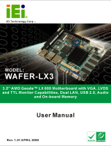
1.1 IMBA-8654 Overview
The IMBA-8654 motherboard is an LGA775 Intel® Pentium® 4/Intel® Pentium® D/Intel®
Celeron® D CPU platform with an Intel® 865G Express Chipset and Intel® I/O Controller
Hub 5 (ICH5) Southbridge. The IMBA-8654 has a maximum front side bus (FSB)
frequency of 800MHz, supports up to 4GB of dual channel 333/400MHz DDR RAM and
comes with VGA, PS/2 keyboard/mouse, COM port, parallel port, serial port and audio
interfaces as well as a Realtek/Intel® (GbE). The IMBA-8654 supports up to two serial
ATA (SATA 3Gb/s) hard disk drives and up to eight USB 2.0 devices.
1.1.1 IMBA-8654 Features
Some of the IMBA-8654 features are listed below.
RoHS compliant
Support for the following CPUs:
o LGA775 Intel® Pentium® 4
o LGA775 Intel® Pentium® D
o LGA775 Intel® Celeron® D
Integrated Intel® Extreme 2 graphics engine
Maximum FSB of 800MHz
Four 184-pin dual channel 333/400MHz DDR SDRAM DIMMs support up to
4GB of memory
High performance Realtek or Intel® Gigabit Ethernet chipset
Two SATA 3Gb/s drives supported
Four Ultra ATA 100, Ultra ATA 66 or Ultra ATA 33 IDE HDDs supported
Eight USB 2.0 devices supported
ATX power only
Realtek ALC655 chipset with AC ’97 CODEC
Expansion:
o 1 x AGP 8X slot
o 6 x PCI expansion slots
1.2 IMBA-8654 Overview
/