Panasonic TYKPLASMA600 Operating instructions
- Type
- Operating instructions

1
Made For
Panasonic
Plasma Wall-Hanging Bracket
TYWKPLASMA600
Assembly Instructions
(For list of applicable models see page3)
Contents
Foreword / Parts List …….…………………………………………............................ 2
Installation Instructions ….……………………………………………....................... 3
1. Fixing the wall hanging bracket to the wall ................................................. 4
2. Fixing the spacers to the display unit ……………………………………………………… 5
3. Attaching the display unit to the wall hanging bracket ……………….…………….. 6
Removing the display unit …………………………………………………………….…. 7
Support information:
Panasonic Customer Care Centre
For UK Customers call: 08705 357357
For Republic of Ireland Customers call: 01289 8333
Monday–Thursday 9.00am–5.30pm Friday 9.30am-5.30pm
(Excluding public holidays)
Email: [email protected]
www.panasonic.co.uk

2
Foreword
Warning!
Please seek professional advice and if in any doubt, have the installation carried out by a qualified tradesman.
Incorrect installation my result in damage to the Plasma display or personal injury.
The installation of the Plasma display unit onto the wall bracket must be carried out by a minimum of two people
to avoid the risk of damage to the display and possible personal injury.
Attention!
The installation of this wall bracket will require the following:
• A power drill
• A suitable screwdriver or spanner for your wall fixing
• A tape measure
• A spirit level
• Sufficient wall fixings for your application
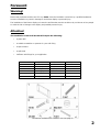
Item Description Part No. Quantity
1 Wall Bracket Z 0945 1
2 Velcro Strips C 0097 2
3 Assembly Screws F 0183 4
4 Mounting Spacer MAZ 0075 4
5 Allen Key AK 0001 1
6 Safety Screws F 0211 2
*Accessories available from customer care (see page 1)

3
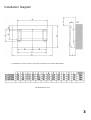
Installation Diagram
*A CLEARANCE OF AT LEAST 100mm AT THE TOP OF THE DISPLAY UNIT SHOULD BE PROVIDED
All dimensions in mm

4
Installation Instructions
1. Fixing the wall-hanging bracket to the
wall
A Select a suitable installation location
The wall hanging bracket weighs approximately 6kg and the display units
weigh between 28kg and 53kg depending on the model.
Please refer to the installation diagrams specific to your model, check the
strength of the wall at six locations and add reinforcements if any of
these locations are not strong enough.
B Measure and Mark
1. Select an installation site with an area suitable for your plasma,
ensuring that there is room for a 100mm clearance from the top of the
panel.
2. Establish where you wish the top centre of the Plasma to be. Measure
and mark B mm (please refer to specific ‘installation diagram’ – value B)
down from this point. This is now the top centre fixing point.
3. Drill and fasten an M6 screw / bolt into this top centre hole. Hang the
wall bracket on this fixing, using the top centre keyhole – gently tighten.
4. Use a spirit level to achieve the correct horizontal alignment of the
wall hanging bracket. Mark the remaining holes at the positions shown
below.
5. Remove the wall bracket and drill the marked 5 holes.
Units:mm
WALL INSTALLATION HOLES (6 locations)
Note:
The wall hanging
bracket has
installation holes
provided at 10
locations. If the wall
material is not
sufficiently sound to
support the unit using
6 holes suggested
then use as many
more as considered
necessary.

5
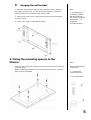
C Hanging the wall bracket
1. Hang the wall bracket on the top centre mounting screw, using the
top centre mounting hole. Re-check horizontal alignment, and when
satisfied fasten the remaining 5 fixing screws / bolts.
2. Tighten all 6 fixing screws / bolts and ensure that the wall mounting
bracket is secure
3. Fit the Velcro strips at the positions shown.
2. Fixing the mounting spacers to the
Plasma
Spread a clean cloth over a stable surface and carefully place the Plasma
on it face down.
With the ‘Allen Key’ install the four mounting spacers (item 4), using the
bolts (item 3) and tighten.
Note:
It is suggested that
commonly available
M6 wall fixing bolts
are used to secure the
wall bracket. If in
doubt seek
professional advice
Note:
Plasma Unit Mounting
components
3 – Countersunk
socket head screw
4 – Mounting Spacer

6
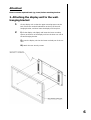
Attention!
Please connect required leads (eg. Scart) before attaching bracket.
3. Attaching the display unit to the wall-
hanging bracket
1 Lift the display unit so that the upper mounting spacers at the
back fit into the notched indentations at the top of the wall-
hanging bracket, and then lower the display unit into place.
2 i) Lift the display unit slightly and insert the lower mounting
spacers at the back of the display unit into the lower cut-outs in
the wall-hanging bracket.
ii) Lower the display unit into the lower notched part of the cut
outs.
iii) Attach the two security screws

7
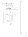
Removing the display unit
1) Remove the security screws
2) Lift the display slightly
3) At the same time, pull the bottom half away to detach the
lower mounting spacers
4) Lift the display away from the wall-hanging bracket
-
 1
1
-
 2
2
-
 3
3
-
 4
4
-
 5
5
-
 6
6
-
 7
7


Panasonic TYKPLASMA600 Operating instructions
- Type
- Operating instructions
Ask a question and I''ll find the answer in the document
Finding information in a document is now easier with AI
Related papers
-
Panasonic TY-SP42PWD3W User manual
-
-
-
-
-
-
-
-
-
Other documents
-
Comrac COMPA27 Datasheet
-
JVC TS-C50P2G User manual
-
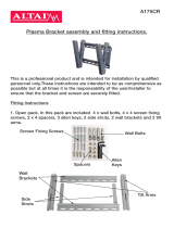 Altai A175CR Assembly And Fitting Instructions
-
Mounting Dream MD2351 User manual
-
Philex SLx 28050R User manual
-
Premier Mounts TV Mount PWM-F110 User manual
-
Pioneer 502MX User manual
-
 superior fires Radium Installation And User Instructions Manual
-
Focal Point P23+L23 User manual
-

