Page is loading ...

TG-T14-4,TG-T14-5,TG-T14-6,TG-T14-7,TG-T14-8,TG-T14-9,
TG-T15-4,TG-T15-5,TG-T15-6,TG-T15-7,TG-T15-8,TG-T15-9
TG-R4-26(TG-RX-MNLCAN),TG-R4-28(TG-RX-MNRCAN),TG-R4-30(TG-RX-MNPCAN),TG-R4-41(TG-RX-
MNLJ1939),TG-R4-43(TG-RX-MNRJ1939),TG-R4-45(TG-RX-MNPJ1939,TG-R4-36(TG-RX-MNLANA),
TG-R4-38(TG-RX-MNRANA),TG-R4-40(TG-RX-MNPANA)
LANGUAGE:English(original)
IM-TG2-RX009-CERT
Installation instructions

CONTENTS
Chapter 1: CUSTOMER INFORMATION 3
Chapter 2: SAFETY INFORMATION 5
Chapter 3: PRODUCT PAGES 7
TG-RX-MNLANA, TG-RX-MNRANA, TG-RX-MNPANA base board receiver with an expan-
sion board 8
TG-RX-MNLCAN, TG-RX-MNRCAN, TG-RX-MNPCAN, TG-RX-MNLJ1939, TG-RX-
MNRJ1939, TG-RX-MNPJ1939 base board receiver with CAN expansion board 17
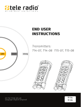
TG-T14-4, TG-T14-5, TG-T14-6, TG-T14-7, TG-T14-8, TG-T14-9, TG-T15-4, TG-T15-5,
TG-T15-6, TG-T15-7, TG-T15-8, TG-T15-9 transmitter 25
Chapter 4: INSTALLERS GUIDE 30
Navigate in menu mode 30
Enable PINcodes 30
Create PIN codes 31
Erase PIN codes 32
Show registered PIN codes 32
Start the transmitter in operating mode 33
Start the transmitter in operating mode with PIN codes 34
Turn the transmitter off 34
Login/logout 35
Register 36
Erase 37
Replace 38
Automatic shutdown 39
Frequencies & channels 40
Relay functionality 43
Digital inputs 44
Chapter 5: OPERATING MODES 45
Chapter 6: LOAD SELECT MODES 46
Chapter 7: BATTERY GUIDE 51
Chapter 8: CERTIFICATIONS CHAPTER 55
FCC/ IC 55
EC/EEA declaration of conformity 61
-2-

Chapter 1: CUSTOMER INFORMATION
CHAPTER 1: CUSTOMER INFORMATION
THANKYOUFORPURCHASINGATELERADIOABPRODUCT
READALLINSTRUCTIONS ANDWARNINGS CAREFULLY BEFOREMOUNTING, INSTALLING
ANDCONFIGURATING THEPRODUCTS.
These instructions are published by Tele Radio AB without any guarantee. The instructions may be
removed or revised by Tele Radio AB at any time and without further notice. Corrections and additions
will be added to the latest version of the instruction.
IMPORTANT! These instructions are directed to installers. There are separate instructions directed
towards end users. The instructions that contain information on the installation and configuration of the
radio remote control unit on the machine are not intended to be passed on to the end user. Only such
information may be passed on to the end user that is needed to operate the machine correctly by radio
remote control.
Tele Radio AB products are covered by a guarantee/ warranty against material, construction or
manufacturing faults. During the guarantee/ warranty period, Tele Radio AB may replace the product or
faulty parts with new. Work under guarantee/ warranty must be carried out by Tele Radio AB or by an
authorized service center specified by Tele Radio AB. Contact your Tele Radio AB representative if you
need support or service.
©Tele Radio AB
Datavägen 21
SE-436 36 ASKIM
SWEDEN
Tel: +46-31-748 54 60
Fax: +46-31-68 54 64
www.tele-radio.com
-3-

WARNINGS&RESTRICTIONS
WARNING! Tele Radio remote controls are often built into wider applications. We recommend that
the system is provided with a wired emergency stop where necessary.
NOTE! We recommend that the functionality of the STOP button is being tested at a regular basis: At a
minimum, when used for 200 hours. To test the STOP button: press, twist and pull it out.
INSTALLING, CONNECTING AND MOUNTING
nAllow only licensed or qualified personnel to install the product.
nSwitch the power supply off to the receiver before connecting the equipment.
nCheck that you have connected the power supply to the correct connection terminal.
nTo utilize the safety of the system, use the stop relays in the safety circuitry of the object that you
want to control.
nUse undamaged cables. No cables should hang loose.
nAvoid installing in areas affected by strong vibrations.
nPlace the receiver well away from wind, damp and water.
nCable glands and vent plugs must face down to prevent water from seeping in.
THE USER
nMake sure that the user is following the instructions.
nMake sure that the user has reached the certified age of your country to operate the equipment.
nMake sure that the user is not under the influence of drugs, alcohol and medicines.
nAllow only qualified personnel to have access to the transmitter and operate the equipment.
nMake sure that the user does not leave the transmitter unsupervised.
nMake sure that the user always turns the transmitter off when not in use.
nMake sure that the user keeps a good overview of the work area.
MAINTENANCE
nUse the stop button to start and turn off the transmitter as often as possible.
nWhen error messages are shown, it is very important to find out what caused them.
nIf the stop button is mechanically damaged, contact your representative for service immediately.
nAlways contact your representative for service and maintenance work on the product.
nWrite down the serial numbers/ ID codes of the receivers and transmitters used. This inform-
ation should be recorded on the “Settings document” for your product (download from our web-
site).
nAvoid registering transmitters to receivers where it is not being used.
nKeep the safety instruction for future reference. Always download the configurations instruction
from our web site for the latest version available.
-4-

Chapter 2: SAFETY INFORMATION
CHAPTER 2: SAFETY INFORMATION
APPLICATIONAREAFORTHETIGERSYSTEM
The Tele Radio AB Tiger remote control systems are aimed for remote controlling of lifting or mobile
equipment where a high safety level is required.
AUTHORIZATIONBYPINCODE
To prevent from unauthorized users being able to start the transmitter and control the receiver, you can
enable PIN codes for start-up protection. 1-10 PIN codes can be stored in the transmitters.
STOPFUNCTION
The transmitters have a stop button that controls the 2 stop relays in the receiver. 2 safety
microcontrollers are supervising and controlling the stop relays. A valid signal must be provided from
both microcontrollers to activate the stop relays.
-5-

SAFETYINFORMATION(INENGLISH)
System requirements
The product holds a safety-related stop function that complies with the requirements for SIL3 according
to IEC61508:
The stop function deactivates all relays on the receiver when the stop button on the transmitter is
pressed. The stop function is available on all Tiger systems. The maximum delay of the stop function is
500 ms. The stop function complies with the requirements for SIL3 according to IEC61508 only when it
is a part of a complete end user system that complies with the requirements for SIL3 according to
IEC61508.
Connecting and controlling the safety function
The stop function controls the stop relays from the stop button. In order to comply with the
requirements for SIL3 according to IEC61508, the safety-related function shall use its corresponding
two relay output in an active redundant configuration in a safety-related application.
Measures for probability of hardware failures
Transmitter stop function
Probability of dangerous failure per hour PFHd= 8.5 FITs (=λdu)
Fraction of total failure rate with dangerous and
detected consequence λdd= 357 FITs
Diagnostic coverage DC= 98.3%
Safe failure fraction SFF= 99.1 %
Common cause failure 0 FIT
Level of hardware fault tolerance HFT = 1
Proof test interval 10 years
Diagnostic test interval Continuous
Receiver stop function
Probability of dangerous failure per hour PFHd = 30.1 FITs (=λdu)
Fraction of total failure rate with dangerous and
detected consequence λdd = 685.0 FITs
Diagnostic coverage DC = 96.9 %
Safe failure fraction SFF = 98.7 %
Common cause failure 8.0 FIT
Level of hardware fault tolerance HFT = 1
Proof test interval 10 years
Diagnostic test interval Continuous
Radio communication between transmitter and
receiver
Probability of dangerous failure per hour PFHd = 3.0 FITs
Stop functionfor a completesystem*
Probability of dangerous failure per hour PFHd = 41.6 FITs(=λdu)
* Acomplete system = transmitter + radio communication + receiver
-6-

Chapter 3: PRODUCT PAGES
CHAPTER 3: PRODUCT PAGES
ANTENNA
NOTE! For optimum performance: Place well away from metal objects, such as metal girders, high-
voltage cables and other antennas.
NOTE! For optimum performance, place the antennas as far away from each other as possible. The
recommended distance is more than 1 meter. We recommend that you test the equipment before
mounting the receivers permanently.
Antenna with a cable: The cable makes it possible for the antenna to be positioned freely and high above
the ground.
Antenna without a cable:If the receiver is mounted on a wall, the antenna should be angled out from the
wall.
-7-

TG-RX-MNLANA,TG-RX-MNRANA,TG-RX-MNPANABASE
BOARDRECEIVERWITHANEXPANSIONBOARD
WARNING! The receiver must NOT be opened by any other than a qualified installer. Make sure to
turn the electricity off before opening the receiver.
WARNING! Tele Radio remote controls are often built into wider applications. We recommend that
the system is provided with a wired emergency stop where necessary.
Base board:
1. LED representing stop relays 1+2 (red) 8. Antenna connector
2. Stop relays 1+2 9. Function LEDs 1-4 (1= red, 2= yellow, 3=
green, 4= orange)
3. Obligatory fuse 2A (slow) 10. Function button (Cancel)
4. Terminal block for input power 11. Terminal block for mixed I/O
5. Function relays 1-7 12. Select button (OK)
6. Relay LEDs 1-7 (red) 13. Programming connector
7. Function LEDs 5-7 (5= red, 6= yellow, 7=
green) 14. Power LED (yellow)
-8-

Expansion board:
15. Terminal block for analogue outputs 23. Function relays 22-25
16. Indication LED for communication with the
base board (green) 24. Terminal block for digital outputs
17. Programming connector 25. Terminal block for external analogue reference
and isolated analogue supply
18. Function button (Cancel) 26.Digital outputs LEDs
19. Select button (OK) 27. Indication LED for internal DC/DC converter
(yellow)
20. Terminal block for digital inputs 28. Indication LED for communication with the
base board (green)
21. Function relay LEDs (red) 29. Terminal block for analogue inputs
22. LEDs representing stop relays 1-2 and
function relays 1-7 on the base board
-9-

TERMINALBLOCKFORINPUTPOWER
1. 48-230 V AC
2. 48-230 V AC
3. (not used)
4. ~12-24 V AC/DC
5. negative terminal DC voltage*
6. ~+12-24 V AC/DC
* use when digital inputs are connected to receiver
TERMINALBLOCKFORMIXEDI/O
32. +12V DC 38. Digital input 2
33. +5V DC 39. GND
34. GND 40. +3.3V DC
35. GND 41. RS485A-
36. Digital input 1 42. RS485B+
37. Transistor output 43. GND
-10 -

FUNCTIONLEDSINDICATIONINOPERATINGMODE
FunctionLED Off On Indicates...
1 (red) X No transmitter is registered
X One or more transmitters are registered
2 (yellow) X No transmitter is logged in
X One transmitter is logged in
3 (green) X Receiving correct RS485 data
4 (orange) X Settings in the safety CPUs conform to SIL3
X Settings in the safety CPUs do NOT conform to SIL3
5 (red)
X FLASHES: The receiver is frequency scanning
X Automatic frequency control processing
X Automatic frequency control finetuned
6 (yellow) X Receiving correct sync word
7 (green) X Receiving correct radio packet
-11 -

TERMINALBLOCKFOREXTERNALANALOGUEREFERENCE
ANDISOLATEDANALOGUESUPPLY
How to connect to the terminal block depends on the configurations made to the receiver. Please,
contact your Tele Radio representative for further assistance.
50. Unconnected
51. Unconnected
52. Unconnected
0 to +10V analogue output, internal DC/DC converter on:
50. Negative supply
51. Unconnected
52. Positive supply
0 to +10V analogue output, internal DC/DC converter off:
50. Unconnected
51. External reference*
52. Unconnected
-10 to +10V analogue output, internal DC/DC converter on***:
50. Negative supply
51. External reference*
52. Positive supply
-10 to +10V analogue output, internal DC/DC converter off**:
-12 -

50. Negative supply
51. Unconnected
52. Positive supply
25-75% or 10-90% output****:
* Analogue output reference will follow this voltage. If unconnected, the analogue output reference will
be in the middle of the external supply voltage.
** External supply voltage of 22-35V DC is required to achieve full -10 to +10V output.
*** External supply voltage shall not be connected. Guaranteed output range is -5 to +5V.
**** Internal DC/DC converter is always off. The analogue output voltage is 25-75% or 10-90% of the
supply voltage, depending on the configurations of the receiver.
TERMINALBLOCKFORDIGITALOUTPUTS
There are 12 digital outputs on the expansion board. The digital outputs can be remapped as with the
relays. Maximum input is 50V, 30 mA.
53. Digital output 10 65. Digital output 16
54. Digital output 10 reference 66. Digital output 16 reference
55. Digital output 11 67. Digital output 17
56. Digital output 11 reference 68. Digital output 17 reference
57. Digital output 12 69. Digital output 18
58. Digital output 12 reference 70. Digital output 18 reference
59. Digital output 13 71. Digital output 19
60. Digital output 13 reference 72. Digital output 19 reference
61. Digital output 14 73. Digital output 20
62. Digital output 14 reference 74. Digital output 20 reference
63. Digital output 15 75. Digital output 21
64. Digital output 15 reference 76. Digital output 21 reference
-13 -

TERMINALBLOCKFORDIGITALINPUTSANDGROUND
CONNECTIONS
77. Digital input 3 80. GND
78. Digital input 4 81. GND
79. Digital input 5 82. GND
TERMINALBLOCKFORANALOGUEINPUTS
83. Analogue input 1
84. Analogue input 2
85. Analogue GND
TERMINALBLOCKFORANALOGUEOUTPUTS
86. Analogue GND 93. Analogue output 1
87. Analogue GND 94. Analogue output 2
88. Analogue GND 95. Analogue output 3
89. Analogue GND 96. Analogue output 4
90. Analogue GND 97. Analogue output 5
91. Analogue GND 98. Analogue output 6
92. Analogue GND 99. Analogue output 7
-14 -

BASEBOARDRELAYLEDS
These LEDs light when the corresponding stop and function relays on the base board are activated. See
list for corresponding base board relay.
LED 1 = function relay 1
LED 2 = function relay 2
LED 3 = function relay 3
LED 4 = function relay 4
LED 5 = function relay 5
LED 6 = function relay 6
LED 7 = function relay 7
LED 8 = (not used)
LED 9 = stop relays 1 + 2
CURRENTCONSUMPTION
Input power Min.* Max.**
12V AC 0.2A 0.5A
24V AC 0.06A 0.2A
48V AC 0.04A 0.2A
115V AC 0.02A 0.06A
230V AC 0.01A 0.04A
12V DC 0.1A 0.5A
24V DC 0.06A 0.2A
* Minimum current consumption= Receiver powered, no radio session established, nothing else
activated on the receiver
** Maximum current consumption= All relays activated on the receiver
-15 -

TECHNICALDATA
Number of stop relays 2 (potential free*, 16A, 250VAC)
Number of function relays 7 (potential free*, 10A, 250VAC)
Digital inputs 2
Input power 48-230V AC, 12-24V AC/DC
Transistor output 1
Duplex communication Possible
Max. number of registered
transmitters 15 (only one transmitter at a time)
IP class 66
Size 176 x 126 x 75 mm./ 6.9 x 5 x 2.9 in.
Weight 800 g./ 1.8 lbs.
Sensitivity Better than -110 dBm
Operating temperature -20- +55°C/ -4-+130°F
Operating frequency
TG-RX-MNLANA: 433.075-434.775 MHz
TG-RX-MNRANA: 903.0125-926.9875 MHz
TG-RX-MNPANA: 2405-2480 MHz
Number of channels/frequency banks
TG-RX-MNLANA: 69 channels
TG-RX-MNRANA: 15 banks
TG-RX-MNPANA: 16 channels
Channel separation
TG-RX-MNLANA: 25 kHz
TG-RX-MNRANA: 25 kHz
TG-RX-MNPANA: 5 MHz
Antenna
TG-RX-MNLANA: 1 external BNC antenna
TG-RX-MNRANA: 1 external RPSMA antenna
TG-RX-MNPANA: 1 external RPSMA antenna
* potential free means that you have to supply voltage to get voltage out of a relay (e.g. via the included
connection comb)
-16 -

TG-RX-MNLCAN,TG-RX-MNRCAN,TG-RX-MNPCAN,TG-RX-
MNLJ1939,TG-RX-MNRJ1939,TG-RX-MNPJ1939BASEBOARD
RECEIVERWITHCANEXPANSIONBOARD
WARNING! The receiver must NOT be opened by any other than a qualified installer. Make sure to
turn the electricity off before opening the receiver.
WARNING! Tele Radio remote controls are often built into wider applications. We recommend that
the system is provided with a wired emergency stop where necessary.
Base board:
1. LED representing stop relays 1+2 (red) 8. Antenna connector
2. Stop relays 1+2 9. Function LEDs 1-4 (1= red, 2= yellow, 3=
green, 4= orange)
3. Obligatory fuse 2A (slow) 10. Function button (Cancel)
4. Terminal block for input power 11. Terminal block for mixed I/O
5. Function relays 1-7 12. Select button (OK)
6. Relay LEDs 1-7 (red) 13. Programming connector
7. Function LEDs 5-7 (5= red, 6= yellow, 7=
green) 14. Power LED (yellow)
-17 -


TERMINALBLOCKFORINPUTPOWER
1. 48-230 V AC
2. 48-230 V AC
3. (not used)
4. ~12-24 V AC/DC
5. negative terminal DC voltage*
6. ~+12-24 V AC/DC
* use when digital inputs are connected to receiver
TERMINALBLOCKFORMIXEDI/O
32. +12V DC 38. Digital input 2
33. +5V DC 39. GND
34. GND 40. +3.3V DC
35. GND 41. RS485A-
36. Digital input 1 42. RS485B+
37. Transistor output 43. GND
-19 -

FUNCTIONLEDSINDICATIONINOPERATINGMODE
FunctionLED Off On Indicates...
1 (red) X No transmitter is registered
X One or more transmitters are registered
2 (yellow) X No transmitter is logged in
X One transmitter is logged in
3 (green) X Receiving correct RS485 data
4 (orange) X Settings in the safety CPUs conform to SIL3
X Settings in the safety CPUs do NOT conform to SIL3
5 (red)
X FLASHES: The receiver is frequency scanning
X Automatic frequency control processing
X Automatic frequency control finetuned
6 (yellow) X Receiving correct sync word
7 (green) X Receiving correct radio packet
TERMINALBLOCKFORINTERNALPOWERSUPPLY
58. GND
57. +5V DC
56. GND
TERMINALBLOCKFORCANSIGNALS
50. Supply voltage 5-24VDC
51. GND
52. CAN Low
53. CAN Low
54. CAN High
55. CAN High
-20 -
/