Page is loading ...

Panther
Installation instructions
IM-PN-TX105-A04-EN
Language: English (original)
PN-T21-3
PN-T21-4
PN-T21-6
PN-T21-8
PN-T21-10
Transmitters

CONTENTS
CHAPTER 1: CUSTOMER INFORMATION 3
Thank you for purchasing a TeleRadioAB product 3
About this document 4
Warnings & restrictions 4
CHAPTER 2: PRODUCT DESCRIPTION 6
Transmitter front 6
Transmitter back 7
Technical data 7
Frequency band 8
CHAPTER 3: OPERATION 9
Register the transmitter in the receiver 9
Start the transmitter 9
Switch the transmitter off 9
CHAPTER 4: CONFIGURATION SETTINGS 10
Radio mode 10
Automatic shutdown 10
Erase all transmitters from the receiver 10
Load select mode 10
CHAPTER 5: BATTERY GUIDE 11
Battery precautions 11
Battery information 12
Change batteries 12
CHAPTER 6: GUARANTEE, SERVICE, REPAIRS AND MAINTENANCE 13
CHAPTER 7: REGULATORY INFORMATION 14
CE marking 14
WEEE directive 14
FCCstatement 14
IC Statement 15
ANNEX A: FREQUENT TERMS 16

CHAPTER 1: CUSTOMER INFORMATION
THANK YOU FOR PURCHASING A TELE RADIO AB PRODUCT
Read all instructions and warnings carefully before mounting, installing and
configuring the products.
These instructions have been published by Tele Radio AB and are not subject to any guarantee. The
instructions may be withdrawn or revised by Tele Radio AB at any time and without further notice.
Corrections and additions will be added to the latest version of the instructions. Always download the
installation instructions from our website, www.tele-radio.com, for the latest available version. Keep the
safety instructions for future reference.
IMPORTANT! These instructions are intended for installers. The instructions
containing information about the installation and configuration of the radio remote
control unit on the machine are not intended to be passed on to the end user. Only
information that is needed to operate the machine correctly by radio remote control may be passed on
to the end user.
Tele Radio AB remote controls are often built into wider applications. Always refer to the applicable
local regulations for installation and safety requirements relating to cranes, hoists or other material
handling and/or lifting equipments using Tele Radio AB products, e.g.:
napplicable local and industrial standards and requirements,
napplicable occupational health and safety regulations,
napplicable safety rules and procedures for the factory where the equipment is being used,
nuser and safety manuals or instructions of the manufacturer of the equipment where Tele Radio
AB remote control systems are installed.
Tele Radio AB instructions do not include or address the specific instructions and safety warnings of the
end product manufacturer.
For battery precautions, see "Battery precautions" on page11.
Tele Radio AB products are covered by a guarantee/warranty against material, construction or
manufacturing faults, see "GUARANTEE, SERVICE, REPAIRS AND MAINTENANCE" on page13
©Tele Radio AB
Datavägen 21
SE-436 32 ASKIM
SWEDEN
Tel: +46-31-748 54 60
www.tele-radio.com
- 3 -

ABOUT THIS DOCUMENT
Every care has been taken in the preparation of this manual. Please inform Tele Radio AB of any
inaccuracies or omissions.
These installation instructions cover general safety issues, main technical specifications, standard
installation, configuration and operating instructions, general troubleshooting and battery information.
Images shown in this document are for illustrative purposes only.
Term and symbol definitions
The capitalized terms and symbol used herein shall have the following meaning:
nWARNING! indicates a hazardous situation which, if not avoided, could result in death or
serious injury.
nCAUTION! indicates a hazardous situation which, if not avoided, will result in minor or
moderate injury.
nIMPORTANT! is used for information that requires special consideration.
nNOTE! is used to address practices not related to physical injury.
This symbol is used to call attention to safety messages that would be assigned the signal words
"WARNING"or "CAUTION".
WARNINGS & RESTRICTIONS
Carefully read through the following safety instructions before proceeding
with the installation, configuration, operation or maintenance of the product.
Failure to follow these warnings could result in serious injury and property
damage.
Installing, connecting and mounting
nThis radio system must not be used in areas where there is a risk of explosion.
nTele Radio AB remote controls are often built into wider applications. Those systems
should be equipped with:
na wired emergency stop where necessary.
na brake.
nan audible or visual warning signal.
nAlways switch off all electrical power from the equipment before installation procedure.
nOnly licensed or qualified personnel should be permitted to install the product.
nTo utilize the safety of the system, use the stop relays in the safety circuitry of the object
that you want to control.
nWhen the equipment controlled by the receiver's standard relays is connected via the
stop relays, make sure that the maximum current through the stop relays is still within
the specifications. Contact your representative for assistance.
nAvoid registering transmitters in receivers where they are not being used.
- 4 -

Operation
nOnly qualified personnel should be permitted to access the transmitter and operate the
equipment.
nMake sure that the user satisfies the age requirements in your country for operating the
equipment.
nMake sure that the user is not under the influence of drugs, alcohol and medications.
nMake sure that the user knows and follows operating and maintenance instructions as
well as all applicable safety procedures and requirements.
nThe user should:
nalways test the transmitter stop button before operating it. Press the stop button
then twist and pull it out. This test should be done on each shift, without a load.
nnever use a transmitter if the stop button is mechanically damaged. Contact your
supervisor/representative for service immediately.
nnever let the transmitter unattended.
nalways switch the transmitter off when not in use. Store in a safe place.
nkeep a clear view of the work area at all times.
Maintenance
nKeep the safety instructions for future reference. Always download the configuration instruc-
tions from our website for the latest available version.
nAlways contact your representative for service and maintenance work on the product.
nWrite down the serial numbers/ ID codes of the receivers and transmitters used. This inform-
ation should be recorded in the “Settings document” for your product (can be downloaded from
www.tele-radio.com).
nIf error messages are shown, it is very important to find out what caused them. Contact your rep-
resentative for help.
nThe functionality of the stop button should be tested at least after every 200 hours’ use. Test the
stop button by pressing it and pulling it out.
nIf the stop button is mechanically damaged, do not use the transmitter. Contact your rep-
resentative for service immediately.
nBefore maintenance intervention on any remote controlled equipments:
nalways remove all electrical power from the equipment.
nalways follow lockout procedures.
- 5 -

CHAPTER 2: PRODUCT DESCRIPTION
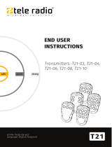
TRANSMITTER FRONT
NOTE! Performing a “factory reset” of the unit will return the settings to the factory defaults and all
button remapping will be lost.
PN-T21-10 PN-T21-8
3
24
15
8
7
6
9
14 15
11
12
10
13
3
24
15
8
7
6
911
12
10
13
PN-T21-6 PN-T21-4
3
24
15
8
7
6
911
10
3
24
15
7
9
6
8 **
*
PN-T21-3
3
24
15
8
7
6
1. LED 1 (red)
2. LED 2 (red)
3. Top LED (red, green)
4. LED 3 (red)
5. LED 4 (red)
6. Button 1
7. Button 2
8. Button 3
9. Button 4
10. Button 5
11. Button 6
12. Button 7
13. Button 8
14. Button 9
15. Button 10
*On PN-T21-4, the default buttons 3, 4 and 6 have been remapped to work as buttons 2, 3 and 4.
Contact your representative for more details.
- 6 -

TRANSMITTER BACK
Model: 000000000
FCC ID: ABCD0000E
IC: 0000A-B0000D
www.tele-radio.com
2
1
3
1. I/O switch
2. Clip
3. Product label
I/O switch
The I/O switch on the back of the transmitter interrupts the power supply from the battery. When in the
O/off position, the transmitter cannot be started unless the charger plug is connected.
IMPORTANT! When the transmitter is to be transported by air, the I/O switch must be
in the O/off position.
NOTE! The I/Oswitch should not be used as an on/off button for the transmitter. To start and stop the
transmitter, use the stop button.
TECHNICAL DATA
PN-T21-10 PN-T21-8 PN-T21-6 PN-T21-4 PN-T21-3
Number of buttons 10 x 1-step
button
8 x 1-step
button
6 x 1-step
button
4 x 1-step
button
3 x 1-step
button
Battery 3 x 1.5V AAA / LR03 Alkaline
I/O switch Yes
Radio communication Simplex
Dimensions 66 x 114 x 37.5 mm / 2.6 x 4.5 x 1.5 in
Weight 135 g / 0.29 lbs
Frequency band 2405–2480 MHz
Number of channels 16 (channel 11–26)
Radio frequency output
power
<10mW
IP code 67
Operating temperature -20…+55 °C / -4…+130 °F
- 7 -

FREQUENCY BAND
Channel Frequency
11 2405 MHz
12 2410 MHz
13 2415 MHz
14 2420 MHz
15 2425 MHz
16 2430 MHz
17 2435 MHz
18 2440 MHz
19 2445 MHz
20 2450 MHz
21 2455 MHz
22 2460 MHz
23 2465 MHz
24 2470 MHz
25 2475 MHz
26 2480 MHz
- 8 -

CHAPTER 3: OPERATION
REGISTER THE TRANSMITTER IN THE RECEIVER
Do not perform this action when the receiver is in a session with another
transmitter. The radio communication may be interrupted or broken.
NOTE! Only keep the transmitters that you intend to use registered in the receivers.
NOTE! To establish a radio link between the transmitter and the receiver, both units must be set to the
same radio mode.
1. Press the receiver Function button.
The function LED lights (red).
2. Press the receiver Select button.
The relay LEDs light (red).
3. Press buttons 1 and 2. Keep pressed.
The relay LEDs light (red). The relay LEDs flash (red) 2 times.
4. Release buttons 1 and 2.
The relay LEDs flash (red) 1 time.
The transmitter is registered.
If no transmitter is found within approximately 10 seconds, the receiver exits to normal operation.
START THE TRANSMITTER
1. Start the transmitter by pressing any button on the transmitter.
The top LED lights (green when the battery capacity is good, red when the battery capacity is
poor).
SWITCH THE TRANSMITTER OFF
1. The transmitter switches off when no transmitter button is pressed.
- 9 -

CHAPTER 4: CONFIGURATION SETTINGS
RADIO MODE
NOTE! You cannot change the radio mode from the transmitter. Contact your representative for
assistance.
NOTE! To establish a radio link between the transmitter and the receiver, both units must be set to the
same radio mode.
This transmitter is set to discontinuous radio mode by default. The transmitter starts transmitting as
soon as the batteries are inserted and any transmitter button is pressed. Radio transmission ends when
all transmitter buttons are released.
AUTOMATIC SHUTDOWN
NOTE! Only for continuous radio mode.
NOTE! You cannot change the automatic shutdown time from the transmitter. Contact your
representative for assistance.
Automatic shutdown can save battery capacity by automatically switching the transmitter off following a
preset period of inactivity.
The transmitter automatic shutdown time is set to 3 minutes by default.
ERASE ALL TRANSMITTERS FROM THE RECEIVER
1. Press the receiver Function button.
The function LED lights (red).
2. Press the receiver Select button. Keep pressed (at least 4 seconds).
All relay LEDs light (red). All relay LEDs go out.
3. Release the receiver Select button.
All transmitters are erased from the receiver.
If the function LED flashes (red), one or more transmitters are still registered in the receiver.
LOAD SELECT MODE
NOTE! You cannot change the Load select mode from the transmitter. Contact your representative for
assistance.
Load select mode is deactivated by default (Load select mode 0).
- 10 -

CHAPTER 5: BATTERY GUIDE
BATTERY PRECAUTIONS
Carefully read through the following safety instructions and warnings before using,
charging or disposing of the batteries.
Batteries contain flammable substances such as lithium or other organic solvents, which may
result in overheating, rupture or combustion. Failure to read and follow the below instructions
may result in fire, personal injury and damage to property if charged or used improperly.
Handling and storage
nRisk of explosion if battery is replaced with a battery of an incorrect type.
nDo not short circuit, disassemble, deform or heat batteries.
nNever attempt to charge a visibly damaged or frozen battery.
nDo not use or charge the battery if it appears to be leaking, deformed or damaged in
any way.
nDo not solder directly onto batteries.
nDo not leave the battery in the charger once it is fully charged.
nStore in a cool location. Keep batteries away from direct sunlight, high temperature,
and high humidity.
nImmediately discontinue use of the battery if, while using, charging, or storing the bat-
tery, the battery emits an unusual smell, feels hot, changes color, changes shape, or
appears abnormal in any other way.
nKeep batteries out of reach of small children. Should a child swallow a battery, consult
a physician immediately.
Disposal
When discarding batteries, insulate the + and - terminals of batteries with insulating/ masking tape.
nDo not place multiple batteries in the same plastic bag.
nDo not incinerate or dispose of batteries in fire.
nDo not place used batteries in the household waste. Dispose of used batteries in accord-
ance with the applicable regulations and legal requirements.
nBatteries that have been disposed of incorrectly may short circuit, causing them to
become hot, burst or ignite.
- 11 -

BATTERY INFORMATION
Do not recharge the batteries. Attempts to recharge may cause rupture or
hazardous liquids to leak, which will corrode the equipment.
NOTE! Electronics and batteries must be physically separated before disposal. Make sure that
electronics or batteries are not disposed of in household waste.
NOTE! When approximately 10 % of battery capacity remains, the top LED lights red.
CHANGE BATTERIES
Battery type: 3 x 1.5V AAA / LR03 Alkaline
1. Remove the back of the transmitter by unscrewing the 5 screws.
2. Replace the 3 x 1.5V AAA batteries. Use alkaline batteries for
optimal performance.
3. Screw the back of the transmitter into place.
- 12 -

CHAPTER 6: GUARANTEE, SERVICE, REPAIRS AND
MAINTENANCE
Tele Radio AB products are covered by a guarantee/warranty against material, construction and
manufacturing faults. During the guarantee/warranty period, Tele Radio AB may replace the product or
faulty parts. Work under guarantee/warranty must be carried out by Tele Radio AB or by an authorized
service centre specified by Tele Radio AB.
The following are not covered by the guarantee/warranty:
nFaults resulting from normal wear and tear.
nParts of a consumable nature.
nProducts that have been subject to unauthorized modifications.
nFaults resulting from incorrect installation and use.
nDamp and water damage.
Maintenance:
nRepairs and maintenance must be carried out by qualified personnel.
nOnly use spare parts from Tele Radio AB.
nContact your representative for service or any other assistance.
nKeep the product in a clean, dry place.
nKeep contacts and antennas clean.
nWipe off dust using a slightly damp, clean cloth.
NOTE! Never use cleaning solutions or high-pressure washer.
- 13 -

CHAPTER 7: REGULATORY INFORMATION
Applies to: PN-T21-3, PN-T21-4, PN-T21-6, PN-T21-8, PN-T21-10
CE MARKING
Hereby, Tele Radio AB, declares that the radio equipment type(s) listed above is/ are in compliance with
Directive 2014/53/EU.
The latest version of the complete EU Declaration of Conformity is available on the Tele Radio AB
website, www.tele-radio.com.
WEEE DIRECTIVE
This symbol means that inoperative electrical and electronic products must not be mixed
with household waste.The European Union has implemented a collection and recycling
system for which producers are responsible. For proper treatment, recovery and recycling,
please take this product to a designated collection point.
Tele Radio AB strives to minimize the use of hazardous materials, promotes reuse and recycling, and
reduces emissions to air, soil and water. When a commercially viable alternative is available, Tele Radio
AB strives to restrict or eliminate substances and materials that pose an environmental, health or safety
risk.
FCC STATEMENT
This device complies with part 15 of the FCC Rules. Operation is subject to the following two
conditions:
(1) This device may not cause harmful interference, and
(2) this device must accept any interference received, including interference that may cause undesired
operation.
Changes or modifications not expressly approved by the party responsible for compliance could void
the user’s authority to operate the equipment.
This equipment has been tested and found to comply with the limits for a Class B digital device, pursuant
to part 15 of the FCC Rules. These limits are designed to provide reasonable protection against harmful
interference in a residential installation. This equipment generates uses and can radiate radio frequency
energy and, if not installed and used in accordance with the instructions, may cause harmful interference
to radio communications. However there is no guarantee that interference will not occur in a particular
installation. If this equipment does cause harmful interference to radio or television reception, which can
be determined by turning the equipment off and on, the user is encouraged to try to correct the
interference by one or more of the following measures:
nReorient or relocate the receiving antenna.
nIncrease the separation between the equipment and receiver.
nConnect the equipment into an outlet on a circuit different from that to which the receiver is con-
nected.
nConsult the dealer or an experienced radio/TV technician for help.
To satisfy FCC RF exposure requirements, a separation distance of 20 cm or more should be maintained
between the antenna of this device and persons during device operation.
To ensure compliance, operations at closer than this distance is not recommended.
- 14 -

IC STATEMENT
This product complies with Industry Canada's licence-exempt RSSs. Operation is subject to the
following two conditions:
(1) This device may not cause interference;and
(2) This device must accept any interference, including interference that may cause undesired operation
of device.
Le présent appareil est conforme aux CNR d’Industrie Canada applicables aux appareils radio exempts
de licence. L’exploitation est autorisée aux deux conditions suivantes :
1. l’appareil ne doit pas produire de brouillage;
2. l’appareil doit accepter tout brouillage radioélectrique subi, même si le brouillage est susceptible
d’en compromettre le fonctionnement.
To satisfy IC RF exposure requirements, a separation distance of 20 cm or more should be maintained
between the antenna of this device and persons during device operation. To ensure compliance,
operations at closer than this distance is not recommended.
Afin d'assurer la conformité aux exigences de la ICen matière d'exposition aux RF, une distance de
séparation d'au moins 20 cm doit être maintenue entre l'antenne de cet appareil et toute personne à
proximité pendant le fonctionnement de l'appareil. Pour assurer le respect de ces exigences, il n'est pas
recommandé d'utiliser l'appareil à une distance inférieure à celle-ci.
- 15 -

ANNEX A: FREQUENT TERMS
Configuration ID Numerical code stored in both the transmitter and receiver unit. The receiver unit
can only be controlled by a transmitter with the correct configuration ID.
Continuous radio
mode
When in continuous radio mode the transmitter unit transmits continuously when
it is switched on.
Custom ID
Numerical code stored in the transmitter unit, used to replace the unique ID code.
One or several transmitter units can be configured with the same custom ID and
the receiver will recognise them all as the same transmitter unit.
Discontinuous radio
mode
When in discontinuous radio mode the transmitter unit transmits whenever it is
switched on and a button is pressed. The transmission is interrupted when all but-
tons are released.
Function relay Standard relay, controlled by the buttons on the transmitter unit.
Interlocking Prevents a component from functioning when another component is functioning
or operating in a particular way.
Latching relay
functionality
The relay becomes active every time you press a button and remains active until
the button is pressed again.
Load select mode
One or more Load select modes are stored in the transmitter unit. Activating a spe-
cific Load select mode results in a group of preselected relays on the receiver unit,
which may be controlled from the transmitter unit.
Momentary relay
functionality
The relay will only be active while a button is pressed on the transmitter. When
the button is released, the relay will no longer be active.
On relay Relay that is active when the receiver unit is operating and a radio link is estab-
lished, regardless of whether any other relays are active.
Operating mode
One or more Operating modes are stored in the receiver unit. Each Operating
mode describes which relays on the receiver unit are controlled when specific but-
tons on the transmitter unit are pressed.
Replace ID Numerical code used to identify the transmitter during the Replace procedure.
Stop relay Safety related relay controlled by the stop button on the receiver. Intended to inter-
rupt the power supply to a safety application controlled by the receiver unit.
Work relay Relay that is active when any other specified relay(s) on the receiver unit is/are act-
ive.
Zero position check
Security function ensuring that potentially active buttons/joysticks upon start up
or lost/found radio links must be in the zero position before the system can be
used to avoid unplanned movements of the controlled object.
- 16 -

(This page has intentionally been left blank)
- 17 -

These installation instructions are subject to change without prior notice.
Download the latest installation instructions from www.tele-radio.com
/