Page is loading ...

Pag. 1 / 44 DMAN802000066-SY250 Idro 4/8 Buttons Manual
SY250 IDRO 4/8
BUTTONS MANUAL

Pag. 2 / 44 DMAN802000066-SY250 Idro 4/8 Buttons Manual
Summary
1 INTRODUCTION ...................................................................................................................... 4
2 INSTALLATION ........................................................................................................................ 4
2.1 CONNECTIONS ............................................................................................................................. 4
2.2 DIGITAL INPUTS ........................................................................................................................... 7
2.2.1 Safety High Voltage 1 .......................................................................................................... 7
2.2.2 Safety High Voltage 2 .......................................................................................................... 7
2.2.3 Encoder .............................................................................................................................. 7
2.2.4 Pellet Level Input ................................................................................................................ 7
2.3 ROOM PROBE OR THERMOSTAT ........................................................................................................ 7
2.3.1 Room Probe ........................................................................................................................ 7
2.3.2 Room Thermostat ............................................................................................................... 8
2.4 BUFFER PROBE OR FLOW SWITCH ..................................................................................................... 8
2.4.1 Buffer Probe ....................................................................................................................... 8
2.4.2 Flow Switch ........................................................................................................................ 8
2.5 ANALOGUE INPUTS ........................................................................................................................ 8
2.5.1 Thermocouple (Exhaust Probe) ............................................................................................ 8
2.5.2 Boiler Probe ........................................................................................................................ 8
2.5.3 Pressure Sensor .................................................................................................................. 8
2.5.4 Primary Air Flow Sensor ....................................................................................................... 9
3 CONTROL PANEL ................................................................................................................... 10
3.1 USER MENU 1............................................................................................................................ 11
3.2 USER MENU 2............................................................................................................................ 12
3.2.1 Heating Power Menu ......................................................................................................... 12
3.2.2 Thermostats Menu ............................................................................................................ 12
3.2.3 Chrono Menu .................................................................................................................... 13
3.2.4 Combustion Recipe Menu .................................................................................................. 14
3.2.5 Remote Keyboard Thermostat Enable Menu ........................................................................ 14
3.2.6 Time and Date Menu ......................................................................................................... 14
3.2.7 Summer - Winter Menu ..................................................................................................... 14
3.2.8 Remote Control Menu ........................................................................................................ 14
3.2.9 Learn Menu ...................................................................................................................... 14
3.3 SYSTEM MENU ........................................................................................................................... 15
3.3.1 Auger Menu (TP01) ........................................................................................................... 15
3.3.2 Combustion Fan Menu (TP02) ............................................................................................ 15
3.3.3 Heatingn Fan Menu (TP03) ................................................................................................ 16
3.3.4 Thermostats Menu (TP04) ................................................................................................. 16
3.3.5 Timers Menu (TP05) .......................................................................................................... 17
3.3.6 Default Settings Menu (TP06) ............................................................................................ 17
3.3.7 Pressure Sensor Threshold Menu (TP07) ............................................................................ 18
3.3.8 Enable Menu (TP08) .......................................................................................................... 18
3.3.9 Temperature Delta Menu (TP09) ........................................................................................ 19
3.3.10 Counters Menu (TP11) ................................................................................................... 19
3.3.11 Outputs Test Menu (TP12) ............................................................................................. 20
3.3.12 Extinguishing Thermostats Menu (TP13) ......................................................................... 20
3.3.13 Primary Air Flow Sensor Menu (TP16) ............................................................................. 20
3.3.14 Combustion Fan 2 (TP25) ............................................................................................... 22
3.3.15 Restore Default Parameters Menu (TP26) ........................................................................ 22
4 REMOTE KEYBOARD .............................................................................................................. 23
4.1 CONNECTIONS ........................................................................................................................... 23
4.2 CONTROL PANEL ........................................................................................................................ 24
4.3 REMOTE KEYBOARD MENU ............................................................................................................ 25
4.3.1 Room Thermostat Menu .................................................................................................... 26
4.3.2 Chrono Menu .................................................................................................................... 26
4.3.3 Time and Date Menu ......................................................................................................... 27

Pag. 3 / 44 DMAN802000066-SY250 Idro 4/8 Buttons Manual
4.3.4 Language Menu ................................................................................................................ 27
4.4 KEYBOARD MENU ....................................................................................................................... 27
4.4.1 Set Contrast...................................................................................................................... 27
4.4.2 Set Minimum Light ............................................................................................................ 28
5 FUNCTIONING STATES .......................................................................................................... 29
5.1 OFF ........................................................................................................................................ 30
5.2 CHECK UP ................................................................................................................................ 30
5.3 IGNITION ................................................................................................................................. 30
5.4 STABILISATION .......................................................................................................................... 30
5.5 RECOVER IGNITION ..................................................................................................................... 31
5.6 RUN MODE ............................................................................................................................... 31
5.7 MODULATION ............................................................................................................................ 32
5.8 STANDBY .................................................................................................................................. 32
5.9 SAFETY .................................................................................................................................... 33
5.10 EXTINGUISHING ......................................................................................................................... 33
5.11 BLOCK ..................................................................................................................................... 33
6 OTHER FUNCTIONS ............................................................................................................... 34
6.1 AUTOMATIC COMBUSTION POWER................................................................................................... 34
6.2 CHANGE POWER DELAY ................................................................................................................ 34
6.3 SYSTEM MAINTENANCE 1 FUNCTION ................................................................................................ 34
6.4 SYSTEM MAINTENANCE 2 FUNCTION ................................................................................................ 34
6.5 CALIBRATION STEP ..................................................................................................................... 34
6.6 OUTPUT V2 MANAGEMENT ............................................................................................................ 34
6.6.1 Pellet Safety Valve or Auger 2 ............................................................................................ 34
6.6.2 Load Pellet Engine ............................................................................................................. 35
6.6.3 Output Under Thermostat .................................................................................................. 35
6.6.4 Cleaning Engine ................................................................................................................ 35
6.6.5 Combustion Fan 2 ............................................................................................................. 35
6.6.6 Heating Fan ...................................................................................................................... 35
6.7 AUXILIARY OUTPUT MANAGEMENT .................................................................................................. 36
6.7.1 Pellet Safety Valve or Auger 2 ............................................................................................ 36
6.7.2 Load Pellet Engine ............................................................................................................. 36
6.7.3 Output Under Thermostat .................................................................................................. 36
6.7.4 Cleaning Engine ................................................................................................................ 36
6.8 PERIODIC CLEANING OF BRAZIER .................................................................................................... 36
6.9 PRIMARY AIR FLOW SENSOR ......................................................................................................... 36
6.10 PLUMBING SYSTEMS CONFIGURATION .............................................................................................. 38
6.10.1 Pump in Step Functioning ............................................................................................... 41
6.10.2 Pump and Valve Anti-Lock Function ................................................................................ 42
6.10.3 Sanitary Function ........................................................................................................... 42
6.11 SENSOR PRESSURE SELECTION ....................................................................................................... 42
6.12 SUPPLY VOLTAGE LACK MANAGEMENT .............................................................................................. 42
6.13 MODEM BASIC ........................................................................................................................... 43
6.14 EXTINGUISHING IN IGNITION PHASE ................................................................................................ 43
7 TECHNICAL DATA .................................................................................................................. 44

Pag. 4 / 44 DMAN802000066-SY250 Idro 4/8 Buttons Manual
1 Introduction
The Controller SY250 is an instrument to control Stoves and Boilers with automatic ignition and pellet load.
Thanks to exhaust temperature acquisition and parameters settings the system’s functioning is defined.
It is possible to set Parameters’ configuration inside the menu.
Modifying parameters settings it is possible to:
adapt the operation of the system
adapt the operation of the controller
This manual indicates the installation’s steps, setup, functioning and technical characteristics
2 Installation
2.1 Connections
In the below picture is showed the connections of the main board and its outputs and inputs.
Follow the indications of the connection modalities for a correct installation.
ADVICES:
For a correct and secure functioning connect always heart connection.
For a correct operation follow carefully the modalities of connection indicated to avoid
damage to electronics.
Make connection in a tidy way; keep separated cables of low voltage (probes, contacts,
control panel flat) and cables of high voltage (power source, loads) to reduce interference
problems.

Pag. 5 / 44 DMAN802000066-SY250 Idro 4/8 Buttons Manual

Pag. 6 / 44 DMAN802000066-SY250 Idro 4/8 Buttons Manual
Pin
Function
1-2
Line 230Vac 10%
3-4
Combustion Fan
5-6
Configurable Output V2: Heating Fan, Safety Pellet Valve or Auger 2, External
Loading Pellet Engine, Combustion Fan 2, Cleaning Engine, Output Under
Thermostat
7-8
Pump
9-10
Ignition Resistance
11-12
High Voltage 1 Input: Safety Thermostat
Short-circuit if not used
13-14
High Voltage 2 Input: Pressure Switch
Short-circuit if not used
15-16
Auger Motor
17÷21
Configurable Auxiliary Output: Safety Pellet Valve or Auger 2, External
Loading Pellet Engine, Cleaning Engine, Output Under Thermostat
22-23-24
Valve
25-26
Thermocouple
25: Red (+)
26: Green (-)
27-28
Room Probe or Thermostat
29-30-43
Pellet Sensor
29: GND
30: signal
43: +12V
31-32
Boiler Probe
33-34-35
Buffer Probe / Flow Switch
36
Non used
37-38-39
Pressure Sensor
40-41-42
Encoder Combustion Fan (if available)
40: +5V
41: GND
42: signal
43-44-45
Primary Air Flow Sensor
43: +12V
44: signal
45: GND
CN1
Connection to the Control Panel
RS232
Serial Connection
RS485*
Serial Connection
Connect to the Earth
CONNECT ALWAYS
* if present

Pag. 7 / 44 DMAN802000066-SY250 Idro 4/8 Buttons Manual
2.2 Digital Inputs
2.2.1 Safety High Voltage 1
When the contact is opened in every functioning state (Manually Rearmed Thermostat), after a delay equal
to timer T09, the system goes in to Extinguishing and then in Block. Control Panel display visualises error
High Voltage 1 Safety (Er01). If you don’t use a rearmed thermostat short-circuit Pins 11-12 of the
connector.
2.2.2 Safety High Voltage 2
When the contact is opened and the system is in a On State, after a delay equal to timer T10, the system
goes in to Extinguishing and then in Block. On Control Panel displays you can visualises error High Voltage 2
Safety (Er02). The state of this input is not detected if the Combustion Fan is off. If you don’t use a
rearmed thermostat short-circuit Pins 13-14 of the connector.
2.2.3 Encoder
To the connections 40-41-42 you can connect an input for the read of the encoder signal in order to adjust
rounds number of combustion fan. Connect as showed in the table.
2.2.4 Pellet Level Input
Setting the parameters P44 and P48 in the System Menu it is possible to:
P44=1, 3, 4, 5, 6 and P48=1, 3, 4
If the level falls below the threshold, the system signals the lack of fuel for a time equal to the
T24, then it goes in Extinguishing with error (Er18). If the tank is filled the system stops every
signalling and it is possible to restart it.
P44=2 or P48=2
If the level falls below the predetermined threshold, the output that controls the Load Pellet
Engine is switched on.
If the input is not used, if P09 =0 short circuit pins 29-30, otherwise leave pins unconnected.
2.3 Room Probe or Thermostat
To the connections 27-28 is available a Room Probe or a Room Thermostat.
2.3.1 Room Probe
If a probe is used, set A19=1. This probe can read the room temperature; it is a NTC sensor and it can read
from 0 to 50°C with a precision of 1 °C. If you don’t connect the probe to the system you’ll read 0 °C. In
case of short-circuit you’ll read 50°C.
Setting the parameter Enables A01 it is possible to:
A01 = 0
Room Thermostat not reached
: the system goes in Ignition State
Room Thermostat reached
: the system goes in Extinguishing State
Button ON/OFF on Control Panel has priority on this input
A01 = 1
Room Thermostat not reached
: the system goes in Run Mode State
Room Thermostat reached
: the system goes in Modulation State
A01 = 2
Room Thermostat not reached
: the system goes in Run Mode State
Room Thermostat reached
: the system goes in Standby State
A01 = 3
Room Thermostat not reached
: the system reactivates the Pump
Room Thermostat reached
: if the temperature of the boiler’s water exceeds the value of the
Th19 Thermostat the system blocks the Pump until the temperature reaches the Th21
Thermostat.
This feature is available only if it is selected a plumbing plant different from 4.
If it is set the plant 0 or 2, if there is a sanitary water demand the Pump is not blocked by the
Room Thermostat and, if it was previously been blocked by the Thermostat, it is reactivated.
If A01 = 1, 2, 3 and the input is not used short circuit the relative pins.

Pag. 8 / 44 DMAN802000066-SY250 Idro 4/8 Buttons Manual
2.3.2 Room Thermostat
If a contact is used, set A19=0. Setting the parameter Enables A01 it is possible to:
se A01 = 0
contact open
: the system goes in Extinguishing State
contact closed
: the system goes in Ignition State
Button ON/OFF on Control Panel has priority on this input
se A01 = 1
contact closed
: the system goes in Run Mode State
contact open
: the system goes in Modulation State
se A01 = 2
contact closed
: the system goes in Run Mode State
contact open
: the system goes in Standby State
se A01 = 3
contact closed
: the system reactivates the Pump
contact open
: if the temperature of the boiler’s water exceeds the value of the Th19
Thermostat the system blocks the Pump until the temperature reaches the Th21 Thermostat.
This feature is available only if it is selected a plumbing plant different from 4.
If it is set the plant 0 or 2, if there is a sanitary water demand the Pump is not blocked by the
Room Thermostat and, if it was previously been blocked by the Thermostat, it is reactivated.
If A01 = 1, 2, 3 and the input is not used short circuit the relative pins.
2.4 Buffer Probe or Flow Switch
To the connections 34-35 is available a Buffer Probe or a Flow Switch input.
2.4.1 Buffer Probe
To use this input as a Probe set the parameter P26=2, 3, 4.
This probe is a NTC sensor; it can read from 0 to 110°C with a precision of 1 °C. If you don’t connect the
probe to the system you’ll read 0 °C. In case of short-circuit you’ll read 110°C.
2.4.2 Flow Switch
To use a Flow Switch input set the parameter P26=0, 1, 5, 6. Leave unconnected the pins if not used.
2.5 Analogue Inputs
2.5.1 Thermocouple (Exhaust Probe)
To the connections 25-26 is available the Exhaust Probe. With this probe it is possible to read the exhaust
temperature.
This probe is a Thermocouple K sensor. The sensor can read from 0 to 500°C with a precision of 1 °C. If you
don’t connect the probe to the system you’ll read 900 °C.
NOTE: even if the sensor can read temperatures in the range 0 ÷ 500 °C the entire sensor wiring can work
only in the range 0 ÷ 500 °C.
TiEmme elettronica is not responsible of any damage or bad functioning of the probe due to a wrong use of
it (i.e. thermic and mechanical stresses to the probe).
2.5.2 Boiler Probe
To the connections 31-32 is available the Boiler Probe. With this probe it is possible to read the water
temperature of the boiler. This probe is an NTC 10K sensor and its range is 0 ÷ 110°C with a precision of 1
°C. If you don’t connect the probe to the system you’ll read 0 °C, in case of short-circuit you’ll read 110°C.
2.5.3 Pressure Sensor
To the connections 37-38-39 is available the Pressure Sensor to read the boiler’s pressure. It can read from
0 to 3000 mbar. If you don’t connect the probe to the system you’ll read 0 mbar.
To activate the alarms due over/under pressure of the boiler, set the parameter A14=1. In this case, set the
minimum and maximum pressure levels (SP01 and SP08 parameters).

Pag. 9 / 44 DMAN802000066-SY250 Idro 4/8 Buttons Manual
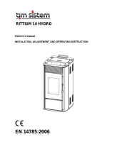
2.5.4 Primary Air Flow Sensor
It allows to detect the speed of the air flow in the air extraction pipe of the stove.
The range is 0 to 2000. In the case of disconnected probe will read a speed value of 0.
In the case of failed adjustment the message Er17 appears; in case of sensor failure or not properly
connected appears the message Er39.
You can use an Air Flow Sensor or a Differential Pressure Sensor.
If you use a Differential Pressure Sensor:
Install it horizontally through the mounting bracket supplied
The connections for the pressure reading (see the picture details 1 and 2) should be lowered. To
read connect to the P2 connector (see picture detail 2). Leave unconnected the P1 connector.
The connections with the control board are: 43=+12V (red wire), 44=SEG (yellow wire)
45=GND (black wire)
Legend:
1 Pressure Connection P1 (high pressure)
2 pressure Connect P2 (low pressure)
3 Electrical Connections

Pag. 10 / 44 DMAN802000066-Manuale SY250 Idro 4/8 tasti
3 Control Panel
Setting the parameter P50 it is possible to select the keyboard connected to the control board. If P50=0 is
selected the keyboard CP110 (4 keys), if P50=1 is selected the keyboard CP120 (8 keys).
ESC
G S W
L1
L5
L4
D2 D3
D1
P2P1
P4P3
L6 L7
L2 L3
CP110
ESC
L3
L2
L1
L8
L9
L10
L11
L4
D1
D2
D3
K1 K2 K3 K4
K8K7K6K5
SET
DISP
G S W
L12
L13 L5 LL6 L7
CP120
-Buttons
CP110
Click
Long Pressure
P1
Visualisations / Exit Menu
Ignition / Extinguishing / Block reset
P2
Thermostat modify (+) / Increase data
Pellet loading correction
P3
Combustion Power modify / Save data
Manual pellet loading
P4
Thermostat modify (-) / Decrease data
Combustion Fan speed correction
CP120
Click
Long Pressure
K1
Exit Menu
Ignition / Extinguishing / Block reset
K2
Combustion Power modify (+)
-
K3
Thermostat modify (+) / Increase data
Pellet loading correction
K4
-
Enable Chrono time slot
K5
Input User Menu 2 / Save data
Manual pellet loading
K6
Combustion Power modify (-)
-
K7
Thermostat modify (-) / Decrease data
Combustion Fan speed correction
K8
Visualisations
Summer / Winter choice
-Leds
L1
Led On: Pump On
L2
Led On: Auger On
L3
Led On: Ignition Resistance On
L4
Led On: thermostat temperature reached
L5
G
Led On: Daily program seleceted
L6
S
Led On: Weekly program seleceted
L7
W
Led On: Week End program seleceted
L8
Led On: Valve On
L9
Led On: lack of pellet in the tank
L10
Led On: Summer functioning selected
L11
Led On: Winter functioning selected
L12
Led On: Safety Pellet Valve or Auger 2, or External Loading Pellet Engine, or Cleaning
Engine On (only for Output V2)
L13
Led On: there is a sanitary water demand (contact closed).
Only for hydraulic systems with flow switch
-Control Panel Configuration:
Pushing at the same time the buttons P1/P3 or K1/K5 it is possible to choose the keyboard connected
to the control board without enter in System Menu.
-Values shown on the main frame:
Display D1: Time, Functioning States, Errors, Menu, Submenu, Parameter value;
Display D2: Power, Parameter code; Display D3: Main Temperature, Parameter code
-Functioning States:
Check Up (CHEc), Ignition (On 1, On 2, On 3, On 4), Stabilisation (On 5), Modulation (Mod), Standby
(StBY), Run Mode, Safety (SAF/Erxx), Extinguishing (OFF), Recover Ignition (rEc), Block (Alt/Erxx).

Pag. 11 / 44 DMAN802000066-SY250 Idro 4/8 Buttons Manual
-Errors:
Er01
Error Safety High Voltage 1. Also with the system Off
Er02
Error Safety High Voltage 2. Only if the Combustion Fan is On.
Er03
Extinguishing for exhaust under temperature
Er04
Extinguishing for water over temperature
Er05
Extinguishing for exhaust over temperature
Er07
Encoder Error. This error can occurs for lack of Encoder signal
Er08
Encoder Error. This error can occurs in case of adjustment problems of rounds number
Er09
Water pressure low
Er10
Water pressure high
Er11
Real time clock error
Er12
Extinguishing for Ignition failed
Er15
Lack of voltage
Er17
Air Flow Regulator Error
Er18
Run out of pellet
Er39
Air Flow Regulator Sensor broken
Er41
Minimum air flow in Check Up not reached
Er42
Maximum air flow Up reached (F40)
-Other messages:
Sond
Visualisation of the state of temperature probes. The message displayed in Check-Up
indicates that the red temperature on one or more probes is equal to the minimum value
(0°C) or maximum (it depend on probe considered). Check that the probes aren’t open (0°C)
or in short-circuit (maximum value of the temperature scale).
Hi
Boiler water temperature greater than 99 °C.
SErU
This message notifies that the planned hours of functioning (parameter T66) is reached. It is
necessary to call for service.
PULi
This message notifies that the planned hours of functioning (parameter T67) is reached. It is
necessary to clean the stove or boiler.
FLu
The message appears in Run Model and indicates that there is a sanitary water demand. (It
appears only for plumbing systems with a flow switch).
Ignition
Block
The message appears if the system is turned off during Ignition (after Preload) by an external
device: the system will stop only when it goes in Run Mode.
3.1 User Menu 1
-Boiler Thermostat:
Menu which allows to modify the Boiler Thermostat’s value. It is possible to program the minimum and
the maximum value of the Boiler Thermostat setting the Th26 and Th27 Thermostats.
-Visualisations:
tA
Control board room temperature (visible only if A19=1)
tP
Buffer temperature (visible only if P26=2, 3, 4)
tF
Exhaust temperature
UF
Combustion Fan speed [RPM/Volt]
FUnC
Funzionamento Modalità Summer (ESt)/Winter (InU)
FC
Firmware code and revision: FYSD01000114.00.00 (product without 2Ways)
FYSD01000102.00.00 (product with 2Ways)
395
Product Code: 0Y.0X
-Combustion Power Setting:
Click on P3 or K2/K6 button: the D2 display blinks. With other click of the same button the power is
changed. Ex.: 1–2–3–4–5–A (A=Automatic combustion). After 5 seconds the new value is saved and the
display shows as normal.
-Manual Pellet Loading:
The long pressure of button P3 or K5 activates the Pellet Manual Loading with activation of Auger
engine in continuous way. The bottom display shows the word LoAd, the up display shows the passed
loading time. To stop the loading push any button. The loading stops automatically after 300 seconds.
-Pellet Loading Correction:
The long pressure of P2 or K3 button activates this function. The bottom display shows PELL, the
upper display the value. With buttons P2/P4 or K3/K7 the value is increased or decreased. Values are

Pag. 12 / 44 DMAN802000066-SY250 Idro 4/8 Buttons Manual
between the range –7÷7; the default set is ‘0’. After 5 seconds the new value is saved and the display
shows as normal.
-Combustion Fan Correction:
The long pressure of P4 or K7 button activates this function. The bottom display shows UEnt, the
upper display the value. With buttons P2/P4 or K3/K7 the value is increased or decreased. Values are
between the range –7÷7; the default set is ‘0’. After 5 seconds the new value is saved and the display
shows as normal.
-Enable Chrono (only for CP120 control panel):
With the long pressure of K4 button it is possible to choice the Chrono Modality.
Daily Program
WG S
Weekly Program
WG S
Week-End Program
WG S
Chrono disabled
WG S
-Summer – Winter Modality (only for CP120 control panel):
With the long pressure of K8 button it is possible to modify the season.
3.2 User Menu 2
To enter in Menu:
CP110 control panel (4 buttons keyboard) push at the same time P3 and P4 buttons for 3 seconds
CP120 control panel (8 buttons keyboard) push the button K5
DISPLAY
DESCRIPTION
A i r
Menu to modify the heating power. It is visible only if P06=3 and P44=6.
T E r M
Menu to modify the Buffer Thermostat’s (Th58) and Room Thermostat’s value.
C r o n
ModE
Menu to select the Chrono’s program modality: Daily, Weekly, Week-End or
disabled. Only for CP110 control panel.
P r o G
Menu to program the time slots to switch on/off the system for each program
modality.
r i c E
Menu to select the Combustion Recipes. It is visible only if P04 is different to 1.
r E M
Menu to enable the Remote Keyboard’s Room Thermostat. It is visible only if
A52>0.
o r o L
Menu to set time and date.
FUnC
Menu to select the Winter or Summer modality. Only for CP110 control panel.
TELE
Menu to enable the Remote Control SYTX. Only for product without 2Ways.
LEAr
Menu to change the transmission code. Only for product with 2Ways.
3.2.1 Heating Power Menu
This Menu allows to manage the system’s heating in automatic or manual mode (in this case it is possible to
set the heating power). This Menu is visible only if P06=3 and P44=6.
Heating
Description
0FF
Heating Fan Off
1–Number of user power
Power manually set from 1 to Number of User Power (parameter
P03)
Auto
Heating Power set automatic by the system
3.2.2 Thermostats Menu
This Menu allow to modify the most important Thermostats used by the system.
Display
Thermostat
Description
AMb
Room
Menu to modify the Room Thermostat’s value. This Menu
appears only if A19=1.
PuFF
Buffer
Menu to modify the Buffer Thermostat’s value. This Menu is
visible only setting a plumbing system with a Buffer probe
(parameter P26=2, 3, 4).

Pag. 13 / 44 DMAN802000066-SY250 Idro 4/8 Buttons Manual
3.2.3 Chrono Menu
It allows to program the automatic ignition and extinguishing timer; it has 2 Submenu.
3.2.3.1. Enable Chrono Menu
This Menu is present only for product with the CP120 control panel and allows to select the chrono
modality. On display appears the label ModE.
MODALITY
LED
Gior: Daily Program
WG S
SEtt: Weekly Program
WG S
FiSE: Week-End Program
WG S
OFF: Programs Disabled
WG S
3.2.3.2. Programming Menu
On display appears the label ProG. It has 3 sugmenu, one for each program modality:
Daily: it allows to set 3 programs for each day of the week
Weekly: it allows to set 3 programs for all days of the week
Week-End: it allows to set 3 programs for Monday-Friday and 3 programs for Saturday-Sunday
VISUALISATIONS
DISPLAY
Daily Modality: the day
Mo
Weekly Modality: Monday-Sunday
MS
Week-End Modality: Monday-Friday
Saturday-Sunday
MF
S S
For On Timer is on the bottom segment on display D2
- - - -
1
I
Mo
For Off Timer is on the above segment on display D2
- - - -
1
I
Mo
Instructions
For each program it is necessary to set the time on and the time off.
DESCRIPTION
DISPLAY
1) Scroll with the buttons P2/P4 or K3/K7 until the wished Submenu
and push the button P3 or K5
G i o r n
2) Push the buttons P2/P4 or K3/K7 to select one of the 3 available
programs
- - - -
1
I
Mo
3) Push the button P1 or K4 for 3 seconds
0 0 . 0 0
1
I
Mo
4) Select the ignition time
5) Push the button P3 or K5 to enter in modify mode: the selected
value (hours or minutes) blinks. Push the button P3 or K5 to switch
between hours and minutes, P2/P4 o K3/K7 to modify the value.
0 1 . 0 0
1
I
Mo
6) Push the button P3 or K5 to save
2 1 . 3 0
1
I
Mo
7) Select with the button P2 or K3 the Off Timer and repeat the
procedure from point 5
0 0 . 0 0
1
I
Mo
For each time is possible to modify minutes with intervals of 15 minutes (e.g.: 20:00, 20:15, 20:30, 20:45).
Only for 11 p.m. is possible to increase minutes from 45 to 59, in order to get an ignition around midnight.
Program Chrono across Midnight:
Set for a programming time of a day of the week the time OFF at 23:59. Set the programming time of the
following day at the time of ON at 00:00.
Example:
Monday Program Chrono
ON
2 2 . 0 0
1
I
Mo
2 3 . 5 9
1
I
Mo
OFF
Tuesday Program Chrono
ON
0 0 . 0 0
1
I
Tu
0 7 . 0 0
1
I
Tu
OFF

Pag. 14 / 44 DMAN802000066-SY250 Idro 4/8 Buttons Manual
O
N
O
F
F
3.2.4 Combustion Recipe Menu
Menu to select the Combustion Recipe. The maximum value is the number of recipes visible to the user. This
value can be set in Default Settings Menu (parameter P04). If the parameter P04=1 the Menu isn’t visible.
3.2.5 Remote Keyboard Thermostat Enable Menu
Menu which allows to enable the Room Thermostat of the Remote Keyboard. It appears only if A52>0.
3.2.6 Time and Date Menu
This Menu allows to set time and date. The above display shows hour and minutes, the under display shows
the day of the week.
INSTRUCTIONS
DISPLAY
Push the button P3 or K5 to enter editing. The selected value (hours,
minutes, days) blinks. To change the value use the P2/P4 or K3/K7 button.
Push the button P3 or K5 to switch to modify the other parameters. Push
again P3 or K5 to save the set value.
0 7 . 3 3
Mo
3.2.7 Summer - Winter Menu
Menu to modify the plumbing system functioning according to the season. Only for CP120 control panel.
3.2.8 Remote Control Menu
This Menu allows to enable and disable the Remote Control SYTX. The system can manage a remote
controller that can communicate with the thermoregulator until 10 meters. Using the remote controller’s 4
buttons it is possible to switch on/off the thermoregulator and modify the functioning power.
The keys
Decrease/Increase Power
aren’t able to work if the combustion power is automatic. It is possible to
change the combustion power from Power 1 to Number of users power (parameter P03).
3.2.8.1. Change Code
The remote controller’s signal is recognized from controller board through a code (it is possible to change
the code using a Self learn procedure). For a correct transmission it is necessary that the remote controller
and the controller board have the same transmission code. Default code is 0, but if it is needed to change it,
follow the procedure below.
On the Remote Controller:
Open the battery box and move right the cover, modify the dip-switch’s configuration, close the
remote controller
On the Control Board
Switch off the power supply (230V)
Switch on the power supply pushing the same time one remote controller’s button
Wait (approximately 5 seconds) a controller board ‘s acoustic signal that confirms the new code.
3.2.9 Learn Menu
This Menu allows to the control board learning the 2Ways remote controller code. The default code is 1000;
if it is necessary to change code because problems of interference with other remote control, set the new
code into the Terminal Radio 2Ways Menu. When the remote controller 2Ways is ready to send the new
code, enter in the control board’s Learn Menu.
In the bottom display 4 lines blink. Wait for the message of the learning done ‘YES’. If the controller doesn’t
receive correctly the new code, the display shows the message “NO”. In this case repeat theoperation.
Off
On
Power increase
Power decrease

Pag. 15 / 44 DMAN802000066-SY250 Idro 4/8 Buttons Manual
3.3 System Menu
This menu allows to enter in the Technical Menu. On display appears the label tPAr. The access is protected
by password; the default password is “0000”. The menu of the product with radio control 2Ways
consists only of the Reset Counters Menu (tP11).
DISPLAY
DESCRIPTION
T P . 0 1
Auger Menu
T P . 0 2
Combustion Fan Menu
T P . 0 3
Heating Fan Menu
T P . 0 4
Thermostats Menu
T P . 0 5
Timer Menu
T P . 0 6
Default Settings Menu
T P . 0 7
Pressure Sensor Menu
T P . 0 8
Enables Menu
T P . 0 9
Temperature Delta Menu
T P . 1 1
Counters Menu
T P . 1 2
Outputs’ Test Menu
T P . 1 3
Extinguishing Thermostats Menu
T P 1 6
Air Flow Regulator Menu
T P 2 5
Combustion Fan 2 Menu
T P 2 6
Restore Default Values Menu
3.3.1 Auger Menu (TP01)
Menu that allows to set the Auger work time. The values are referred to the current combustion recipe
(selected in the User’s Menu); each value is a functioning power. If a value is set to 0 seconds the Auger is
disabled for the corresponding power. The Auger regulation can be set with a step of 0.1 seconds.
Code
Description
Min
Max
Unit
C01
Ignition Power
0
60
[s]
C02
Stabilisation Power
0
60
[s]
C03
Power 1
P27
60
[s]
C04
Power 2
P27
60
[s]
C05
Power 3
P27
60
[s]
C06
Power 4
P27
60
[s]
C07
Power 5
P27
60
[s]
C08
Power 6
P27
60
[s]
C09
Periodic Cleaning Power
0
60
[s]
C10
Second Ignition Power
0
60
[s]
C11
Modulation Power
P27
60
[s]
P05
Auger Period
4
60
[s]
P15
Calibration step of Auger work time
1
20
[%]
P27
Minimum work time
0
60
[s]
3.3.2 Combustion Fan Menu (TP02)
Menu to set the Combustion Fan’s values. They are referred to the current combustion recipe and each
value is a functioning power. In the encoder version (P25=1, 2) values are in revolutions per minute, in the
version without encoder (P25=0) they are in Volts. The set or calculated values are automatically define
between the limits P14 and P30.
Code
Description
Min
Max
Unit
U01
Ignition Power
0
230
[Volt]
300
2800
[RPM]
U02
Stabilisation Power
0
230
[Volt]
300
2800
[RPM]

Pag. 16 / 44 DMAN802000066-SY250 Idro 4/8 Buttons Manual
U03
Power 1
0
230
[Volt]
300
2800
[RPM]
U04
Power 2
0
230
[Volt]
300
2800
[RPM]
U05
Power 3
0
230
[Volt]
300
2800
[RPM]
U06
Power 4
0
230
[Volt]
300
2800
[RPM]
U07
Power 5
0
230
[Volt]
300
2800
[RPM]
U08
Power 6
0
230
[Volt]
300
2800
[RPM]
U09
Periodic Cleaning Power
0
230
[Volt]
300
2800
[RPM]
U10
Second Ignition Power
0
230
[Volt]
300
2800
[RPM]
U11
Modulation Power
0
230
[Volt]
300
2800
[RPM]
P23
Extinguishing Power
0
230
[Volt]
300
2800
[RPM]
P14
Minimum Speed of Combustion Fan
0
230
[Volt]
300
2800
[RPM]
P30
Maximum Speed of Combustion Fan
0
230
[Volt]
300
2800
[RPM]
P16
Calibration step of Combustion Fan
1
20
[%]
P25
0=Combustion Fan without Encoder; 1=Combustion Fan with
Encoder; 2=Combustion Fan with Encoder and automatic switch
to P25=0 if there is not encoder signal (alarm Er07)
0
2
[nr]
3.3.3 Heatingn Fan Menu (TP03)
Menu to set the Heating Fan parameters. Set these parameters if P44=6.
Code
Description
Min
Max
Unit
F01
Power 1
0
230
[Volt]
F02
Power 2
0
230
[Volt]
F03
Power 3
0
230
[Volt]
F04
Power 4
0
230
[Volt]
F05
Power 5
0
230
[Volt]
F06
Power 6
0
230
[Volt]
P06
Heating management: 1=heating power is the same of
combustion power; 2=heating power is proportional to the
exhaust temperature; 3=heating power is proportional to the
room temperature
1
3
[nr]
3.3.4 Thermostats Menu (TP04)
Code
Description
Min
Max
Unit
Th01
Stove off
5
900
[°C]
Th02
Resistance switch off
5
900
[°C]
Th03
Pre-Extinguishing thermostat for low flue gas temperature
5
900
[°C]
Th05
Switch on Heating Fan Thermostat
5
900
[°C]
Th06
Thermostat to go in Stabilisation from Variable Ignition
5
900
[°C]
Th07
Exhaust Modulation
5
900
[°C]
Th08
Exhaust Safety
5
900
[°C]
Th09
Bypass Ignition
5
900
[°C]
Th18
Ice Thermostat
5
10
[°C]
Th19
Activation Pump Thermostat
30
85
[°C]
Ih19
Activation Pump Thermostat Histeresys
1
20
[°C]
Th20
Sanitary 1 Thermostat
30
85
[°C]
Th21
Sanitary 2 Thermostat
30
85
[°C]

Pag. 17 / 44 DMAN802000066-SY250 Idro 4/8 Buttons Manual
Ih24
Water Boiler Thermostat Histeresys
1
20
[°C]
Th25
Boiler Safety Thermostat
80
99
[°C]
Th26
Boiler Thermostat minimum range
30
60
[°C]
Th27
Boiler Thermostat maximum range
60
95
[°C]
Th28
Exhaust Temperature control in Standby
5
900
[°C]
Ih33
Room Thermostat Histeresys
0
10
[°C]
Th56
Auxiliary Output Thermostat (if P48=3 or P44=3)
30
85
[°C]
Th57
Differential Thermostat Boiler Probe – Buffer Probe
1
30
[°C]
Ih57
Differential Thermostat Histeresys
1
5
[°C]
Ih58
Buffer Thermostat Histeresys
1
20
[°C]
3.3.5 Timers Menu (TP05)
Code
Description
Min
Max
Unit
T01
Check up cleaning time
0
900
[s]
T02
Preheating phase
0
900
[s]
T03
Auger Preload
0
900
[s]
T04
Fixed Ignition
1
3600
[s]
T05
Variable Ignition
1
3600
[s]
T06
Stabilisation
0
900
[s]
T07
Periodic cleaning cycle
15
600
[min]
T08
Periodic cleaning duration
0
900
[s]
T09
High Voltage 1 (Safety Thermostat) delay
1
900
[s]
T10
High Voltage 2 (Pressure switch) delay
1
900
[s]
T11
Exit from Standby delay
0
900
[s]
T12
Delay to increase the Pump Thermostat (Th19) in Step mode
functioning
0
10
[min]
T13
Minimum Period Time of Extinguishing
0
900
[s]
T14
Waiting time Pre-Extinguishing for no flame
0
900
[s]
T15
Waiting time Pre-Extinguishing in Safety
0
900
[s]
T16
Final Cleaning Time
0
900
[s]
T17
Delay time Combustion Power Change
0
900
[s]
T18
Delay time Combustion Power Change in exit from Ignition
0
900
[s]
T22
Delay time to enter in Standby
0
900
[s]
T23
Pellet tank charging time over minimum level (used if P44 or
P48=2)
0
9900
[s]
T24
Length signalling of fuel lack (if P44 and P48=1, 3, 4) or Pellet
tank charging time over minimum level (if P44 or P48=2)
0
3600
[s]
T27
Delay to disable Auger 2 (used if P44 or P48=1)
1
900
[s]
T30
Work time of Cleaning Engine (used if P44 or P48=4)
0
9600
[s]
T31
Wait time of Cleaning Engine (used if P44 or P48=4)
1
600
[min}
T40
Delay to enable Auger (used if P44 or P48=1)
0
900
[s]
T41
Work time of Pump
0
3600
[s]
T42
Maximum idle time of Pump
1
900
[ore]
T43
Delay to go in Standby from Modulation if boiler temperature >
(Boiler Thermostat+D23) and A13=1
0
3600
[s]
T46
Work time of Valve
0
3600
[s]
T66
Working time of the system before it goes in Block
0
9999
[ore]
T67
System’s working time before appears the message Cleaning
0
9999
[ore]
T68
Delay to restore the Boiler Thermostat’s value if there isn’t
sanitary request
0
900
[s]
3.3.6 Default Settings Menu (TP06)
Code
Description
Min
Max
Unit
P02
Maximum number ignition attempts
1
5
[nr]
P03
Work Combustion Powers’ number
1
6
[nr]
P04
Recipe number
1
4
[nr]
P09
Pellet Sensor configuration:
0=input N.C.; 1=input N.O.; 2=Sensor not used
0
2
[nr]
P20
Configuration of Pressure Boiler Water Sensor
0
2
[nr]

Pag. 18 / 44 DMAN802000066-SY250 Idro 4/8 Buttons Manual
P26
Plumbing system management
0
6
[nr]
P44
Output V2 management (pin 5-6):
0=Not used; 1=Safety Pellet Valve or Auger 2; 2=Load Pellet
Engine; 3=Output controlled by Thermostat; 4=Cleaning Engine;
5=Combustion Fan 2; 6=Heating Fan
0
6
[nr]
P48
Auxiliary Output management (pin 19-20-21):
0=Not used; 1=Safety Pellet Valve or Auger 2; 2=Load Pellet
Engine; 3=Output controlled by Thermostat; 4=Cleaning Engine
0
4
[nr]
P50
Local Panel Control selection (0=4 buttons keyboard; 1=8 buttons
keyboard)
0
1
[nr]
P66
Enable RS485
0
1
[nr]
3.3.7 Pressure Sensor Threshold Menu (TP07)
Code
Description
Min
Max
Unit
SP01
Minimum Pressure Sensor threshold
50
3000
[mbar]
SP08
Maximum Pressure Sensor threshold
50
3000
[mbar]
3.3.8 Enable Menu (TP08)
Code
Val.
Description
A01
(see
sec.
2.3)
0
Reached the Room Thermostat the system goes in Extinguishing
1
Reached the Room Thermostat the system goes in Modulation
2
Reached the Room Thermostat the system goes in Standby
3
Pump blocked (until water temperature<Th21 Thermostat)
A03
0
In Standby for Room Thermostat the Heating Fan is Off
1
In In Standby for Room Thermostat the Heating Fan goes at Power 1
A06
0
In Modulation the system uses Power 1: C03, U03
1
In Modulation the system uses Modulation Power: C11, U11
A08
0
During Ignition the Heating Fan is Off
1
During Ignition the Heating Fan is On
A10
0
From Extinguishing state it’s not possible to go directly to Ignition (first the system
goes into Recover Ignition and then goes into Ignition)
1
From Extinguishing state it’s possible to go directly to Check Up
A11
0
If room temperature is under Room Thermostat the Heating Fan is Off
1
If room temperature is over Room Thermostat the Heating Fan goes at Power 1
A13
0
Reached the Boiler Thermostat the system goes in Modulation
1
Reached the Boiler Thermostat the system goes in Modulation, then if water
temperature>(Boiler Thermostat+D23), at the end of T43, the system goes in
Standby
A14
0
Error Sensor Pressure disabled
1
Error Sensor Pressure enabled
A15
0
Pump works normally
1
Enable Step Pump management
A16
0
Disable delay time on power changing
1
Enable delay time on power changing
A19
0
Room Thermostat On/Off selected
1
Room Probe selected
A23
0
At end of Step Pump cycle, the Thermostat Th19 is at last calculate value
1
At end of Step Pump cycle, the Thermostat Th19 returns at default value
A26
0
The immediate exit from Standby is allowed
1
Exit from Standby is allowed after the timer T13 and if the Exhausting
Temperature<Th28 Thermostat
A28
0
Auger brake not activated
1
Auger brake activated
A29
0
If the system is in Standby for Room Thermostat or External Thermostat it doesn’t
exit if a sanitary water demand occurs
1
If the system is in Standby for Room Thermostat or External Thermostat it exits if a
sanitary water demand occurs

Pag. 19 / 44 DMAN802000066-SY250 Idro 4/8 Buttons Manual
A50
0
Modem management disabled
1
Modem management enabled
A52
0
Room Thermostat Menu of Remote Keyboard disabled
1
Reached the Room Thermostat the system goes in Modulation
2
Reached the Room Thermostat the system goes in Standby
3
Reached the Room Thermostat the system blocks the Pump until water temperature
< Th21 Thermostat
3.3.9 Temperature Delta Menu (TP09)
Code
Description
Min
Max
Unit
D01
Stabilisation Delta
0
100
[°C]
D04
Exhausting temperature delta for automatic management of
Heating Fan
10
120
[°C]
D05
Room temperature delta for automatic management of
Heating Fan
3
30
[°C]
D06
Increase of Th19 Thermostat if the Step mode functioning of
Pump is set
1
10
[°C]
D07
Water delta for final value of Thermostat if the Step mode
functioning of Pump is set
0
30
[°C]
D08
Water delta for power modulation in automatic combustion
management
1
30
[°C]
D23
Water Delta to add to the Boiler Thermostat to go in Standby
from Modulation at the end of T43 if A13=1
0
50
[°C]
3.3.10 Counters Menu (TP11)
Menu that allows the control of the counters useful for the diagnosis of the system’s life.
Submenu
Description
Co.01
Total time system feeding
Co.02
Activity time system: time at least one Fan works
Co.03
System real heating time: time in which heating is effectively produced (Run and
Modulation)
Co.04
Number of done ignition attempts
Co.05
Number of failed ignition attempts
Co.06
Number of errors occurred.
rES
Reset all counters: turn to zero all counters
The Counters Co.01, Co.02, Co.03 have the format:
The Counters Co.04, Co.05, Co.06 have the format:
The image shows a counter that indates 25
hour and 30 minutes.
253
0000
253
0000
Hundreds of hours
Tens of minutesTens of hours
Hours
The image shows a counter that indates 22324
occour events.
324
0022
324
0022
Thousand
UnitHundred
Tens

Pag. 20 / 44 DMAN802000066-SY250 Idro 4/8 Buttons Manual
3.3.11 Outputs Test Menu (TP12)
Menu that allows to test the Outputs (and the connected loading) with the system in Off state.
Submenu
Description
To.01
Auger Test
To.02
Output V2 Test
To.03
Combustion Fan Test
To.04
Heating Resistance Test
To.05
Pump Test
To.06
Valve Test
To.15
Auxiliary Output Test
The Outputs, if enabled, will stop after 30 seconds.
During the Combustion Fan Test, the display shows the set value [Volt] or [RPM] and the RPM of the fan
detected by the encoder (if is present): so it is possible to create a conversion table [RPM] / [Volt] to use for
the passage from encoder mode P25=1 to not encoder mode P25=0 in case of encoder breakage.
3.3.12 Extinguishing Thermostats Menu (TP13)
This Menu is the list of settings for each Combustion Power of the Exhausting Temperature under which,
after the Pre-Extinguishing time T14, the system goes in Extinguishing for no flame (Er03). These values
occur with the Th03 Thermostat.
Code
Description
Min
Max
Unit
Th35
Power 1
5
900
[°C]
Th36
Power 2
5
900
[°C]
Th37
Power 3
5
900
[°C]
Th38
Power 4
5
900
[°C]
Th39
Power 5
5
900
[°C]
Th40
Power 6
5
900
[°C]
Th43
Modulation Power
5
900
[°C]
3.3.13 Primary Air Flow Sensor Menu (TP16)
Menu to set the Air Flow Regulator parameters; all parameters are referred to the current recipe: it has 4
Submenu:
1. FL01 - Enables
Code
Description
Min
Max
Unit
A24
0=Regulator disabled; 1= Combustion Fan speed regulation;
2=Combustion fan speed regulation+Auger; 3=Auger On
time regulation; 4=Auger+Combustion fan speed regulation;
5=Air Flow Sensor not installed
0
5
[nr]
A25
0=Nothing to do if a regulation error occurs; 1=in case of
regulation error, the regulator has been reset and restart
regulation; 2=in case of regulation error the regulator is
disable
0
2
[nr]
A31
0=The regulator comes back on the last output; 1=The
regulator always works on the last output
0
1
[nr]
T19
Waiting time for stabilisation of regulation
5
900
[s]
T20
Waiting time for out of range regulator
10
900
[s]
T80
Waiting time for first regulation
0
900
[s]
2. FL02 - Air Flow Regulation Range
Code
Description
Min
Max
Unit
FL20
Minimum air flow in Check Up
0
2000
-
FL22
Minimum air flow for Power 1
0
2000
-
FL23
Minimum air flow for Power 2
0
2000
-
FL24
Minimum air flow for Power 3
0
2000
-
FL25
Minimum air flow for Power 4
0
2000
-
FL26
Minimum air flow for Power 5
0
2000
-
FL27
Minimum air flow for Power 6
0
2000
-
FL30
Minimum air flow for Modulation Power
0
2000
-
FL40
Maximum air flow
0
2000
-
/