Page is loading ...

© Bosch Automotive Service Solutions LLC
Form No. 529968
Parts List &
Operating Instructions
for: 5097
655 Eisenhower Drive
Owatonna, MN 55060 USA
Phone: (507) 455-7000
Tech. Serv.: (800) 533-6127
Fax: (800) 955-8329
Order Entry: (800) 533-6127
Fax: (800) 283-8665
International Sales: (507) 455-7223
Fax: (507) 455-7063
Transfer Tanker
Maintenance: Keep the reservoir
clean, and free of grit and grease.
Sheet No. 1 of 2
Issue Date: Rev. B, November 4, 2013
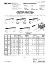
6,7
7,23 26
25
17,18,19
20
7,21,22
9
1
2
4
3
5
6,7
8
9
10
12
13 9,15,16
11
14
Bottom View with Straps
24

Item Part No.
No. No. Req'd Description
1 529967 1 Logo/Warning Decal
2 528090 4 Threaded Insert
3 528089 1 Oil Reservoir
4 210973 4 Swivel Caster (4")
5 528208 1 Handle Mount
6 11856 6 Round Head Machine Screw
7 207405 10 Hex Locknut
8 529966 1 Pump
9 12367 4 Hose Clamp (.68-1.25)
10 222685 1 Tubing
11 15997 1 Cotterless Hitch Pin
12 54555 1 Handle
13 18267 2 Handle Grip
14 207655 1 Cap
15 222682 1 Hose Fitting
16 222684 1 Fitting Cap
17 216260 3 ft. Air Hose
18 207201 1 Hose Fitting
(1/4 NPT F, 1/4 Barb)
19 12247 1 Quick-coupler Plug
20 210331 2 Hose Clamp
21 529109 1 Pump Bracket
22 10167 2 Round Head Machine Screw
23 10166 2 Machine Screw
24 531394 2 Front Plate
25 531395 2 Rear Plate
26 531396 2 Strap
Included But Not Shown
222693 1 Filter Screen
J-41329-10 4 Screw (#10 x 3/4 Long)
Parts List
Parts List & Operating Instructions Form No. 529968, Sheet 1 of 2, Back
Refer to any operating instructions included with the product for detailed information about operation, testing, disassembly,
reassembly, and preventive maintenance.
Items found in this parts list have been carefully tested and selected by OTC. Therefore: Use only OTC replacement
parts!
Additional questions can be directed to our Tech. Serv. Dept. at: 800-533-6127.
Safety Precautions
CAUTION: To prevent personal injury,
• Wear eye protection that meets ANSI Z87.1 and OSHA standards.
• Donottransportammable,volatileuids.Thetransfertankerhas
anelectricpump,whichcouldcauseareoranexplosion.

© Bosch Automotive Service Solutions LLC
Parts List & Operating Instructions Form No. 529968
AssemblyInstructions
(Refer to parts lists for item numbers in brackets.)
1. Mount the pump bracket to the handle mount using two screws (22) and locknuts (7).
2. From the top of the reservoir, install the four threaded inserts (see Figure A).
3. From the bottom of the reservoir, attach the handle mount (5) using the two front plates
(24) and two casters. Insert the caster studs through the large holes in the front plates
and through the slots in the handle mount. Install the caster studs into the front threaded
inserts (hand tighten only).
4. Attach a strap to each of the rear plates (25) using a screw (23) and a locknut (7). Note:
The direction of the screws must point away from the reservoir.
5. Insert the caster studs through the holes in the rear plates, and then install the caster
studs into the rear threaded inserts (hand tighten only).
6. Position the straps as shown in the illustration on Sheet 1 of 2. Attach the straps to the front plates using screws
(6) and locknuts (7). Note: The screws must be installed with the nut on the same side as the strap.
7. Mount the pump to the pump bracket using four screws (6) and locknuts (7).
8. Cuta14"pieceofhosefromthetubing(10),andinstallthehosebetweenthettingonthereservoirandthepump
inlet using two hose clamps (9).
9. Attachthehosettingandthequick-couplerplugtotheairhoseusingaclamp(20).
10. Clamp the air hose to the air inlet on the pump using a hose clamp (20) (see Figure B).
11. Install the cap (14) and grips (13) to the handle. Attach the handle to the handle mount using the cotterless hitch
pin (11).
12. Attach the remaining hose to the outlet side of the pump with a hose clamp (9).
13.Attachthehosetting(15)tothehosewithahoseclamp(9),andinstallthettingcap(16)(seeFigureA).Wrap
the hoses around the handle ears leaving slack to enable handle movement without damaging the hoses.
14. Attach the screen to the reservoir by installing a self-tapping screw through a hole in each corner of the screen.
Figure B
Sheet No. 2 of 2
Issue Date: Rev. B, November 4, 2013
Place locknut on
this side of plate.
Rear Caster /
Plate
Pump
Use Clamps
(9) to hold
hose in place.
14" Hose
Hose Fitting (18), Quick-
coupler Plug (19), Air
Hose (17), and Clamp (20)
assembly
Attach Pump
Bracket (21)
to Mounting
Bracket (5).
MountingBracket
Air Hose
(Wrap loosely
around ears.)
Threaded Inserts
(Thread casters to
inserts.)
Threaded
Inserts
Fitting (15), Clamp
(9), and Cap (16)
Figure A
/