
Sheet 1 of 7
581187 Rev D
PROPULSION COMPONENT LIFT
Maximum Capacity: 800 kg (1760 lbs.)
Description:
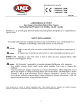
This lift is uniquely designed for removal and installation of electric vehicle batteries.
This product can also be used for removal and installation of various other
components, such as: engines, transaxles, fuel tanks, suspensions, cradles, chassis
system components, and future powertrains.
Parts List and
Operating Instructions for: 5295
Form No. 581187
655 Eisenhower Drive
Owatonna, MN 55060 USA
Phone: (507) 455-7000
Tech. Serv.: (800) 533-6127
Fax: (800) 955-8329
Order Entry: (800) 533-6127
Fax: (800) 283-8665
International Sales: (507) 455-7223
Fax: (507) 455-7063
© Bosch Automotive Service Solutions Inc.

Back Sheet 1 of 7
Safety Precautions
WARNING: To prevent personal injury or equipment damage,
●Study, understand, and follow all instructions before operating this device.
●Wear eye protection that meets OSHA and ANSI Z87.1 standards.
●Only qualified personnel shall perform inspections and repairs to this lift.
●Before using lift, inspect the lift for bends, cracks, dents, elongated holes, or missing
hardware. If damage is found, discontinue use.
●Use only those repair parts called out in the parts list in this document. Items found
in the parts list have been carefully tested and selected.
●Do not exceed the rated capacity of lift or platform extension.
●Do not raise or lower lift with platform extended.
●Use only on a hard, level surface.
●Do not raise or move a load having a center of gravity extending beyond the wheels.
Tipping can result in personal injury.
●Do not move lift while a load is raised. Carefully and slowly move the load on inclines
or around corners. Tipping can result in personal injury. Lower load completely before
storage.
●Do not stand under a load supported by the lift.
●Secure component in place before removing it from the lift.
●No alterations shall be made to this product as this will void the warranty.
Pump
●Do not exceed the hydraulic pressure rating noted on the pump data plate or tamper
with the internal high pressure relief valve. Creating pressure beyond the rated
pressure can result in personal injury.
●Before replenishing the fluid level, retract the system to prevent overfilling the pump
reservoir. An overfill can cause personal injury due to excess reservoir pressure
created when cylinders are retracted.
Explanation of Safety Signal Words
The safety signal word designates the degree or level of hazard seriousness.
DANGER: Indicates an imminently hazardous situation which, if not avoided, will result in death or
serious injury.
WARNING: Indicates a potentially hazardous situation which, if not avoided, could result in death or
serious injury.
CAUTION: Indicates a potentially hazardous situation which, if not avoided, may result in minor or
moderate injury.
CAUTION: Used without the safety alert symbol indicates a potentially hazardous situation which, if not avoided,
may result in property damage.

Sheet 2 of 7
Preparation and Set Up
Unpackaging
1. Cut shipping banding from carton and platform.
2. Install lift handle into base frame weldment and secure in place with cotterless hitch pins.
3. Remove the wood chocks from around the caster wheels.
4. Carefully roll the lift off the shipping pallet onto the floor.
Prepare The Air Pump For Operation
A. Pictogram Definitions
B. Cut shipping tie straps from air pump.
C. Air Supply Hook Up
1. Remove the thread protector from the air inlet of the pump. The pump's air inlet is 1/4-18 NPT
internal threads. Select and install the threaded fittings which are compatible with your air supply
fittings. The air supply should be 20 CFM (.57 M³/min.) at 100 PSI (7 BAR) at the pump to obtain
the rated hydraulic pressure. Air pressure should be regulated to between 50 PSI (3.5 BAR) and
140 PSI (9.5 BAR). A pressure of 100 PSI (7 BAR) is the recommended minimum. Secure your
pump fitting to the air supply.
2. It is highly recommended to install an automatic air line oiler to the air supply as close to the pump
as possible. Set the unit to feed approximately one drop of oil per minute into the system. Use SAE
grade oil, 5W to 30W.
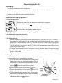
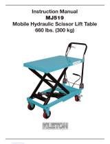
D. Priming The Pump Unit
Under certain circumstances it may be necessary to prime the air pump.
To accomplish this, perform the following procedure:
1. Press the release end of the pedal while holding down
the air intake valve with a flathead screwdriver. The air
intake valve is located directly under the pedal in the area
marked . The valve is depressed simultaneously
with the area of the pedal during priming.
2. Allow the pump to cycle approximately 15 seconds.
3. Remove the screwdriver and press the end of the
pedal once more.
4. If the cylinder extends or pressure builds, the pump has
been successfully primed. If the pump does not respond,
repeat the procedure, jogging the air intake valve while
holding the pedal in the position.
Activating the pump with the pedal end marked with this pictogram,
the flow of fluids is directed out of the reservoir.
Activating the pump with the pedal end marked with this pictogram,
the flow of fluids is directed back to the reservoir.
Air
Intake
Valve
Filler/
Vent
Cap
Air Inlet
(1/4-18 NPT
internal)

Back Sheet 2 of 7
Functional Check of Lift
Without external load applied to lift platform, fully raise and lower multiple times to ensure proper function of
the hydraulic system and scissor components.
1. Press the end of the air pump foot pedal marked to raise the lift platform until it stops at maximum
extension.
2. Press and hold the end of the air pump foot pedal marked to lower the lift platform until it reaches
full collapse.
3. Ensure platform raises and lowers only when the air pump foot pedal is actively depressed by the operator.
WARNING: To prevent personal injury and/or equipment damage, if platform moves after air
pump pedal is released, discontinue use and service immediately.
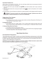
Preparation of Other Features
A. Platform Tilting Features
1. Turn forcing screws in/out fully to ensure proper function of platform tilting feature. See Figure 1 of
“Fine Adjustment Tilting Feature” section.
B. Stabilization Feature
1. Insert leveler screws into sockets (approx. 5 turns). Leveler screws should not project above steel
tube or contact platform underside when not in use. See Figure 2 of “Stabilization Feature” section.
C. Platform Sliding Extension Feature
1. Cut shipping banding securing platform halves
2. Retract spring plunger and extend platform by pulling on table handle. Ensure spring plunger engages
at all three stop positions when the plunger is released.
Operating Instructions
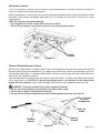
Fine Adjustment Tilting Feature
The forcing screws shown in Figure 1 allow the user to finely tilt the platform to help remove or install vehicle
components. This feature provides a total of two inches of tilt at the front of the platform which helps compensate
for uneven shop floors, difficult fastener locations, etc. The forcing screws can be operated by either hand, or
wrench or socket, depending on the applied load.
CAUTION: To prevent equipment damage, do not tilt the platform without the leveler screws in their
lowest position as the platform might be driven into the screws.
Figure 1
Forcing
Screws

Sheet 3 of 7
Figure 2
Leveler
Screws
Stabilization Feature
If lift is to be used as a stationary work surface for servicing components, two leveler screws (see Figure 2)
have been added to help stabilize the platform.
When the desired tilt or platform position has been reached, thread both leveler screws inward until they meet
the bottom of the platform and tighten finger-tight only. This provides two extra points of contact for a more
stable platform.
CAUTION: To prevent equipment damage,
• Do not tighten the leveler screws with a wrench or ratchet.
• Do not tilt the platform if the leveler screws are not in their lowest position.
Platform Sliding Extension Feature
When the lift is to be used as a stationary work surface, the sliding platform extension may be used to facilitate
the separation of powertrain components (i.e., engine and transmission). Retract spring plunger and pull on
Table Handle (See Figure 3) to extend sliding platform. Release spring plunger and slide platform extension
until it locks into a stationary position.
Secure components to the platform with bolts and/or straps. Many M10 x 1.5 holes are provided in the platform
top to thread bolts into. CAUTION: To prevent damaging threads in the platform, do not torque bolts
beyond 50 ft. lbs. (68 N•m). Holes in the side edges of the platform are provided for securing straps.
WARNING: To prevent personal injury and/or equipment damage,
●Always secure components to the platform with bolts and/or straps.
●Do not raise or lower lift with platform extended.
●Do not use the Platform Handle (located on the sliding platform) to move the entire lift.
Figure 3
Platform
Handle
Spring
Plunger
M10 x 1.5 holes
to secure
components
Holes for
straps

Back Sheet 3 of 7
Operating The Lift To Remove Components
1. Always follow the vehicle manufacturer’s recommended service procedure for removal of the component.
2. Position the lift under the vehicle. Connect the air hose to the air pump.
3. Press the end of air pump foot pedal marked to raise the lift to the load.
4. Remove any remaining bolts from the vehicle component.
5. Press the end of the air pump foot pedal marked and lower the lift completely.
6. Move the lift and load out from under the vehicle.
Operating The Lift To Install Components
1. Position the lift under the vehicle chassis.
2. Align the component in the correct position and press the end of the air pump foot pedal marked to
raise the lift.
3. Always follow the vehicle manufacturer’s recommended service procedure for installing the component.
Inspection and Maintenance
CAUTION: To prevent personal injury,
• Only qualified personnel shall perform inspections and repairs to this lift.
• Before each use, inspect the lift for bends, cracks, dents, elongated holes, or missing hardware. If
damage is found, discontinue use.
• Use only those repair parts called out in the parts list in this document. Items found in the parts
list have been carefully tested and selected.
Inspection
Before each use, an approved inspector must inspect the lift for bends, cracks, dents, elongated holes, or
missing hardware. If damage is found, discontinue use.
Repair
When repairing the lift, use only those repair parts called out in the parts list in this document. Items found
in the parts list have been carefully tested and selected.
Disposal
At the end of the useful life of the lift, dispose of the components according to all state, federal, and local
regulations.
Preventive Maintenance
NOTE: 1 cycle = 1 complete raising and lowering of the lift platform.
Every 300 cycles or 6 months, whichever comes first:
A. Hydraulic Cylinder
1. Inspect for hydraulic fluid leaks.
●Some oil accumulation on cylinder rod is normal and desired for proper function of the unit.
●If fluid is escaping and puddling on the floor, the cylinder requires servicing.
2. Without load applied to platform, raise and lower lift multiple times. If cylinder pulses, sticks, or
generally doesn't operate smoothly, unit needs servicing.

Sheet 4 of 7
Preventive Maintenance continued
B. Hydraulic Fittings
1. Inspect for leaks.
●Tighten fittings to stop leak.
●Replace fittings if tightening does not stop leak.
C. Hose
1. Inspect and replace if found to contain cuts, cracks, or considerable surface wear.
D. Pump
1. Check hydraulic fluid level.
●The fluid level should be 1/2 inch (12.7 mm) from the filler/vent cap with cylinder retracted.
Replenish with hydraulic fluid (P/N 9637) through this port if needed.
2. Check pump reservoir for leaks due to damage to reservoir.
3. Raise and lower platform by operating air pump pedal. Ensure platform raises and lowers only when
the air pump pedal is actuated.
WARNING: To prevent personal injury and/or equipment damage, discontinue use and
service the unit immediately if platform moves after air pump pedal is released.
4. If platform moves slowly when raising, or pump seems to reciprocate faster than normal, install an
automatic air line oiler prior to the pump.
●When automatic air line oiler is installed, some oil discharge from pump exhaust is normal and
indicates proper lubrication.
E. Lubrication
1. Use a grease gun to thoroughly apply grease at every location fitted with grease fitting (i.e., upper
& lower rollers, casters, scissor & hydraulic cylinder pivot pins, etc.). Pump grease into fitting until
only new grease can be seen escaping from joint. Wipe away excess.
F. Cleaning
1. Wipe dirt, debris, and grime from all surfaces using clean rag.
Every 3000 cycles or 24 months, whichever comes first:
A. Draining and Flushing the Pump Reservoir
1. Remove screws that fasten pump assembly to reservoir. Remove pump assembly from reservoir.
Do not damage gasket, filter or safety valve.
2. Drain reservoir of all fluid and refill half full with clean hydraulic fluid (P/N 9637). Rinse filter clean.
3. Place pump assembly back onto reservoir, and secure with two machine screws assembled in
opposite corners of housing.
4. Run unit for several minutes. Use same method described in section titled “Priming the Pump Unit.”
5. Drain and clean reservoir once more.
6. Refill reservoir with hydraulic fluid (p/n 9637) and replace pump assembly (with gasket) on reservoir
and install screws. Torque screws to 25 to 30 inch pounds (2.8 to 3.4 N•m).
B. Refilling the Pump Reservoir
1. If additional fluid must be added to reservoir, use only hydraulic fluid (p/n 9637; 215 SSU @ 100°
F [38° C]). Clean entire area around filler plug before adding fluid to reservoir. Remove filler plug,
and insert a clean funnel with filter. The cylinder must be fully retracted and air supply disconnected
when adding fluid to reservoir.

Back Sheet 4 of 7
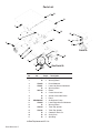
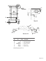
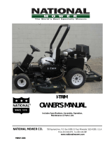
Parts List
Item Part No.
No. No. Req'd Description
1 Ý 2 Warning Decal
2 Ý 2 Warning Decal
3 579255 1 Base Weldment
4 579251 1 Lower Left Scissor Weldment
5 Ý8 Warning Decal
6 564118 1 Elbow
7 Ý4 Caster Swivel Lock
8 Ý4 Swivel Caster With Brake
9 Ý1 Decal
10 SP04506444 1 Air/Hydraulic Pump
11 579254 1 Lower Right Scissor Weldment
12 Ý 1 Warning Decal
13 579134 1 Table Top, Split40
14 579136 1 Table Top, Split60
15 Ý2 Cotterless Hitch Pin
16 Ý14" Sash Chain
17 Ý2 Split Ring
Ý See Replacement Kit List
1
3
2
4
5
6
7
8
9
10
11
12
13
14
15
See Detail A
Detail A
16
17

Sheet 5 of 7
U
U
130°
120°
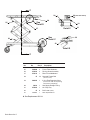
Item Part No.
No. No. Req'd Description
18 Ý 4 Eccentric Guide
19 Ý 4 Hex Head Cap Screw
20 579131 1 Table Top Weldment
21 SP045064341 Hydraulic Cylinder
22 564117 1 Velocity Fuse
23 5792591 Hydraulic Hose
Ý See Replacement Kit List
14
18
19
20
21
22, 23
Detail B
See
Detail B
Section U-U
U
U

Back Sheet 5 of 7
Item Part No.
No. No. Req'd Description
24 578891 1 Riser Frame Weldment
25 564060 2 Frame Tube Weldment
26 579553 2 Forcing Screw Assembly
27 579152 1 Riser Frame Weldment
28 Ý18 Serrated Flange Bolt
(3/8-16 x 3/4")
29 566055 1 In-line Flow Regulator Valve
(Install valve with arrow pointing
towards the pump body.)
30 10623 1 Hex Nipple Straight Fitting
31 579264 1 Air Pump Tray
32 Ý8 Ball Caster (.625")
33 579131 1 Table Top Weldment
Ý See Replacement Kit List
See
Detail D
See
Detail C
Detail C
(See note below)
Detail D
24
25
26
27
28 29,
30
10
31
32
Z
Z
33

Sheet 6 of 7
See
Detail E
See
Detail F
See
Detail G
See
Detail H
Detail E
Detail F Detail G Detail H
34
35
36 37
35
38
39
27
24
25
40
38
4
38
3
34
21
41 41
42
3
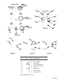
Item Part No.
No. No. Req'd Description
34 579188 4 Roller
35 Ý 13 Retaining Ring
36 579257 2 Table Keeper
37 578798 1 Table Base Weldment
38 Ý16 Grease Fitting (Alemite)
39 Ý6 Pivot Pin
40 564076 8 Hex Lock Nut
41 Ý5 Retaining Ring
42 Ý2 Cylinder Pivot Pin
Ý See Replacement Kit List
Section Z-Z

Back Sheet 6 of 7
See
Detail J
Detail J
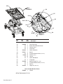
Item Part No.
No. No. Req'd Description
43 579126 1 Table Handle
44 578940 1 Table Top Hinge
45 Ý 2 Socket Head Shoulder Screw
46 Ý 2 Locknut (Nylon)
47 Ý 2 Cap Screw
48 579012 2 Center Guide Bar
49 5790112 Spacer
50 Ý 6 Flat Head Socket Screw (.313-18)
51 1023010 Washer (5/16")
52 Ý 10 Locknut
53 Ý 3 Center Rod Mount
54 Ý 2 Flange Nut
55 579768 1 Spring Plunger Pin (.375")
56 Ý 4 Flat Head Socket Screw (.313-18)
57 Ý 2 Roll Pin
58 2164321 Hinge Nut (.625"-18)
Parts Included But Not Shown
578896 1 Handle
Ý See Replacement Kit List
43
58
44
45, 46
47
48
50, 51, 52
53
55
56
57
49
54

Sheet 7 of 7
Replacement Kit List
Item
No. Qty. Description
579905 Chain, Pin, Ring Kit
15 2 Cotterless Hitch Pin
16 14" Sash Chain
17 2 Split Ring
579906 Pivot Pin Hardware Kit
35 4 Retaining Ring
38 2 Grease Fitting (Alemite)
39 2 Pivot Pin
579907 Hardware Kit
45 2 Socket Head Shoulder Screw
46 2 Locknut (Nylon)
47 2 Cap Screw
50 6 Flat Head Socket Screw (.313-18)
52 10 Locknut
54 2 Flange Nut
57 2 Roll Pin
579908 Guide Kit
18 4 Eccentric Guide
19 4 Hex Head Cap Screw
Item
No. Qty. Description
579909 Decal Kit
1 2 Warning Decal
2 2 Warning Decal
5 8 Warning Decal
9 1 Decal
12 1 Warning Decal
579910 Cylinder Pin Hardware Kit
41 4 Retaining Ring
42 2 Cylinder Pivot Pin
579911 Center Mount Pack
53 3 Center Rod Mount
579912 Caster Kit
7 1 Caster Swivel Lock
8 1 Swivel Caster With Brake
579913 Bolt Pack
28 6 Serrated Flange Bolt (3/8-16 x 3/4")
579915 Ball Caster Pack
32 4 Ball Caster (.625")
IMPORTANT PRODUCT INFORMATION
Record serial number and year of manufacture for future reference. See product identification
label on unit for information.
Serial Number: Year of Manufacture:
Get parts at OTCparts.com
This document contains product parts lists and information regarding
operation and maintenance. Items listed in the parts list have been carefully
tested and selected by OTC. Therefore, use only OTC replacement parts.
Product questions may be directed to the OTC Technical Service Department
at (800) 533-6127.
-
 1
1
-
 2
2
-
 3
3
-
 4
4
-
 5
5
-
 6
6
-
 7
7
-
 8
8
-
 9
9
-
 10
10
-
 11
11
-
 12
12
-
 13
13


Ask a question and I''ll find the answer in the document
Finding information in a document is now easier with AI
Related papers
-
OTC 1778B Operating instructions
-
-
-
-
-
-
-
-
-
Other documents
-
 AME International 15920 Owner's manual
-
 Kleton MJ519 User manual
-
Vestil CART-1100-SS Owner's manual
-
 Scag Power Equipment Cheetah SCZ48V-23CV User manual
-
Maxon GPT SERIES (2005 Release, After October 1, 2005) Maintenance Manual
-
-
-
-
 Scag Power Equipment Cheetah II User manual
-
 National Mower I-TRIM Owner's manual


