Page is loading ...

X1 SERIES ELEVATOR
CONTROLLER PCB ONLY
Quick Start Guide
LT-2466 21293 © 2021 Digital Monitoring Products, Inc.
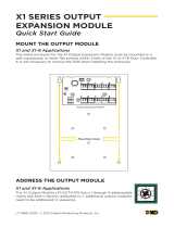
MOUNT THE PCB ONTO THE ENCLOSURE
The metal enclosure for the X1 Elevator Control Expansion Module (X1-ELEV-EXP)
comes with mounting holes for two additional X1 Elevator Control Module PCBs
(X1-ELEV-PCB). To mount the additional PCB, use the provided standos and
screw the PCB onto the 3 mounting holes.
0
1
2
3
4
5
6
7
8
9
Second X1 Elevator Module
0
1
2
3
4
5
6
7
8
9
Third X1 Elevator Module
Standos (3)
X1 Elevator Expansion
Screws (3)
SET THE ADDRESS
The X1 Elevator Control Module PCB (X1-ELEV-PCB) has a 1 through
9 addressable rotary dial that is factory defaulted to 1. Additional
elevator control modules need to be addressed in sequence.
PRE-INSTALLATION
Warning: This elevator control module can not be installed without being
in contact with the elevator service company. This guide covers only what
the elevator control installer will be able to do.
0
1
2
3
4
5
6
7
8
9
Second X1 Elevator Module
0
1
2
3
4
5
6
7
8
9
Third X1 Elevator Module
Standos (3)
X1 Elevator Expansion
Screws (3)

X1 ELEVATOR CONTROL MODULE PCB ONLY | DIGITAL MONITORING PRODUCTS 2
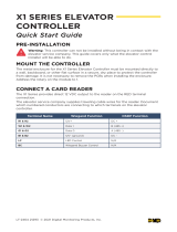
WIRE THE X1 ELEVATOR CONTROL MODULE PCB
TO THE EXPANSION MODULE
Use the included 4-position harness to connect the top connector on the third
elevator control module to the bottom connector on the second elevator control
module.
0
1
2
3
4
5
6
7
8
9
First X1 Elevator Module
X1 Elevator Controller
12 V Battery
+ -
-
+
0
1
2
3
4
5
6
7
8
9
Second X1 Elevator Module
0
1
2
3
4
5
6
7
8
9
Third X1 Elevator Module
X1 Elevator Controller X1 Elevator Expansion

3 X1 ELEVATOR CONTROL MODULE PCB ONLY | DIGITAL MONITORING PRODUCTS
WIRE FOR FLOOR ACCESS
The X1 Series Elevator Control Module provides 10 Form C (SPDT) 1 Amp relays
for controlling access to 10 floors. The three relay terminals are labeled for
normally open (NO) and normally closed (NC) operation. The center terminal is
the common. See figures. These allow you to connect the device wiring to the
relay for floor access control.
Warning: Before wiring for floor access, check with elevator service
company for their desired relay operation for controlling the floors.
1. Wire the number of controlled floors to the elevator control module. To
wire for floor access control, use the 10 terminals on the elevator control
module and label them carefully for the elevator service company.
2. Allow extra wire so that the elevator service company has enough length
to attach to the elevator control center.
3. Ensure the wires are in a logical location for the elevator service
technician to find.
NC 1 NO
Normally Open
Common
Normally Closed
PWR
DATA
0
1
2
3
4
5
6
7
8
9
ADDR
6
1
7 8 9 10
2 3 4 5
NC 1 NO NC 2 NO NC 3 NO NC 4 NO NC 5 NO
NC 6 NO NC 7 NO NC 8 NO NC 9 NO NC 10 NO
NC 1 NO NC 1 NO
Normally Open Normally Closed
Top 4-Wire Connector
to X1 Elevator Controller
X1 Elevator Module

More Information
Designed, engineered, and manufactured in Springfield, Missouri
.
INTRUSION • FIRE • ACCESS • NETWORKS
2500 North Partnership Boulevard Springfield, Missouri 65803-8877
800.641.4282 | dmp.com
|
Follow the QR code for the full Installation and
Programming Guide.
PROGRAM IN DEALER ADMIN™
Go to Dealer Admin (dealer.securecomwireless.com) to program the elevator
control module.
TEST THE CONTROLLER
Make sure that the Reader LEDs are on and the elevator controller’s power LED
is on. If connected to Wi-Fi, the Wi-Fi LED is on solid. If connected to network,
the Network Port light is blinking. For cell and all communication methods, check
that the elevator controller is communicating with Dealer Admin and Virtual
Keypad after Dealer Admin programming is completed.
The elevator control modules each have ten onboard LEDs per floor relay. For
visual confirmation of the relay operation, the LEDs are on when the relay is on
and o when the relay is o.
/