Ender 3 E 3D Printer User manual

Category
3D printers
Type
User manual

This manual is also suitable for

Ender 3 E 3D Printer: Experience limitless creativity with precise FDM modeling capabilities, crafting objects up to 220 x 220 x 250mm. Achieve intricate details with 0.1mm layer height resolution and 0.4mm nozzle diameter. Explore a wide range of compatible filaments, including PLA, to bring your designs to life.

Ender 3 E 3D Printer: Experience limitless creativity with precise FDM modeling capabilities, crafting objects up to 220 x 220 x 250mm. Achieve intricate details with 0.1mm layer height resolution and 0.4mm nozzle diameter. Explore a wide range of compatible filaments, including PLA, to bring your designs to life.

V1.2
3D Printer User Manual
Ender-3 E
To further improve your user experience, Please watch the Assembe
& Tutorial Video in the TF card provided with the printer.
Instructions for Use
CREALITY Ender 3 E 3D Printer comes with 1-year warranty of accessories
repair and accessories replacement.
All customers' questions or problems with the machine come first.
Any question or problem, be free to contact our store seller directly. Thank
you.
We do not recommend you to contact the official website, Usually, they only
respond to general product inquiries.
List of Accessory Kit Items:
Wrench and
Screwdriver X 1
Blade X 1
18 Cutting
Pliers X 1
19 Filament X 1
21
Pneumatic
Connector X 2
20 22
Base Frame Package
X 1
Print hea Kit X 1 Power Supply
Module X 1
Material Barrel
X 1
Z-axis Passive
slider X 1
Display Screen X 1
15
6 7 8 Extrusion Kit X 1 X belt adjuster
X 1
9Z-axis motor
X 1
10
23 4 ZScrew Rod X 1
15 16 17
Z-axis Right Profile X 1 Z-axis Left Profile X 1 X-axis Profile X 1
Rack X 1
11 20 Profile End
Cap X 2
12 13 Belt X 1 14 Top Gantry Profile X 1
List of Main Parts:
Power Cord X 1
30 Nozzle Cleaner
X 1
31 Cable Tie X 5
32 Memory Card and
Card Reader X 1
33 Nozzle X 1
34
Printer Port Instructions
Mainboard Port Instructions
Note: The components above are for reference only. The actual product may vary.
M5x25 Socket Head
Cap Screw with Spring
Washer X 4
26 M4x20 Hexagon
Flat Round Head
Screw X 2
27 M5x45 Socket
Head Cap Screw
with Spring Washer X 4
28 M5 Ship-type
Nut X 2
29
M5x8 Hexagon Socket
Flat Head Screw X 4
23 M4x16 Socket Head Cap
Screw with Spring Washer X 4
24 M4x18 Hexagon socket
countersunk head screw X 2
25
TF
X-Axis Motor Port
Controllable
fan port
Micro USB interface
Display port
Printhead thermistor
interface
Hot bed thermistor
interface
Reserved port of
BL&CR_TOUCH
Normal fan
port
Cable port
for hot bed
Cable port
for printhead
Filament
Sensor
port
X-axis
Limit
Switch
Port
Y-axis
Limit
Switch
Port
Z-axis
Limit
Switch
Port
Y-Axis Motor Port Z-Axis Motor Port Extrusion Motor Port TF Card Slot
Fuse
Power input
jack
Assemble the printer
Short
Short
Left
Front
Right
Behind
inside
inside
M5x45
long
1.Install Z-axis profiles left and right
2.Install the display screen and power supply
Please leave a gap
M4x20
M5x8
3.Install the Z-axis motor and Z Screw rod
Note: When installing the Screw Rod, keep it vertical
Install the Z screw rod
and tighten the screw
Install the Z motor
M4x18
vertical center
4.Assemble the X-axis kit
large screw hole large screw hole
Front
short
Behind
Long
M4X16
M4X16
Z-axis passive slider
Extrusion Kit
Print head kit
X-axis Prole
Left Right
5.Install the X-axis kit and top gantry profile
Rotate z-axis screw rod and press down
large screw hole
20 Prole End Cap
Embed the Ship-type Nut
Assembling the Filament Rack
Pre-installed boat nuts
Don't tighten for now
Tighten the screws
M5x8
6.Install the filament rack
Behind
Front
7.Install the X-axis belt and belt adjuster
Pre-installed
boat nuts
Install the
belt adjuster,
Don't screw it
for now
Adjust belt
and tighten
screws
Usually the Y motor and Y-axis limit switch cables are
already installed, Please check to confirm.
Note: Adjust the voltage properly according to your region
before plugging in the power cord, and turn on the machine
only after the voltage is correct.
8. Install X, Z, E Motor Cables and Limit Switch Cables
Filament sensor interface
E motor interface
X motor interface
Y motor interface Z motor interface
X-axis limit switch
interface
X
Z
E
Y
motherboard
Power interface
Display screen interface
EXP3
Voltage switch
Leveling Bed
Info Screen
Motion
Temperature
Configuration
Change Filament
Info Screen
Motion
Temperature
Configuration
Change Filament
Preheat PLA Conf
Preheat ABS Conf
Store Settings
Load Settings
Restore Defaults
Probe Z Offset:
-0.04
-0.02
0.00
0.02
0.04
Preheat PLA Conf
Preheat ABS Conf
Store Settings
Load Settings
Restore Defaults
Probe Z Offset:
-0.04
-0.02
0.00
0.02
0.04
Main
Move Axis
Auto Home
Level Bed
Proble Z Offset
Main
Move Axis
Auto Home
Level Bed
Proble Z Offset
Info Screen
Pause Print
Stop Print
Tune
About Printer
Bed: 50
0%
100
Fan Speed:
Flow:
Probe Z Offset
Store Settings
Bed: 50
0%
100
Fan Speed:
Flow:
Probe Z Oset
Store Settings
Preheat PLA Conf
Preheat ABS Conf
Store Settings
Load Settings
Restore Defaults
1. Before leveling the bed, Please select Restore Default settings and
select Store Settings.(Save Settings)
Wait for the probe
to end
2.Select Level Bed and select Proble Z Offset to adjust the first layer print
height.
make sure the distance between nozzle and platform is about the thickness
of an A4 sheet of paper, Then click Store settings.
3.When printing, you can still select Proble Z Offset to adjust the height of
the nozzle. for the best printing effect.
Because the maximum offset value of CR Touch 5 mm,
Before auto leveling, please ensure that the height error of the four corners
of the print platform 5 mm.
Make sure there is no residual filament on the nozzle
(Avoid affecting the leveling accuracy).
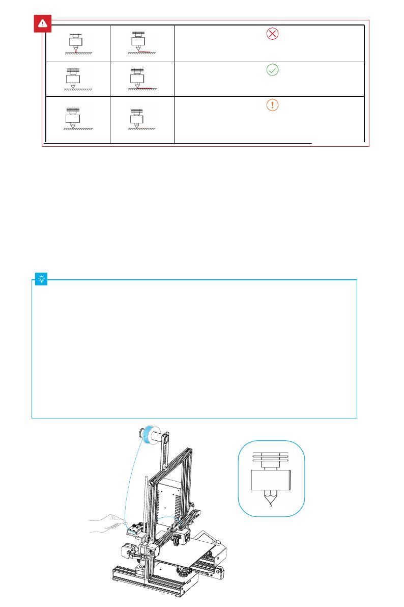
The nozzle is too far away from the platform,
and the filaments cannot stick to the platform.
The nozzle is too close to the platform, and
the filament is not extruded enough, which
may damage the platform.
The filament is evenly extruded and sticks to
the platform just right.
A.In order to successfully load the lament, please trim the end of the lament at an
angle of 45 degrees.
B.Press the lament until it passes through the lament detection hole. Then press
and hold the extruder handle to insert the lament into Teon tube until it reaches
the nozzle.
C.Warm up the nozzle. If the lament ows out of the nozzle when the temperature
reaches the target value, the lament is properly loaded.
Loading the Filament
Replacing the lament:
1.When the printer is not printing:
A. Heat the nozzle to 185 or higher, wait for the lament in the nozzle to soften. Then
press and hold the extrusion handle to quickly extract the lament to prevent it from
clogging in the heat break.
B. Pause the printing. After the printer stops, press and hold the extrusion handle and
quickly extract the lament to prevent it from clogging in the heat break.
C. Place the new lament onto the rack and press it through the lament detector.
Press and hold the extrusion handle to insert the lament into the nozzle. Then push the
lament to squeeze out the residual lament in the nozzle and clean up the nozzle
before resuming printing.
Model Slicing Tutorial
1. Scan the QR code above to download
from the website, or find the Creality
software on your memory card and install it.
Creality
Slicer 4.8.2
2.Go to Preferences → Configure Creality → Select language
→ Next → Finish to complete the configuration.
3.Select the model of this printer (Ender-3 E) 4.Enter parameters → Close.
5.Launch the
Creality slicing software.
6.Load the file.
7.Select the file.
Creality
Slicer 4.8.2
Load
The file name must only contain Latin
letters and digits.
Chinese characters or special symbols
must not be used.
Do not insert any levelling codes, otherwise conflicts may
be caused!
Note: For details on using the software please refer to the
slicing software user manual on the memory card.
Slicing tips: Click the Random Information folder → Slicing
software instructions.
8.Generate the G-code file → Save it to the memory card. 9.Insert the memory card → Print → Select
from the menu → Select the file used for printing.
E
E
E
250
E
Start Printing
Before printing, please check the printer again following these steps:
When the printer is powered off:
1.The nozzle is tightly connected and moves smoothly to the left and right.
2.The X axis is horizontal and stable (not wobbling up or down), and it
moves run smoothly up and down. 3.The Y axis is tightly connected. The
platform does not shake and moves back and forth smoothly. 4.The
lament rack does not shake. The rollers are smooth. The lament
extrusion is smooth.
When the printer is powered on: Please make sure to select the correct
voltage mode
1.The screen display and knob work properly. The movements of the X, Y,
and Z axes are smooth.
2.The nozzle and hotbed heat up properly.
3.The feed and return of the lament works properly.
About the Printer
1Material Barrel
2Z-axis left profile
3Printhead kit
4Rack
5
USB Port
6
TF Card Port
720 Profile end cap
8 Z-axis right profile
9 Power supply module
10 Z-axis passive component
11 X adjusting component
12 Display Screen
13 Voltage switch
14 Base component
15 Top gantry profile
16 Screw rod
18 Extrusion kit
19 Z-Axis Motor
17 X-axis profile
8
11
4
1
2
3
5
6
7
9
10
12 19
17
16
15
18
14
13
Add: 18F, JinXiuHongDu Building, Meilong Blvd., Longhua Dist., Shenzhen, China
For the after-sales service and technical support, please scan the QR code on the left.
SHENZHEN CREALITY 3D TECHNOLOGY CO., LTD.
Due to the differences between different machine models, the physical objects and the final images can differ.
The final explanation rights shall be reserved by Shenzhen Creality 3D Technology CO., Ltd.
11 Device Specifications
Model Ender-3 E
1
0.1mm-0.4mm
0.4mm (standard)
±0.1mm
3D Creator Slicer, Repetier-Host, Cura, Simplify3D
Input: 100-120V, 200-240V~ 50/60Hz; Output: DC 24V
≤100°C
Layer Height
Nozzle Diameter
Accuracy
Printing Material
Supported Formats
Printing Method
FDMModeling Technology
Number of Nozzles
Supported Slicing Software
Power Specifications
Total Power
Hotbed Temperature
≤250°C
Yes
Nozzle Temperature
Resume Printing Function
YesFilament Detection
Yes
CR touch
English
Language
Windows XP/7/10/MAC/LinuxPC Operating Systems
Printing Speed
220*220*250mm
Modeling Dimensions
General Specifications
1.75mm PLA
STL/OBJ/AMF
≤ 80mm/s, recommended between 30 to 60mm/s
270W
Memory card offline printing or online printing
  • Page 1 1
  • Page 2 2
  • Page 3 3
  • Page 4 4
  • Page 5 5
  • Page 6 6
  • Page 7 7
  • Page 8 8
  • Page 9 9
  • Page 10 10
  • Page 11 11
  • Page 12 12
  • Page 13 13
  • Page 14 14
  • Page 15 15
  • Page 16 16

Ender 3 E 3D Printer User manual

Category
3D printers
Type
User manual
This manual is also suitable for

Ender 3 E 3D Printer: Experience limitless creativity with precise FDM modeling capabilities, crafting objects up to 220 x 220 x 250mm. Achieve intricate details with 0.1mm layer height resolution and 0.4mm nozzle diameter. Explore a wide range of compatible filaments, including PLA, to bring your designs to life.

Ask a question and I''ll find the answer in the document

Finding information in a document is now easier with AI