Page is loading ...

BEFORE INSTALLING:
All installations should comply with National and local Electrical codes.
If you have any doubts concerning installation contact a qualied licensed
electrician.
CAUTION:
To reduce the risk of re, do not install closer than 1 inch to cabinet wall or in
compartment smaller than 12 inches by 12 inches by 12 inches.
IMPORTANT SAFETY INSTRUCTIONS
a) Read all instructions.
b) Do not conceal or extend exposed conductors through a building wall,
oor or ceiling.
c) Install this system in dry or damp locations only.
d) To reduce risk of re and burns, do not install this lighting system where
the exposed bare conductors can be shorted or contact any conductive
materials.
e) To reduce the risk of re and overheating, make sure all connections
are tight.
f) Do not install any luminaire closer than 6 inches (15.25cm) from any
curtain, or similar combustible materials.
g) Power supply has three distinct sections:
o line voltage (AC Input), black and white
o 0-10V dimmer (DC input), purple and grey
o low voltage (DC Output), red and blue
It is important to keep the line voltage and the DC voltage
wires separate.
h) Turn o electrical power before modifying the lighting system in any way.
We’re here to help 866-558-5706
Hrs: M-F 9am to 5pm EST
Kichler 8TD24V090BKT, 8TD24V060BKT Power Supplies
Installation Instructions
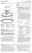
MOUNTING SCREW
IS-8TD24V09-US
NOTE: Kichler 8TD-Series (24V) are not compatible with dimmers
when used in conjunction with tape light controllers, also not
compatible with the phase cut dimmers.
Kichler 8TD-Series (24V) are only compatible with 0-10V dimmers.
THIS DEVICE COMPLIES WITH PART 15 OF THE FCC RULES. OPERATION IS SUBJECT TO THE FOLLOWING TWO CONDITIONS: (1) THIS DEVICE MAY NOT CAUSE HARMFUL
INTERFERENCE, AND (2) THIS DEVICE MUST ACCEPT ANY INTERFERENCE RECEIVED, INCLUDING INTERFERENCE THAT MAY CAUSE UNDESIRED OPERATION.
SAVE THESE INSTRUCTIONS
1) Turn o power.
2) Determine desired location for mounting power supply. Power supply should
be located within 25’ of rst luminaire.
3) Secure power supply using provided mounting screws. Secure into wall studs
if possible, otherwise, use appropriate anchors rated for proper wall material
and hanging weight (not included).
4) Using the pre-punched knock-outs in the metal enclosure, route the
120V - 277V line voltage to the primary side (AC Input) of the power supply.
NOTE: A proper UL listed cable connector must be used in the knock-out to
provide strain relief and wire protection (cable connector provided).
5) Make grounding connection (connector provided).
6) Make wire connections (connectors are provided). Reference chart below for
connections and wire accordingly.
Connect Line (Black or Red
Supply Wire) to:
Connect Neutral (White
Supply Wire) to:
Black White
*Parallel cord (round &
smooth)
*Parallel cord (square &
ridged)
Clear without tracer Clear with white tracer
*Note: When parallel wire (SPT 1 &
SPT 2) are used. The neutral wire
is square shaped or ridged and the
other wire will be round in shape or
smooth (See illus.)
Neutral Wire
7) Total load of the installed lighting system must not exceed rated Wattage of
power supply.
NOTE: After determining the layout of the system, add the
wattage of each luminaire/xture together to calculate the total system
consumption. The calculated total system consumption should be equal
or less than the Class 2 power supply rating that is being used.
8) Using the pre-punched knock-outs in the metal enclosure, route and connect
the leads from 0-10V dimmer to the secondary side 0-10V dimmer (DC input)
of the power supply.
NOTE: Connect dimmer+ to the purple wire and dimmer- to the grey wire
using the supplied wire nuts or other UL approved connectors.
9) Using the pre-punched knock-outs in the metal enclosure, route and connect
the lighting system leads to the secondary side 0-10V dimmer (DC input) of
the power supply.
NOTE: Connect positive to the red wire and negative to the blue wire
using the supplied wire nuts or other UL approved connectors. Do not
exceed manufacturers’ wiring combination specications for size and quantity
of conductors.
NOTE: A proper UL listed cable connector must be used in the knock-outs to
provide wire protection (cable connector provided).
PRIMARY SIDE CABLE
CONNECTOR
SECONDARY SIDE CABLE
CONNECTOR
PRIMARY SIDE WIRE
COMPARTMENT
SECONDARY SIDE WIRE
COMPARTMENT
FIXTURE DIAGRAM

BEFORE INSTALLING:
All installations should comply with National and local Electrical codes.
If you have any doubts concerning installation contact a qualied licensed
electrician.
CAUTION:
To reduce the risk of re, do not install closer than 1 inch to cabinet wall or in
compartment smaller than 12 inches by 12 inches by 12 inches.
IMPORTANT SAFETY INSTRUCTIONS
a) Read all instructions.
b) Do not conceal or extend exposed conductors through a building wall,
oor or ceiling.
c) Install this system in dry or damp locations only.
d) To reduce risk of re and burns, do not install this lighting system where
the exposed bare conductors can be shorted or contact any conductive
materials.
e) To reduce the risk of re and overheating, make sure all connections
are tight.
f) Do not install any luminaire closer than 6 inches (15.25cm) from any
curtain, or similar combustible materials.
g) Power supply has three distinct sections:
o line voltage (AC Input), black and white
o 0-10V dimmer (DC input), purple and grey
o low voltage (DC Output), red and blue
It is important to keep the line voltage and the DC voltage
wires separate.
h) Turn o electrical power before modifying the lighting system in any way.
We’re here to help 866-558-5706
Hrs: M-F 9am to 5pm EST
Kichler 8TD24V090BKT, 8TD24V060BKT Power Supplies
Installation Instructions
MOUNTING SCREW
IS-8TD24V09-CB
NOTE: Kichler 8TD-Series (24V) are not compatible with dimmers
when used in conjunction with tape light controllers, also not
compatible with the phase cut dimmers.
Kichler 8TD-Series (24V) are only compatible with 0-10V dimmers.
THIS DEVICE COMPLIES WITH PART 15 OF THE FCC RULES. OPERATION IS SUBJECT TO THE FOLLOWING TWO CONDITIONS: (1) THIS DEVICE MAY NOT CAUSE HARMFUL
INTERFERENCE, AND (2) THIS DEVICE MUST ACCEPT ANY INTERFERENCE RECEIVED, INCLUDING INTERFERENCE THAT MAY CAUSE UNDESIRED OPERATION.
SAVE THESE INSTRUCTIONS
1) Turn o power.
2) Determine desired location for mounting power supply. Power supply should
be located within 25’ of rst luminaire.
3) Secure power supply using provided mounting screws. Secure into wall studs
if possible, otherwise, use appropriate anchors rated for proper wall material
and hanging weight (not included).
4) Using the pre-punched knock-outs in the metal enclosure, route the
120V - 277V line voltage to the primary side (AC Input) of the power supply.
NOTE: A proper UL listed cable connector must be used in the knock-out to
provide strain relief and wire protection (cable connector provided).
5) Make grounding connection (connector provided).
6) Make wire connections (connectors are provided). Reference chart below for
connections and wire accordingly.
Connect Line (Black or Red
Supply Wire) to:
Connect Neutral (White
Supply Wire) to:
Black White
*Parallel cord (round &
smooth)
*Parallel cord (square &
ridged)
Clear without tracer Clear with white tracer
*Note: When parallel wire (SPT 1 &
SPT 2) are used. The neutral wire
is square shaped or ridged and the
other wire will be round in shape or
smooth (See illus.)
Neutral Wire
7) Total load of the installed lighting system must not exceed rated Wattage of
power supply.
NOTE: After determining the layout of the system, add the
wattage of each luminaire/xture together to calculate the total system
consumption. The calculated total system consumption should be equal
or less than the Class 2 power supply rating that is being used.
8) Using the pre-punched knock-outs in the metal enclosure, route and connect
the leads from 0-10V dimmer to the secondary side 0-10V dimmer (DC input)
of the power supply.
NOTE: Connect dimmer+ to the purple wire and dimmer- to the grey wire
using the supplied wire nuts or other UL approved connectors.
9) Using the pre-punched knock-outs in the metal enclosure, route and connect
the lighting system leads to the secondary side 0-10V dimmer (DC input) of
the power supply.
NOTE: Connect positive to the red wire and negative to the blue wire
using the supplied wire nuts or other UL approved connectors. Do not
exceed manufacturers’ wiring combination specications for size and quantity
of conductors.
NOTE: A proper UL listed cable connector must be used in the knock-outs to
provide wire protection (cable connector provided).
PRIMARY SIDE CABLE
CONNECTOR
SECONDARY SIDE CABLE
CONNECTOR
PRIMARY SIDE WIRE
COMPARTMENT
SECONDARY SIDE WIRE
COMPARTMENT
FIXTURE DIAGRAM
I NSTRUCTIONS
For
Assembling and Installing Fixtures in Canada
Pour L’assemblage et L’installation Au Canada
/